- Cisco Unified Communications Manager and Cisco IOS Interoperability Features Roadmap
- Overview of Cisco Unified Communications Manager and Cisco IOS Interoperability
- Configuring MGCP Gateway Support for Cisco Unified Communications Manager
- Configuring Enhanced Conferencing and Transcoding for Voice Gateway Routers
- Configuring MGCP PRI Backhaul and T1 CAS Support for Cisco Unified Communications Manager
- Configuring MGCP-Controlled Backhaul of BRI Signaling in Conjunction with Cisco Unified Communications Manager
- Configuring Tone Download to MGCP Gateways
- Configuring MCID for Cisco IOS Voice Gateways
- Configuring RSVP Agent
This documentation has moved
Bias-Free Language
The documentation set for this product strives to use bias-free language. For the purposes of this documentation set, bias-free is defined as language that does not imply discrimination based on age, disability, gender, racial identity, ethnic identity, sexual orientation, socioeconomic status, and intersectionality. Exceptions may be present in the documentation due to language that is hardcoded in the user interfaces of the product software, language used based on RFP documentation, or language that is used by a referenced third-party product. Learn more about how Cisco is using Inclusive Language.
- Updated:
- June 13, 2008
Chapter: Configuring MGCP-Controlled Backhaul of BRI Signaling in Conjunction with Cisco Unified Communications Manager
- Contents
- Prerequisites for MGCP-Controlled Backhaul of BRI Signaling
- Restrictions for MGCP-Controlled Backhaul of BRI Signaling
- Information About MGCP-Controlled Backhaul of BRI Signaling
- How to Configure MGCP-Controlled Backhaul of BRI Signaling
Configuring MGCP-Controlled Backhaul of BRI Signaling in Conjunction with Cisco Unified Communications Manager
The MGCP-Controlled Backhaul of Basic Rate Interface (BRI) Signaling in Conjunction with Cisco Unified Communications Manager feature provides MGCP service to remote-office gateways that connect by means of ISDN BRI trunks to a centralized Cisco Unified Communications Manager.
Feature benefits include the following:
•![]() Centralized call-management architecture, enabling a high degree of network control
Centralized call-management architecture, enabling a high degree of network control
•![]() Short voice cut-through times
Short voice cut-through times
•![]() Graceful evolution to new technology and to AVVID
Graceful evolution to new technology and to AVVID
Only the ETSI BRI basic-net3 switch type is supported.
Feature History for MGCP-Controlled Backhaul of BRI Signaling in Conjunction with Cisco Unified Communications Manager
Finding Support Information for Platforms and Cisco IOS Software Images
Use Cisco Feature Navigator to find information about platform support and Cisco IOS software image support. Access Cisco Feature Navigator at http://www.cisco.com/go/fn. You must have an account on Cisco.com. If you do not have an account or have forgotten your username or password, click Cancel at the login dialog box and follow the instructions that appear.

Note ![]() For more information about this and related Cisco IOS voice features, see the following:
For more information about this and related Cisco IOS voice features, see the following:
•![]() "Overview of Cisco Unified Communications Manager and Cisco IOS Interoperability" on page 13.
"Overview of Cisco Unified Communications Manager and Cisco IOS Interoperability" on page 13.
•![]() Entire Cisco IOS Voice Configuration Library—including library preface and glossary, other feature documents, and troubleshooting documentation—at http://www.cisco.com/univercd/cc/td/doc/product/software/ios123/123cgcr/voice_c/vcl.htm.
Entire Cisco IOS Voice Configuration Library—including library preface and glossary, other feature documents, and troubleshooting documentation—at http://www.cisco.com/univercd/cc/td/doc/product/software/ios123/123cgcr/voice_c/vcl.htm.
Contents
•![]() Prerequisites for MGCP-Controlled Backhaul of BRI Signaling
Prerequisites for MGCP-Controlled Backhaul of BRI Signaling
•![]() Restrictions for MGCP-Controlled Backhaul of BRI Signaling
Restrictions for MGCP-Controlled Backhaul of BRI Signaling
•![]() Information About MGCP-Controlled Backhaul of BRI Signaling
Information About MGCP-Controlled Backhaul of BRI Signaling
•![]() How to Configure MGCP-Controlled Backhaul of BRI Signaling
How to Configure MGCP-Controlled Backhaul of BRI Signaling
•![]() Configuration Examples for MGCP-Controlled Backhaul of BRI Signaling
Configuration Examples for MGCP-Controlled Backhaul of BRI Signaling
Prerequisites for MGCP-Controlled Backhaul of BRI Signaling
Cisco Unified Communications Manager
•![]() Cisco Unified Communications Manager 4.1(1) or a later release
Cisco Unified Communications Manager 4.1(1) or a later release
Cisco Voice Gateway
•![]() 20-MB flash memory
20-MB flash memory
•![]() 64-MB DRAM
64-MB DRAM
•![]() One of the supported combinations of BRI voice interface card (VIC) and network module:
One of the supported combinations of BRI voice interface card (VIC) and network module:
–![]() VIC-2BRI-NT/TE or VIC-2BRI-S/T in NM-1V or NM-2V with Cisco IOS Release 12.3(11)T or a later release
VIC-2BRI-NT/TE or VIC-2BRI-S/T in NM-1V or NM-2V with Cisco IOS Release 12.3(11)T or a later release
–![]() VIC2-2BRI-NT/TE in NM-HD-1V, NM-HD-2V, NM-HD-2VE, or NM-HDV2 with Cisco IOS Release 12.4(2)T or a later release
VIC2-2BRI-NT/TE in NM-HD-1V, NM-HD-2V, NM-HD-2VE, or NM-HDV2 with Cisco IOS Release 12.4(2)T or a later release
–![]() EM-4BRI-NT/TE in EVM-HD-8FXS/DID with Cisco IOS Release 12.4(2)T or a later release
EM-4BRI-NT/TE in EVM-HD-8FXS/DID with Cisco IOS Release 12.4(2)T or a later release
•![]() MGCP enabled globally in a VoIP network
MGCP enabled globally in a VoIP network
•![]() MGCP control of dial peers and voice ports
MGCP control of dial peers and voice ports
•![]() MGCP single-point configuration enabled
MGCP single-point configuration enabled
Note ![]() For MGCP configuration instructions, see "Configuring MGCP Gateway Support for Cisco Unified Communications Manager" on page 23.
For MGCP configuration instructions, see "Configuring MGCP Gateway Support for Cisco Unified Communications Manager" on page 23.
Restrictions for MGCP-Controlled Backhaul of BRI Signaling
•![]() BRI backhaul uses the enhanced interface numbering support available in Cisco IOS Release 12.3(11)T and later. Previous releases supported only the slot/subslot/port format with the subslot forced to 0 on the Cisco 2600 series, Cisco 3600 series, and Cisco 3700 series. Cisco IOS Release 12.3(11)T and later releases support both the slot/port and slot/subslot/port interface numbering formats for BRI backhaul.
BRI backhaul uses the enhanced interface numbering support available in Cisco IOS Release 12.3(11)T and later. Previous releases supported only the slot/subslot/port format with the subslot forced to 0 on the Cisco 2600 series, Cisco 3600 series, and Cisco 3700 series. Cisco IOS Release 12.3(11)T and later releases support both the slot/port and slot/subslot/port interface numbering formats for BRI backhaul.
•![]() Only the ETSI BRI Basic-NET3 switch type is supported.
Only the ETSI BRI Basic-NET3 switch type is supported.
•![]() BRI calls are cleared during MGCP gateway fallback and rehome because ISDN BRI L2 must be reinitiated and brought up again by the new L3 task.
BRI calls are cleared during MGCP gateway fallback and rehome because ISDN BRI L2 must be reinitiated and brought up again by the new L3 task.
•![]() Do not add the application mgcpapp command to voice dial peers that support BRI backhaul.
Do not add the application mgcpapp command to voice dial peers that support BRI backhaul.
Information About MGCP-Controlled Backhaul of BRI Signaling
To configure MGCP-controlled backhaul of BRI signaling, you should understand the following concept:
•![]() MGCP-Controlled Backhaul of BRI Signaling
MGCP-Controlled Backhaul of BRI Signaling
MGCP-Controlled Backhaul of BRI Signaling
The MGCP-Controlled Backhaul of BRI Signaling feature supports a centralized Cisco Unified Communications Manager architecture with BRI trunks connected to remote branch offices. Transporting signaling information from a branch-office MGCP gateway to a centralized media-gateway controller for processing is called backhaul. D-channel signal information is backhauled to Cisco Unified Communications Manager through a TCP session. All Q.931 messages are passed through the TCP connection between the Cisco MGCP gateway and Cisco Unified Communications Manager. The MGCP gateway neither parses nor has any knowledge of the contents of those messages.
This feature enables you to connect remote ISDN PBXs and key systems to a Cisco ISDN BRI network termination (network side) or PSTN Class 4/5 switch through a Cisco ISDN BRI terminal equipment (as user side) interface. External call-control entities, such as one or more Cisco Unified Communications Manager servers, provide voice service between local and remote branch offices.
Figure 9 depicts a typical network-side scenario. NT denotes network termination; TE denotes terminal equipment.
Figure 9 Typical ISDN BRI Network-Side Scenario
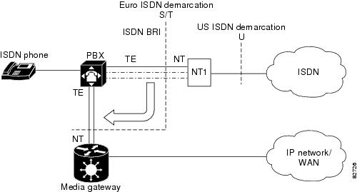
Figure 10 shows a typical user-side scenario.
Figure 10 ISDN BRI User-Side Scenario
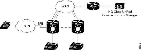
The following is the sequence of events during normal backhaul:
1. ![]() A call comes in from the PSTN and passes over the BRI trunk to the MGCP gateway.
A call comes in from the PSTN and passes over the BRI trunk to the MGCP gateway.
2. ![]() The MGCP gateway passes signaling information from the call across the WAN to the Cisco Unified Communications Manager at headquarters.
The MGCP gateway passes signaling information from the call across the WAN to the Cisco Unified Communications Manager at headquarters.
3. ![]() The Cisco Unified Communications Manager instructs the MGCP gateway on how to set up and manage the call.
The Cisco Unified Communications Manager instructs the MGCP gateway on how to set up and manage the call.
4. ![]() The call is established.
The call is established.
How to Configure MGCP-Controlled Backhaul of BRI Signaling
This section contains the following procedures:
•![]() Configuring the BRI Interface as an MGCP-BRI Backhaul Endpoint (required)
Configuring the BRI Interface as an MGCP-BRI Backhaul Endpoint (required)
•![]() Verifying MGCP-BRI Backhaul Configuration (optional)
Verifying MGCP-BRI Backhaul Configuration (optional)
•![]() Troubleshooting Tips for MGCP-Controlled Backhaul of BRI Signaling (optional)
Troubleshooting Tips for MGCP-Controlled Backhaul of BRI Signaling (optional)
Configuring the BRI Interface as an MGCP-BRI Backhaul Endpoint
SUMMARY STEPS
1. ![]() enable
enable
2. ![]() configure terminal
configure terminal
3. ![]() interface bri slot/port
interface bri slot/port
4. ![]() shutdown
shutdown
5. ![]() isdn switch-type basic-net3
isdn switch-type basic-net3
6. ![]() isdn bind-L3 ccm-manager service mgcp
isdn bind-L3 ccm-manager service mgcp
7. ![]() no shutdown
no shutdown
8. ![]() no mgcp
no mgcp
9. ![]() mgcp
mgcp
10. ![]() exit
exit
DETAILED STEPS
Verifying MGCP-BRI Backhaul Configuration
SUMMARY STEPS
1. ![]() show isdn status
show isdn status
2. ![]() show ccm-manager
show ccm-manager
3. ![]() show ccm-manager backhaul
show ccm-manager backhaul
4. ![]() show mgcp endpoint
show mgcp endpoint
DETAILED STEPS
Step 1 ![]() show isdn status
show isdn status
Use the show isdn status command to verify that Layer 2 is established and that Layer 3 is configured as Cisco Unified Communications Manager. This output displays only if TEI negotiation is performed at startup.
Router# show isdn status
ISDN BRI1/1 interface
dsl 1, interface ISDN Switchtype = basic-net3
L2 Protocol = Q.921 L3 Protocol(s) = CCM-MANAGER
Layer 1 Status:
ACTIVE
Layer 2 Status:
TEI = 64, Ces = 1, SAPI = 0, State = MULTIPLE_FRAME_ESTABLISHED
Note ![]() Use this command only if TEI negotiation is done at startup. Otherwise, TEI negotiation is done when the first call is placed, so output shows Layer 2 with no TEI negotiated and Layer 3 as down.
Use this command only if TEI negotiation is done at startup. Otherwise, TEI negotiation is done when the first call is placed, so output shows Layer 2 with no TEI negotiated and Layer 3 as down.
Step 2 ![]() show ccm-manager
show ccm-manager
Use the show ccm-manager command to verify your Cisco Unified Communications Manager configuration on the gateway.
Router# show ccm-manager
MGCP Domain Name:3845-1.cisco.com
Priority Status Host
============================================================
Primary Registered 10.3.102.99
First Backup None
Second Backup None
Current active Call Manager: 10.3.102.99
Backhaul/Redundant link port: 2428
Failover Interval: 30 seconds
Keepalive Interval: 15 seconds
Last keepalive sent: 20:58:35 UTC Sep 3 2004 (elapsed time:00:00:11)
Last MGCP traffic time: 20:58:35 UTC Sep 3 2004 (elapsed time:00:00:11)
Last failover time: None
Last switchback time: None
Switchback mode: Graceful
MGCP Fallback mode: Not Selected
Last MGCP Fallback start time: None
Last MGCP Fallback end time: None
MGCP Download Tones: Disabled
Configuration Error History:
FAX mode:cisco
Step 3 ![]() show ccm-manager backhaul
show ccm-manager backhaul
Use the show ccm-manager backhaul command to display information about the BRI backhaul link.
Router# show ccm-manager backhaul
Backhaul Link info:
Link Protocol: TCP
Remote Port Number:2428
Remote IP Address: 10.3.102.99
Current Link State:OPEN
Statistics:
Packets recvd: 4
Recv failures: 0
Packets xmitted:2
Xmit failures: 0
BRI Ports being backhauled:
Slot 0, VIC 0, port 0
Slot 1, VIC 0, port 0
Step 4 ![]() show mgcp endpoint
show mgcp endpoint
Use the show mgcp endpoint command to display a list of your MGCP endpoints.
Router# show mgcp endpoint
BRI/S1/SU0/P1/1@3745-1
BRI/S1/SU0/P1/2@3745-1
Troubleshooting Tips for MGCP-Controlled Backhaul of BRI Signaling
Table 10 lists commands that are available for troubleshooting your configuration.
Configuring SRTP Mode on Cisco IOS MGCP Gateways
SRTP mode provides secure VoIP calls by addressing security requirements for privacy, integrity, and confidentiality of voice conversations. IPsec, a standards-based set of security protocols and algorithms, ensures that signaling information that is sent between the gateway and Cisco Unified Communications Manager are encrypted. Media encryption using standards-based Secure Real-Time Transport Protocol (SRTP) ensures that media streams between supported devices are secure.
Perform this task to configure SRTP mode on the gateway.
Prerequisites for SRTP Mode
You should first establish an IPsec connection between Cisco Unified Communications Manager and the MGCP gateway before using the MGCP SRTP package. Otherwise, media keys are sent in clear text and your voice call is not considered secure.
SUMMARY STEPS
1. ![]() enable
enable
2. ![]() configure terminal
configure terminal
3. ![]() mgcp package-capability srtp-package
mgcp package-capability srtp-package
4. ![]() mgcp validate call-agent source-ipaddr
mgcp validate call-agent source-ipaddr
5. ![]() exit
exit
DETAILED STEPS
Configuration Examples for MGCP-Controlled Backhaul of BRI Signaling
This section provides the following configuration example:
•![]() MGCP BRI Backhaul on Cisco 3745: Example
MGCP BRI Backhaul on Cisco 3745: Example
•![]() MGCP BRI Backhaul on Cisco 3640: Example
MGCP BRI Backhaul on Cisco 3640: Example
MGCP BRI Backhaul on Cisco 3745: Example
Router# show running-config
Building configuration...
Current configuration :3913 bytes
!
version 12.3
service timestamps debug datetime msec
service timestamps log datetime msec
no service password-encryption
!
hostname Router
!
boot-start-marker
boot-end-marker
!
!
no network-clock-participate slot 1
no network-clock-participate slot 2
no network-clock-participate slot 3
no network-clock-participate slot 4
no network-clock-participate wic 0
no network-clock-participate wic 1
no network-clock-participate wic 2
no network-clock-participate aim 0
no network-clock-participate aim 1
no aaa new-model
ip subnet-zero
ip cef
!
!
!
ip dhcp pool phone1
host 10.3.102.102 255.255.0.0
client-identifier 0100.1121.116b.dd
option 150 ip 10.3.102.99
default-router 10.3.102.2
!
!
ip domain name cisco.com
ip ids po max-events 100
no ftp-server write-enable
isdn switch-type basic-net3
voice-card 1
no dspfarm
!
voice-card 2
no dspfarm
!
voice-card 3
no dspfarm
!
!
!
ccm-manager switchback immediate
ccm-manager fallback-mgcp
ccm-manager redundant-host 10.3.102.98
ccm-manager mgcp
!
!
!
interface FastEthernet0/0
ip address 10.3.102.2 255.255.0.0
duplex auto
speed auto
!
interface FastEthernet0/1
no ip address
shutdown
duplex auto
speed auto
!
interface BRI1/0
no ip address
isdn switch-type basic-net3
isdn incoming-voice voice
isdn bind-l3 ccm-manager service mgcp
isdn skipsend-idverify
!
interface BRI1/1
no ip address
isdn switch-type basic-net3
isdn protocol-emulate network
isdn layer1-emulate network
isdn incoming-voice voice
isdn skipsend-idverify
!
interface BRI2/0
no ip address
isdn switch-type basic-net3
isdn incoming-voice voice
isdn bind-l3 ccm-manager service mgcp
isdn skipsend-idverify
!
interface BRI2/1
no ip address
isdn switch-type basic-net3
isdn protocol-emulate network
isdn layer1-emulate network
isdn incoming-voice voice
isdn skipsend-idverify
!
interface BRI3/0
no ip address
isdn switch-type basic-net3
isdn incoming-voice voice
isdn bind-l3 ccm-manager service mgcp
isdn skipsend-idverify
!
interface BRI3/1
no ip address
isdn switch-type basic-net3
isdn protocol-emulate network
isdn layer1-emulate network
isdn incoming-voice voice
isdn skipsend-idverify
!
!
ip default-gateway 10.3.0.1
ip classless
ip route 0.0.0.0 0.0.0.0 10.3.0.1
!
ip http server
no ip http secure-server
!
!
access-list 10 deny 10.3.102.99 log
access-list 10 permit any
!
!
!
control-plane
!
!
call application alternate DEFAULT
!
!
voice-port 1/1/0
!
voice-port 1/1/1
!
voice-port 2/0/0
!
voice-port 2/0/1
!
voice-port 3/0/0
!
voice-port 3/0/1
!
voice-port 3/1/0
!
voice-port 3/1/1
!
voice-port 3/1/2
!
voice-port 3/1/3
!
!
mgcp
mgcp call-agent 10.3.102.99 service-type mgcp version 0.1
mgcp package-capability srtp-package
!
mgcp profile default
!
!
!
dial-peer voice 1 pots
application mgcpapp
direct-inward-dial
port 3/0/0
forward-digits all
!
dial-peer voice 100 voip
application mgcpapp
destination-pattern 9...
session target ipv4:10.3.102.1
incoming called-number .
!
dial-peer voice 2 pots
destination-pattern 5001
port 3/1/0
!
dial-peer voice 4 pots
destination-pattern 6T
direct-inward-dial
port 3/0/1
!
dial-peer voice 3 pots
destination-pattern 5002
port 3/1/3
!
dial-peer voice 11 pots
destination-pattern 2T
direct-inward-dial
port 2/0/1
!
dial-peer voice 12 pots
application mgcpapp
direct-inward-dial
port 2/0/0
forward-digits all
!
!
!
call-manager-fallback
max-conferences 8
ip source-address 10.3.102.2 port 2000
max-ephones 2
max-dn 4
!
!
line con 0
exec-timeout 0 0
line aux 0
line vty 0 4
login
!
end
MGCP BRI Backhaul on Cisco 3640: Example
version 12.2
service timestamps debug uptime
service timestamps log uptime
no service password-encryption
no service dhcp
!
hostname 3640
!
!
voice-card 3
!
ip subnet-zero
!
!
ip domain name cisco.com
!
isdn switch-type primary-qsig
!
!
voice call carrier capacity active
!
voice service voip
h323
call start slow
!
!
!
!
mta receive maximum-recipients 0
ccm-manager mgcp
!
controller T1 3/0
framing esf
clock source internal
linecode b8zs
pri-group timeslots 1-24 service mgcp
!
controller T1 3/1
framing esf
linecode b8zs
!
!
!
interface FastEthernet0/0
ip address 10.15.43.101 255.255.0.0
duplex auto
speed auto
no cdp enable
!
interface Serial0/0
no ip address
encapsulation frame-relay
shutdown
clockrate 125000
frame-relay lmi-type ansi
!
interface FastEthernet0/1
no ip address
shutdown
duplex auto
speed auto
!
interface Serial0/1
no ip address
shutdown
clockrate 125000
!
interface BRI1/0
no ip address
isdn switch-type basic-net3
isdn incoming-voice voice
isdn bind-l3 ccm-manager service mgcp
!
interface BRI1/1
no ip address
isdn switch-type basic-qsig
!
interface Serial3/0:23
no ip address
no logging event link-status
isdn switch-type primary-qsig
isdn incoming-voice voice
no cdp enable
!
ip default-gateway 10.15.10.11
ip classless
ip route 0.0.0.0 0.0.0.0 10.15.10.11
ip http server
!
ip pim bidir-enable
!
!
!
call rsvp-sync
!
voice-port 1/0/0
!
voice-port 1/0/1
!
voice-port 2/0/0
!
voice-port 2/0/1
!
voice-port 2/1/0
!
voice-port 2/1/1
!
voice-port 3/0:23
!
mgcp
mgcp call-agent 10.14.181.10 service-type mgcp version 0.1
mgcp sdp simple
!
mgcp profile default
!
!
!
dial-peer cor custom
!
!
!
dial-peer voice 6000 pots
application mgcpapp
port 2/0/0
!
dial-peer voice 4000 pots
application mgcpapp
port 2/0/1
!
!
line con 0
exec-timeout 0 0
line aux 0
line vty 0 4
login
!
!
end
Where to Go Next
•![]() To configure conferencing, transcoding, and MTP support on a Cisco IOS gateway, see "Configuring Enhanced Conferencing and Transcoding for Voice Gateway Routers" on page 67.
To configure conferencing, transcoding, and MTP support on a Cisco IOS gateway, see "Configuring Enhanced Conferencing and Transcoding for Voice Gateway Routers" on page 67.
•![]() To enable MGCP PRI backhaul support, see "Configuring MGCP PRI Backhaul and T1 CAS Support for Cisco Unified Communications Manager" on page 113.
To enable MGCP PRI backhaul support, see "Configuring MGCP PRI Backhaul and T1 CAS Support for Cisco Unified Communications Manager" on page 113.
•![]() To download region-specific tones and their associated frequencies, amplitudes, and cadences, see "Configuring Tone Download to MGCP Gateways" on page 145.
To download region-specific tones and their associated frequencies, amplitudes, and cadences, see "Configuring Tone Download to MGCP Gateways" on page 145.
Additional References
•![]() "Cisco Unified Communications Manager and Cisco IOS Interoperability Features Roadmap" on page 9—Describes how to access Cisco Feature Navigator; also lists and describes, by Cisco IOS release, Cisco Unified Communications Manager and Cisco IOS interoperability features.
"Cisco Unified Communications Manager and Cisco IOS Interoperability Features Roadmap" on page 9—Describes how to access Cisco Feature Navigator; also lists and describes, by Cisco IOS release, Cisco Unified Communications Manager and Cisco IOS interoperability features.
•![]() "Overview of Cisco Unified Communications Manager and Cisco IOS Interoperability" on page 13—Describes basics of underlying technology and lists related documents.
"Overview of Cisco Unified Communications Manager and Cisco IOS Interoperability" on page 13—Describes basics of underlying technology and lists related documents.
•![]() "Configuring ISDN BRI" in the Cisco IOS Dial Technologies Configuration Guide, Release 12.4—Describes how to configure ISDN BRI on the voice gateway.
"Configuring ISDN BRI" in the Cisco IOS Dial Technologies Configuration Guide, Release 12.4—Describes how to configure ISDN BRI on the voice gateway.
•![]() "ISDN Switch Types, Codes, and Values" appendix in the Debug Command Reference, Release 12.4—Describes supported switch types.
"ISDN Switch Types, Codes, and Values" appendix in the Debug Command Reference, Release 12.4—Describes supported switch types.
•![]() Cisco Unified Communications Manager documentation—Describes how to install and configure Cisco Unified Communications Manager.
Cisco Unified Communications Manager documentation—Describes how to install and configure Cisco Unified Communications Manager.
 Feedback