- Overview: Secure Connectivity
-
- Implementing and Managing PKI Features Roadmap
- Cisco IOS PKI Overview: Understanding and Planning a PKI
- Deploying RSA Keys Within a PKI
- Configuring Authorization and Revocation of Certificates in a PKI
- Configuring Certificate Enrollment for a PKI
- Configuring and Managing a Cisco IOS Certificate Server for PKI Deployment
- Storing PKI Credentials
- Source Interface Selection for Outgoing Traffic with Certificate Authority (CA)
Cisco IOS Security Configuration Guide: Secure Connectivity, Release 12.2SR
Bias-Free Language
The documentation set for this product strives to use bias-free language. For the purposes of this documentation set, bias-free is defined as language that does not imply discrimination based on age, disability, gender, racial identity, ethnic identity, sexual orientation, socioeconomic status, and intersectionality. Exceptions may be present in the documentation due to language that is hardcoded in the user interfaces of the product software, language used based on RFP documentation, or language that is used by a referenced third-party product. Learn more about how Cisco is using Inclusive Language.
- Updated:
- March 26, 2008
Chapter: Cisco Easy VPN Remote
- Finding Feature Information
- Contents
- Prerequisites for Cisco Easy VPN Remote
- Restrictions for Cisco Easy VPN Remote
- Information About Cisco Easy VPN Remote
- Benefits of the Cisco Easy VPN Remote Feature
- Cisco Easy VPN Remote Overview
- Modes of Operation
- Authentication with Cisco Easy VPN Remote
- Tunnel Activation Options
- Dead Peer Detection Stateless Failover Support
- Cisco Easy VPN Remote Features
- Default Inside Interface
- Multiple Inside Interfaces
- Multiple Outside Interfaces
- VLAN Support
- Multiple Subnet Support
- NAT Interoperability Support
- Local Address Support
- Peer Hostname
- Proxy DNS Server Support
- Cisco IOS Firewall Support
- Easy VPN Remote and Server on the Same Interface
- Easy VPN Remote and Site to Site on the Same Interface
- Cisco Easy VPN Remote Web Managers
- Dead Peer Detection Periodic Message Option
- Load Balancing
- Management Enhancements
- PFS Support
- Dial Backup
- Virtual IPsec Interface Support
- Dual Tunnel Support
- Banner
- Configuration Management Enhancements (Pushing a Configuration URL Through a Mode-Configuration Exchange)
- Reactivate Primary Peer
- Identical Addressing Support
- cTCP Support on Easy VPN Clients
- Easy VPN Server on a VPN 3000 Series Concentrator
- Remote Tasks
- Configuring and Assigning the Easy VPN Remote Configuration
- Verifying the Cisco Easy VPN Configuration
- Configuring Save Password
- Configuring Manual Tunnel Control
- Configuring Automatic Tunnel Control
- Configuring Multiple Inside Interfaces
- Configuring Multiple Outside Interfaces
- Configuring Multiple Subnet Support
- Configuring Proxy DNS Server Support
- Configuring Dial Backup
- Configuring the DHCP Server Pool
- Resetting a VPN Connection
- Monitoring and Maintaining VPN and IKE Events
- Configuring a Virtual Interface
- Troubleshooting Dual Tunnel Support
- Configuring Reactivate (a Default) Primary Peer
- Configuring Identical Addressing Support
- Configuring cTCP on an Easy VPN Client
- Restricting Traffic When a Tunnel Is Down
- Easy VPN Server Tasks
- Web Interface Tasks
- Troubleshooting the VPN Connection
- Easy VPN Remote Configuration Examples
- Client Mode Configuration: Examples
- Local Address Support for Easy VPN Remote: Example
- Network Extension Mode Configuration: Examples
- Save Password Configuration: Example
- PFS Support: Examples
- Dial Backup: Examples
- Web-Based Activation: Example
- Easy VPN Remote with Virtual IPsec Interface Support Configuration: Examples
- Dual Tunnel Configuration: Example
- Dual Tunnel Show Output: Examples
- Reactivate Primary Peer: Example
- Identical Addressing Support Configuration: Example
- cTCP on an Easy VPN Client (Remote Device): Examples
- Easy VPN Server Configuration Examples
Cisco Easy VPN Remote
This document provides information on configuring and monitoring the Cisco Easy VPN Remote feature to create IPsec Virtual Private Network (VPN) tunnels between a supported router and an Easy VPN server (Cisco IOS router, VPN 3000 concentrator, or Cisco PIX Firewall) that supports this form of IPsec encryption and decryption.
For the benefits of this feature, see the section Benefits of the Cisco Easy VPN Remote Feature.
Finding Feature Information
Your software release may not support all the features documented in this module. For the latest feature information and caveats, see the release notes for your platform and software release. To find information about the features documented in this module, and to see a list of the releases in which each feature is supported, see the "Feature Information for Easy VPN Remote" section.
Use Cisco Feature Navigator to find information about platform support and Cisco software image support. To access Cisco Feature Navigator, go to http://www.cisco.com/go/cfn. An account on Cisco.com is not required.
Contents
•![]() Prerequisites for Cisco Easy VPN Remote
Prerequisites for Cisco Easy VPN Remote
•![]() Restrictions for Cisco Easy VPN Remote
Restrictions for Cisco Easy VPN Remote
•![]() Information About Cisco Easy VPN Remote
Information About Cisco Easy VPN Remote
•![]() How to Configure Cisco Easy VPN Remote
How to Configure Cisco Easy VPN Remote
•![]() Configuration Examples for Cisco Easy VPN Remote
Configuration Examples for Cisco Easy VPN Remote
•![]() Feature Information for Easy VPN Remote
Feature Information for Easy VPN Remote
•![]() Feature Information for Easy VPN Remote
Feature Information for Easy VPN Remote
Prerequisites for Cisco Easy VPN Remote
Cisco Easy VPN Remote Feature
•![]() A Cisco 800 series router running Cisco IOS Release 12.2(15)T, 12.3(2)T, 12.3(4)T, 12.3(7)T, or 12.3(7)XR2 configured as a Cisco Easy VPN remote.
A Cisco 800 series router running Cisco IOS Release 12.2(15)T, 12.3(2)T, 12.3(4)T, 12.3(7)T, or 12.3(7)XR2 configured as a Cisco Easy VPN remote.
•![]() A Cisco 1700 series router running Cisco IOS Release 12.2(15)T, 12.3(2)T, 12.3(4)T, 12.3(7)T, or 12.3(7)XR, configured as a Cisco Easy VPN remote.
A Cisco 1700 series router running Cisco IOS Release 12.2(15)T, 12.3(2)T, 12.3(4)T, 12.3(7)T, or 12.3(7)XR, configured as a Cisco Easy VPN remote.
•![]() A Cisco 1800 series fixed configuration router running Cisco IOS Release 12.3(8)YI.
A Cisco 1800 series fixed configuration router running Cisco IOS Release 12.3(8)YI.
•![]() A Cisco uBR905 or Cisco uBR925 cable access router running Cisco IOS Release 12.2(15)T, configured as a Cisco Easy VPN remote.
A Cisco uBR905 or Cisco uBR925 cable access router running Cisco IOS Release 12.2(15)T, configured as a Cisco Easy VPN remote.
•![]() Another Cisco router or VPN concentrator that supports the Cisco Easy VPN Server feature and that is configured as a Cisco IOS Easy VPN server. See the "Required Easy VPN Servers" section for a detailed list.
Another Cisco router or VPN concentrator that supports the Cisco Easy VPN Server feature and that is configured as a Cisco IOS Easy VPN server. See the "Required Easy VPN Servers" section for a detailed list.
Reactivate Primary Peer Feature
•![]() An existing Easy VPN remote configuration can be enhanced to accommodate the Reactivate Primary Peer feature using the peer command (and default keyword) and the idle-time command. After the tunnel between the Easy VPN remote and a nondefault peer is working, the Reactivate Primary Peer features takes effect, that is, the Easy VPN remote periodically tries to check the connectivity with the primary peer. Any time the Easy VPN remote detects that the link is working, the Easy VPN remote tears down the existing connection and brings up the tunnel with the primary peer.
An existing Easy VPN remote configuration can be enhanced to accommodate the Reactivate Primary Peer feature using the peer command (and default keyword) and the idle-time command. After the tunnel between the Easy VPN remote and a nondefault peer is working, the Reactivate Primary Peer features takes effect, that is, the Easy VPN remote periodically tries to check the connectivity with the primary peer. Any time the Easy VPN remote detects that the link is working, the Easy VPN remote tears down the existing connection and brings up the tunnel with the primary peer.
Restrictions for Cisco Easy VPN Remote
Required Easy VPN Servers
The Cisco Easy VPN Remote feature requires that the destination peer be a Cisco IOS Easy VPN server or VPN concentrator that supports the Cisco Easy VPN Server feature. At the time of publication, servers or concentrators that support this feature include the following platforms when running the indicated software releases:
•![]() Cisco 806, Cisco 826, Cisco 827, Cisco 828, Cisco 831, Cisco 836, and Cisco 837 routers—Cisco IOS Release 12.2(8)T or later release. Cisco 800 series routers are not supported in Cisco IOS Release 12.3(7)XR, but they are supported in Cisco IOS Release 12.3(7)XR2.
Cisco 806, Cisco 826, Cisco 827, Cisco 828, Cisco 831, Cisco 836, and Cisco 837 routers—Cisco IOS Release 12.2(8)T or later release. Cisco 800 series routers are not supported in Cisco IOS Release 12.3(7)XR, but they are supported in Cisco IOS Release 12.3(7)XR2.
•![]() Cisco 870 series—Cisco IOS Release 12.3(8)YI1.
Cisco 870 series—Cisco IOS Release 12.3(8)YI1.
•![]() Cisco 1700 series—Cisco IOS Release 12.2(8)T or later release.
Cisco 1700 series—Cisco IOS Release 12.2(8)T or later release.
•![]() Cisco 1800 series fixed configuration router—Cisco IOS Release 12.3(8)YI.
Cisco 1800 series fixed configuration router—Cisco IOS Release 12.3(8)YI.
•![]() Cisco 1812 router—Cisco IOS Release 12.3(8)YH.
Cisco 1812 router—Cisco IOS Release 12.3(8)YH.
•![]() Cisco 2600 series—Cisco IOS Release 12.2(8)T or later release.
Cisco 2600 series—Cisco IOS Release 12.2(8)T or later release.
•![]() Cisco 3620—Cisco IOS Release 12.2(8)T or later release.
Cisco 3620—Cisco IOS Release 12.2(8)T or later release.
•![]() Cisco 3640—Cisco IOS Release 12.2(8)T or later release.
Cisco 3640—Cisco IOS Release 12.2(8)T or later release.
•![]() Cisco 3660—Cisco IOS Release 12.2(8)T or later release.
Cisco 3660—Cisco IOS Release 12.2(8)T or later release.
•![]() Cisco 7100 series VPN routers—Cisco IOS Release 12.2(8)T or later release.
Cisco 7100 series VPN routers—Cisco IOS Release 12.2(8)T or later release.
•![]() Cisco 7200 series routers—Cisco IOS Release 12.2(8)T or later release.
Cisco 7200 series routers—Cisco IOS Release 12.2(8)T or later release.
•![]() Cisco 7500 series routers—Cisco IOS Release 12.2(8)T or later release.
Cisco 7500 series routers—Cisco IOS Release 12.2(8)T or later release.
•![]() Cisco PIX 500 series—Software Release 6.2 or later release.
Cisco PIX 500 series—Software Release 6.2 or later release.
•![]() Cisco VPN 3000 series—Software Release 3.11 or later release.
Cisco VPN 3000 series—Software Release 3.11 or later release.
Only ISAKMP Policy Group 2 Supported on Easy VPN Servers
The Unity Protocol supports only Internet Security Association Key Management Protocol (ISAKMP) policies that use group 2 (1024-bit Diffie-Hellman) Internet Key Exchange (IKE) negotiation, so the Easy VPN server being used with the Cisco Easy VPN Remote feature must be configured for a group 2 ISAKMP policy. The Easy VPN server cannot be configured for ISAKMP group 1 or group 5 when being used with a Cisco Easy VPN client.
Transform Sets Supported
To ensure a secure tunnel connection, the Cisco Easy VPN Remote feature does not support transform sets that provide encryption without authentication (ESP-DES and ESP-3DES) or transform sets that provide authentication without encryption (ESP-NULL ESP-SHA-HMAC and ESP-NULL ESP-MD5-HMAC).

Note ![]() The Cisco Unity Client Protocol does not support Authentication Header (AH) authentication, but Encapsulation Security Protocol (ESP) is supported.
The Cisco Unity Client Protocol does not support Authentication Header (AH) authentication, but Encapsulation Security Protocol (ESP) is supported.
Dial Backup for Easy VPN Remotes
Line-status-based backup is not supported in this feature.
Network Address Translation Interoperability Support
Network Address Translation (NAT) interoperability is not supported in client mode with split tunneling.
Multicast and Static NAT
Multicast and static NAT are supported only for Easy VPN remotes using dynamic virtual tunnel interfaces (DVTIs).
Virtual IPsec Interface Restrictions
•![]() For the Virtual IPsec Interface Support feature to work, virtual templates support is needed.
For the Virtual IPsec Interface Support feature to work, virtual templates support is needed.
•![]() If you are using a virtual tunnel interface on the Easy VPN remote device, it is recommended that you configure the server for a virtual tunnel interface.
If you are using a virtual tunnel interface on the Easy VPN remote device, it is recommended that you configure the server for a virtual tunnel interface.
Dual Tunnel Support
The following restrictions apply if you are using dual tunnels that share common inside and outside interfaces:
•![]() If dual tunnels are configured, one of the tunnels should have a split tunnel configured on the server.
If dual tunnels are configured, one of the tunnels should have a split tunnel configured on the server.
•![]() Web Intercept can be configured for only one of the tunnels. Web Intercept should not be used for the voice tunnel.
Web Intercept can be configured for only one of the tunnels. Web Intercept should not be used for the voice tunnel.
•![]() Web Intercept cannot be used for IP phones until authorization proxy becomes aware of how to bypass the IP phone.
Web Intercept cannot be used for IP phones until authorization proxy becomes aware of how to bypass the IP phone.
•![]() Some features, such as Pushing a Configuration URL Through a Mode-Configuration Exchange, can be used only through a single tunnel.
Some features, such as Pushing a Configuration URL Through a Mode-Configuration Exchange, can be used only through a single tunnel.
cTCP Support on Easy VPN Clients
•![]() cTCP listens on only up to 10 ports.
cTCP listens on only up to 10 ports.
•![]() If there are other applications registered for the port on which cTCP is enabled, those applications will not work.
If there are other applications registered for the port on which cTCP is enabled, those applications will not work.
Universal Client Mode Using DHCP
•![]() The Easy VPN Remote feature does not support universal client mode using DHCP.
The Easy VPN Remote feature does not support universal client mode using DHCP.
Local-Traffic Triggered Activation
This feature helps to set up the Easy VPN connection with locally generated interesting traffic.
Preconditions
•![]() Easy VPN should be configured in Connect ACL mode.
Easy VPN should be configured in Connect ACL mode.
•![]() The local traffic feature will be enabled only when at least one inactive EasyVPN tunnel is in connect ACL mode.
The local traffic feature will be enabled only when at least one inactive EasyVPN tunnel is in connect ACL mode.
•![]() The local traffic feature will be automatically disabled for the following conditions: all the Easy VPN tunnels in Connect ACL mode are active, and when none of the VPN client configuration are in Connect ACL mode.
The local traffic feature will be automatically disabled for the following conditions: all the Easy VPN tunnels in Connect ACL mode are active, and when none of the VPN client configuration are in Connect ACL mode.
Cascaded ACLs
Cascaded ACLs are used to add new networks in the Easy VPN interest list. None of the entries in ACL should match the inside interface network. If a match occurs, Easy VPN fails to create NAT rules and, hence, packets will not be translated by Easy VPN.
Information About Cisco Easy VPN Remote
•![]() Benefits of the Cisco Easy VPN Remote Feature
Benefits of the Cisco Easy VPN Remote Feature
•![]() Cisco Easy VPN Remote Overview
Cisco Easy VPN Remote Overview
•![]() Authentication with Cisco Easy VPN Remote
Authentication with Cisco Easy VPN Remote
•![]() Dead Peer Detection Stateless Failover Support
Dead Peer Detection Stateless Failover Support
•![]() Cisco Easy VPN Remote Features
Cisco Easy VPN Remote Features
•![]() Easy VPN Server on a VPN 3000 Series Concentrator
Easy VPN Server on a VPN 3000 Series Concentrator
Benefits of the Cisco Easy VPN Remote Feature
•![]() Allows dynamic configuration of end-user policy, requiring less manual configuration by end users and field technicians, thus reducing errors and further service calls.
Allows dynamic configuration of end-user policy, requiring less manual configuration by end users and field technicians, thus reducing errors and further service calls.
•![]() Allows the provider to change equipment and network configurations as needed, with little or no reconfiguration of the end-user equipment.
Allows the provider to change equipment and network configurations as needed, with little or no reconfiguration of the end-user equipment.
•![]() Provides for centralized security policy management.
Provides for centralized security policy management.
•![]() Enables large-scale deployments with rapid user provisioning.
Enables large-scale deployments with rapid user provisioning.
•![]() Eliminates the need for end users to purchase and configure external VPN devices.
Eliminates the need for end users to purchase and configure external VPN devices.
•![]() Eliminates the need for end users to install and configure Easy VPN Client software on their PCs.
Eliminates the need for end users to install and configure Easy VPN Client software on their PCs.
•![]() Offloads the creation and maintenance of the VPN connections from the PC to the router.
Offloads the creation and maintenance of the VPN connections from the PC to the router.
•![]() Reduces interoperability problems between the different PC-based software VPN clients, external hardware-based VPN solutions, and other VPN applications.
Reduces interoperability problems between the different PC-based software VPN clients, external hardware-based VPN solutions, and other VPN applications.
•![]() Sets up a single IPsec tunnel regardless of the number of multiple subnets that are supported and the size of the split-include list.
Sets up a single IPsec tunnel regardless of the number of multiple subnets that are supported and the size of the split-include list.
Cisco Easy VPN Remote Overview
Cable modems, xDSL routers, and other forms of broadband access provide high-performance connections to the Internet, but many applications also require the security of VPN connections that perform a high level of authentication and that encrypt the data between two particular endpoints. However, establishing a VPN connection between two routers can be complicated and typically requires tedious coordination between network administrators to configure the VPN parameters of the two routers.
The Cisco Easy VPN Remote feature eliminates much of this tedious work by implementing Cisco Unity Client Protocol, which allows most VPN parameters to be defined at a Cisco IOS Easy VPN server. This server can be a dedicated VPN device, such as a Cisco VPN 3000 concentrator or a Cisco PIX Firewall or a Cisco IOS router that supports the Cisco Unity Client Protocol.
After the Cisco Easy VPN server has been configured, a VPN connection can be created with minimal configuration on an Easy VPN remote, such as a Cisco 800 series router or a Cisco 1700 series router. When the Easy VPN remote initiates the VPN tunnel connection, the Cisco Easy VPN server pushes the IPsec policies to the Easy VPN remote and creates the corresponding VPN tunnel connection.
The Cisco Easy VPN Remote feature provides for automatic management of the following details:
•![]() Negotiating tunnel parameters, such as addresses, algorithms, and lifetime.
Negotiating tunnel parameters, such as addresses, algorithms, and lifetime.
•![]() Establishing tunnels according to the parameters that were set.
Establishing tunnels according to the parameters that were set.
•![]() Automatically creating the NAT or Port Address Translation (PAT) and associated access lists that are needed, if any.
Automatically creating the NAT or Port Address Translation (PAT) and associated access lists that are needed, if any.
•![]() Authenticating users, that is, ensuring that users are who they say they are by way of usernames, group names, and passwords.
Authenticating users, that is, ensuring that users are who they say they are by way of usernames, group names, and passwords.
•![]() Managing security keys for encryption and decryption.
Managing security keys for encryption and decryption.
•![]() Authenticating, encrypting, and decrypting data through the tunnel.
Authenticating, encrypting, and decrypting data through the tunnel.
Modes of Operation
The Cisco Easy VPN Remote feature supports three modes of operation: client, network extension, and network extension plus:
•![]() Client—Specifies that NAT or PAT be done so that the PCs and other hosts at the remote end of the VPN tunnel form a private network that does not use any IP addresses in the IP address space of the destination server.
Client—Specifies that NAT or PAT be done so that the PCs and other hosts at the remote end of the VPN tunnel form a private network that does not use any IP addresses in the IP address space of the destination server.
An enhancement has been made so that the IP address that is received via mode configuration is automatically assigned to an available loopback interface. The IPsec security associations (SAs) for this IP address are automatically created by Easy VPN Remote. The IP address is typically used for troubleshooting (using ping, Telnet, and Secure Shell).
•![]() Network extension—Specifies that the PCs and other hosts at the client end of the VPN tunnel should be given IP addresses that are fully routable and reachable by the destination network over the tunneled network so that they form one logical network. PAT is not used, which allows the client PCs and hosts to have direct access to the PCs and hosts at the destination network.
Network extension—Specifies that the PCs and other hosts at the client end of the VPN tunnel should be given IP addresses that are fully routable and reachable by the destination network over the tunneled network so that they form one logical network. PAT is not used, which allows the client PCs and hosts to have direct access to the PCs and hosts at the destination network.
•![]() Network extension plus (mode network-plus)—Identical to network extension mode with the additional capability of being able to request an IP address via mode configuration and automatically assign it to an available loopback interface. The IPsec SAs for this IP address are automatically created by Easy VPN Remote. The IP address is typically used for troubleshooting (using ping, Telnet, and Secure Shell).
Network extension plus (mode network-plus)—Identical to network extension mode with the additional capability of being able to request an IP address via mode configuration and automatically assign it to an available loopback interface. The IPsec SAs for this IP address are automatically created by Easy VPN Remote. The IP address is typically used for troubleshooting (using ping, Telnet, and Secure Shell).
Note ![]() This functionality is supported only when the Cisco Easy VPN server and the Cisco Easy VPN client have the same type of Easy VPN configuration. In other words, both must use a Legacy Easy VPN configuration, or both must use a DVTI configuration.
This functionality is supported only when the Cisco Easy VPN server and the Cisco Easy VPN client have the same type of Easy VPN configuration. In other words, both must use a Legacy Easy VPN configuration, or both must use a DVTI configuration.
All modes of operation also optionally support split tunneling, which allows secure access to corporate resources through the VPN tunnel while also allowing Internet access through a connection to an Internet service provider (ISP) or other service—thereby eliminating the corporate network from the path for web access.
Client Mode and Network Extension Mode Scenarios
Figure 1 illustrates the client mode of operation. In this example, the Cisco 831 router provides access to two PCs, which have IP addresses in the 10.0.0.0 private network space. These PCs connect to the Ethernet interface on the Cisco 831 router, which also has an IP address in the 10.0.0.0 private network space. The Cisco 831 router performs NAT or PAT translation over the VPN tunnel so that the PCs can access the destination network.
Figure 1 Cisco Easy VPN Remote Connection
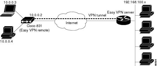
Note ![]() The diagram in Figure 1 could also represent a split tunneling connection, in which the client PCs can access public resources in the global Internet without including the corporate network in the path for the public resources.
The diagram in Figure 1 could also represent a split tunneling connection, in which the client PCs can access public resources in the global Internet without including the corporate network in the path for the public resources.
Figure 2 also illustrates the client mode of operation, in which a VPN concentrator provides destination endpoints to multiple xDSL clients. In this example, Cisco 800 series routers provide access to multiple small business clients, each of which uses IP addresses in the 10.0.0.0 private network space. The Cisco 800 series routers perform NAT or PAT translation over the VPN tunnel so that the PCs can access the destination network.
Figure 2 Cisco Easy VPN Remote Connection (Using a VPN Concentrator)
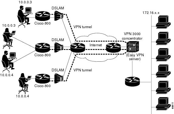
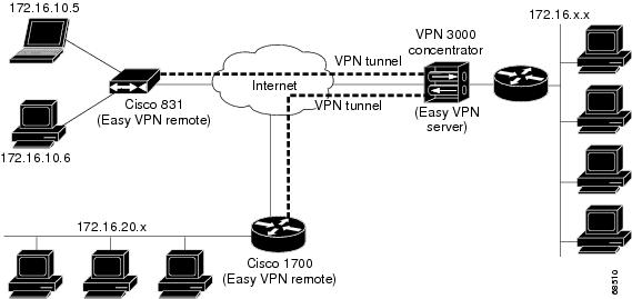
Figure 3 illustrates the network extension mode of operation. In this example, the Cisco 831 router and Cisco 1700 series router both act as Cisco Easy VPN remote devices, connecting to a Cisco VPN 3000 concentrator.
The client hosts are given IP addresses that are fully routable by the destination network over the tunnel. These IP addresses could be either in the same subnet space as the destination network or in separate subnets, assuming that the destination routers are configured to properly route those IP addresses over the tunnel.
In this example, the PCs and hosts attached to the two routers have IP addresses that are in the same address space as the destination enterprise network. The PCs connect to the Ethernet interface of the Cisco 831 router, which also has an IP address in the enterprise address space. This scenario provides a seamless extension of the remote network.
Figure 3 Cisco Easy VPN Network Extension Connection
Authentication with Cisco Easy VPN Remote
The Cisco Easy VPN Remote feature supports a two-stage process for authenticating the remote router to the central concentrator. The first step is Group Level Authentication and is part of the control channel creation. In this first stage, two types of authentication credentials can be used: either preshared keys or digital certificates. The following paragraphs provide details about these options.
The second authentication step is called Extended Authentication or Xauth. In this step, the remote side (in this case the Easy VPN router) submits a username and password to the central site router. This step is the same process as that which occurs when a user of the Cisco VPN software client on a PC enters his or her username and password to activate his or her VPN tunnel. When using the router, the difference is that the router itself is being authenticated to the network, not a PC with Cisco VPN Client software. Xauth is an optional step (it can be disabled) but is normally enabled to improve security. After Xauth is successful and the tunnel comes up, all PCs behind the Easy VPN remote router have access to the tunnel.
If Xauth is enabled, it is key to decide how to input the username and password. There are two options. The first option is to store the Xauth username and password in the configuration file of the router. This option is typically used if the router is shared between several PCs and the goal is to keep the VPN tunnel up all the time (see the section "Automatic Activation") or to have the router automatically bring up the tunnel whenever there is data to be sent (see the section "Traffic-Triggered Activation"). An example of this application is a branch office situation, in which the users in the branch office want the VPN tunnel to be available whenever they have data to send and do not want to have to do anything special to activate the VPN tunnel. If the PCs in the branch office must be individually authenticated on the basis of the ID of each user, the correct configuration is to put the Easy VPN router in Automatic Activation mode to keep the tunnel "up" all the time and to use Cisco IOS Authentication Proxy or 802.1x to authenticate the individual PCs. Because the tunnel is always up, Authentication Proxy or 802.1x can access a central site user database such as AAA/RADIUS to authenticate the individual user requests as they are submitted by PC users. (See the "Related Documents" sections "General information on IPsec and VPN" for a reference to configuring Authentication Proxy and "802.1x authentication" for a reference to configuring 802.1x authentication.)
The second option for entry of the Xauth username and password is not to store it on the router. Instead, a PC user who is connected to the router is presented with a special web page that allows the user to manually enter the username and password (see the section "Manual Activation"). The router sends the username and password to the central site concentrator, and if the username and password are correct, the tunnel comes up. The typical application for this configuration is a teleworker network. The teleworker wants to control when the tunnel is up and has to enter his or her personal user credentials (which could include one-time passwords) to activate the tunnel. Also, the network administrator may want teleworker tunnels up only when someone is using them to conserve resources on the central concentrators. (See the section "Web-Based Activation" for details about this configuration.)
The Xauth username and password can also be manually entered from the command-line interface (CLI) of the router. This method is not recommended for most situations because the user must first log in to the router (and needs a user ID on the router to do so). However, it can be useful for network administrators during troubleshooting.
Use of Preshared Keys
Using preshared keys, each peer is aware of the key of the other peer. Preshared keys are displayed in running configurations, so they can be seen by anyone (referred to as clear format). When a more secure type of authentication is required, Cisco software also supports another type of preshared key: the encrypted preshared key.
Using an encrypted preshared key for authentication allows you to securely store plain-text passwords in type 6 (encrypted) format in NVRAM. A group preshared key can be preconfigured on both VPN-tunnel peers. The encrypted form of the keyword can be seen in the running configuration, but the actual keyword is not visible. (For more information about encrypted preshared keys, see Encrypted Preshared Key.)
Use of Digital Certificates
Digital certificates provide for the support of Rivest, Shamir, and Adelman (RSA) signatures on Easy VPN remote devices. The support is provided through a RSA certificate that can be stored on or off the remote device.
Note ![]() The recommended timeout for Easy VPN using digital certificates is 40 seconds.
The recommended timeout for Easy VPN using digital certificates is 40 seconds.
For more information about digital certificates, see the Easy VPN Remote RSA Signature Support feature guide, Release 12.3(7)T1.
Use of Xauth
Xauth is an additional level of authentication that can be used. Xauth is applicable when either group preshared keys or digital certificates are used. Xauth credentials can be entered using a web interface manager, such as Security Device Manager (SDM), or using the CLI. (See the section "Cisco Easy VPN Remote Web Managers.")
The Save Password feature allows the Xauth username and password to be saved in the Easy VPN Remote configuration so that you are not required to enter the username and password manually. One-Time Passwords (OTPs) are not supported by the Save Password feature and must be entered manually when Xauth is requested. The Easy VPN server must be configured to "Allow Saved Passwords." (For more information about how to configure the Save Password feature, see the section "Dead Peer Detection Periodic Message Option.")
Xauth is controlled by the Easy VPN server. When the Cisco IOS Easy VPN server requests Xauth authentication, the following messages are displayed on the console of the router:
EZVPN: Pending XAuth Request, Please enter the following command:
crypto ipsec client ezvpn xauth
When you see this message, you can provide the necessary user ID, password, and other information by entering the crypto ipsec client ezvpn connect command and responding to the prompts that follow.
The recommended Xauth timeout is 50 seconds or fewer.
Note ![]() The timeout for entering the username and password is determined by the configuration of the Cisco IOS Easy VPN server. For servers running Cisco IOS software, this timeout value is specified by the crypto isakmp xauth timeout command.
The timeout for entering the username and password is determined by the configuration of the Cisco IOS Easy VPN server. For servers running Cisco IOS software, this timeout value is specified by the crypto isakmp xauth timeout command.
Web-Based Activation
Web-Based Activation provides a user-friendly method for a remote teleworker to authenticate the VPN tunnel between his or her remote Easy VPN router and the central site router. This feature allows administrators to set up their remote LANs so that the initial HTTP request that is coming from any of the remote PCs is intercepted by the remote Easy VPN router. A login page is returned to the user, whereby the user may enter credentials to authenticate the VPN tunnel. After the VPN tunnel comes up, all users behind this remote site can access the corporate LAN without being reprompted for the username and password. Alternatively, the user may choose to bypass the VPN tunnel and connect only to the Internet, in which case a password is not required.
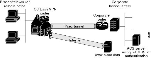
A typical application for web-based activation is a home teleworker who brings up the Easy VPN tunnel only when he or she needs to connect to the corporate LAN. If the remote teleworker is not present, other members of the household (such as a spouse or children) can use the Internet Only option to browse the Internet without activating the VPN tunnel. Figure 4 shows a typical scenario for web-based activation.
Figure 4 Typical Web-Based Activation Scenario
Note ![]() Entering the Xauth credentials brings up the tunnel for all users who are behind this remote site. After the tunnel is up, any additional PCs that are behind the remote site do not get prompted for Xauth credentials. Web-Based Activation is an authentication to bring up the VPN tunnel for all remote PCs and cannot be considered individual user authentication. Individual user authentication for VPN tunnel access is available using the Cisco IOS Authentication Proxy or 802.1x features, which can be configured on the remote Easy VPN router. (See the "Related Documents" sections "General information on IPsec and VPN" for a reference to configuring Authentication Proxy and "802.1x authentication" for a reference to configuring 802.1x authentication.)
Entering the Xauth credentials brings up the tunnel for all users who are behind this remote site. After the tunnel is up, any additional PCs that are behind the remote site do not get prompted for Xauth credentials. Web-Based Activation is an authentication to bring up the VPN tunnel for all remote PCs and cannot be considered individual user authentication. Individual user authentication for VPN tunnel access is available using the Cisco IOS Authentication Proxy or 802.1x features, which can be configured on the remote Easy VPN router. (See the "Related Documents" sections "General information on IPsec and VPN" for a reference to configuring Authentication Proxy and "802.1x authentication" for a reference to configuring 802.1x authentication.)
To configure web-based activation, see the section "Configuring Web-Based Activation."
The following sections show the various screen shots that a remote teleworker sees when the Web-Based Activation feature is turned on:
•![]() Web-Based Activation Portal Page
Web-Based Activation Portal Page
Web-Based Activation Portal Page
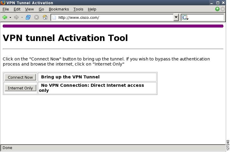
Figure 5 is an example of a web-based activation portal page. The user may choose to connect to the corporate LAN by clicking Connect Now or he or she may choose to connect only to the Internet by clicking Internet Only.
Note ![]() If the user chooses to connect only to the Internet, a password is not required.
If the user chooses to connect only to the Internet, a password is not required.
Figure 5 Portal Page
VPN Authentication Bypass
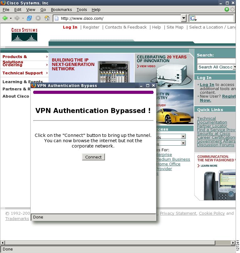
Figure 6 is an example of a web-based activation in which the user chose to connect only to the Internet by clicking the Internet Only option. This option is most useful for household members who need to browse the Internet while the remote teleworker is not available to authenticate the VPN tunnel for corporate use.
Figure 6 VPN Authentication Bypass Page
Note ![]() If the Web-Based Activation window is mistakenly closed, to connect again, a user should follow this two-step process:
If the Web-Based Activation window is mistakenly closed, to connect again, a user should follow this two-step process:
1. ![]() In a browser, type "http://routeripaddress/ezvpn/bypass" and try to connect to the URL. Entering this URL clears the bypass state that was created for your IP address (when the "Internet only" button was pressed). If you get a message saying that no such page is found, it does not matter because the only purpose of accessing the URL is to clear the bypass state.
In a browser, type "http://routeripaddress/ezvpn/bypass" and try to connect to the URL. Entering this URL clears the bypass state that was created for your IP address (when the "Internet only" button was pressed). If you get a message saying that no such page is found, it does not matter because the only purpose of accessing the URL is to clear the bypass state.
2. ![]() After clearing the bypass state, you can browse to any external site. The Connect and Bypass page appears again. You can connect to VPN by pressing the Connect button.
After clearing the bypass state, you can browse to any external site. The Connect and Bypass page appears again. You can connect to VPN by pressing the Connect button.
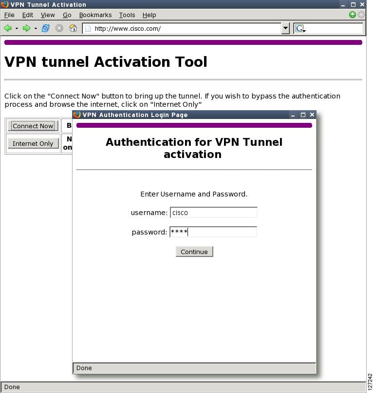
VPN Tunnel Authentication
Figure 7 is an example of a web-based activation in which the user chose to connect to the corporate LAN by entering a username and password. After the user is successfully authenticated, the Easy VPN tunnel is brought up for this remote site. If there are multiple PCs behind this remote site, none of the additional users who are connecting to the corporate LAN will be requested for the Xauth credentials because the tunnel is already up.
Figure 7 VPN Tunnel Authentication
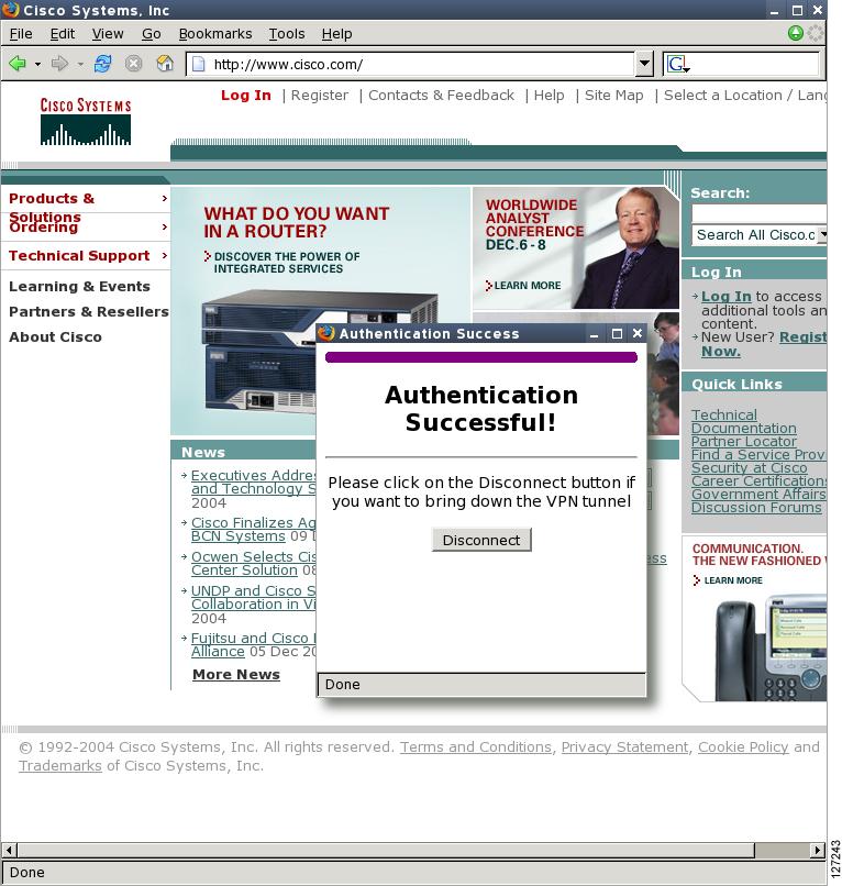
Successful Authentication
Figure 8 is an example of a successful activation. If the user chooses to deactivate the VPN tunnel, he or she should click the Disconnect button. After the IKE security association (SA) times out (the default value is 24 hours), the remote teleworker has to enter the Xauth credentials to bring up the tunnel.
Figure 8 Successful Activation
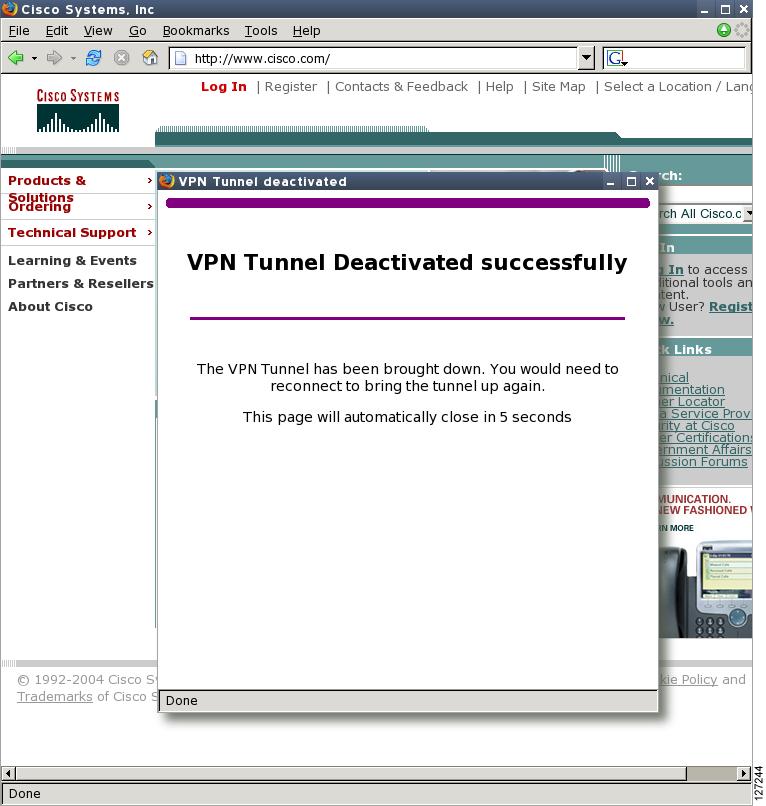
Deactivation
Figure 9 is an example of a VPN tunnel that has been deactivated successfully. The page automatically closes in 5 seconds.
Figure 9 VPN Tunnel Deactivated Successfully
802.1x Authentication
The 802.1x Authentication feature allows you to combine Easy VPN client mode operation with 802.1x authentication on Cisco IOS routers. For more information about this feature, see "802.1 Authentication" in the section "Additional References."
Tunnel Activation Options
There are three tunnel activation options:
•![]() Automatic activation
Automatic activation
•![]() Manual activation
Manual activation
•![]() Traffic-triggered activation (not available in Cisco IOS Release 12.3(11)T)
Traffic-triggered activation (not available in Cisco IOS Release 12.3(11)T)
Tunnel connect and disconnect options are available with SDM.
Automatic Activation
The Cisco Easy VPN tunnel is automatically connected when the Cisco Easy VPN Remote feature is configured on an interface. If the tunnel times out or fails, the tunnel automatically reconnects and retries indefinitely.
To specify automatic tunnel control on a Cisco Easy VPN remote device, you need to configure the crypto ipsec client ezvpn command and then the connect auto command. However, you do not need to use these two commands when you are creating a new Easy VPN remote configuration because the default is "automatic."
To disconnect or reset a particular tunnel, you should use the clear crypto ipsec client ezvpn command, or you can use SDM.
Manual Activation
The Cisco Easy VPN Remote software implements manual control of the Cisco Easy VPN tunnels so that you can establish and terminate the tunnel on demand.
To specify manual tunnel control on a Cisco Easy VPN remote device, you need to input the crypto ipsec client ezvpn command and then the connect manual command.
The manual setting means that the Cisco Easy VPN remote will wait for a command before attempting to establish the Cisco Easy VPN Remote connection. When the tunnel times out or fails, subsequent connections will also have to wait for the command.
If the configuration is manual, the tunnel is connected only after you issue the command crypto ipsec client ezvpn connect.
To disconnect or reset a particular tunnel, you should use the clear crypto ipsec client ezvpn command, or you can use SDM.
See the "Configuring Manual Tunnel Control" section for specific information on how to configure manual control of a tunnel.
Traffic-Triggered Activation
Note ![]() This feature is not available in Cisco IOS Release 12.3(11)T.
This feature is not available in Cisco IOS Release 12.3(11)T.
The Traffic-Triggered Activation feature is recommended for transactional-based VPN applications. It is also recommended for use with the Easy VPN dial backup feature for the backup Easy VPN configuration so that backup is activated only when there is traffic to send across the tunnel.
To use Access Control List (ACL) tunnel control, you must first describe the traffic that is considered "interesting." For more information about ACLs, refer to the "IP Access List Overview" chapter of the Cisco IOS Security Configuration Guide: Securing the Data Plane. To actually configure an ACL-triggered tunnel, use the crypto ipsec client ezvpn command with the connect acl command.
Dead Peer Detection Stateless Failover Support
Two options are available for configuring Dead Peer Detection Stateless Failover Support:
•![]() Backup Server List Local Configuration
Backup Server List Local Configuration
•![]() Backup Server List Auto Configuration
Backup Server List Auto Configuration
Backup Server List Local Configuration
Backup Server List Local Configuration allows users to enter multiple peer statements. With this feature configured, if the client is connecting to a peer and the negotiation fails, Easy VPN fails over to the next peer. This failover continues through the list of peers. When the last peer is reached, Easy VPN rolls over to the first peer. The IKE and IPsec SAs to the previous peer are deleted. Multiple peer statements work for both IP addresses as well as for hostnames. Setting or unsetting the peer statements will not affect the order of the peer statements.
To use this feature, use the peer command after the crypto ipsec client ezvpn command.
Backup Server List AutoConfiguration
Easy VPN remote that is based on Cisco IOS software can have up to 10 backup servers configured for redundancy. The Backup Server feature allows the Easy VPN server to "push" the backup server list to the Easy VPN remote.
The backup list allows the administrator to control the backup servers to which a specific Easy VPN remote will connect in case of failure, retransmissions, or dead peer detection (DPD) messages.
Note ![]() Before the backup server feature can work, the backup server list has to be configured on the server.
Before the backup server feature can work, the backup server list has to be configured on the server.
How a Backup Server Works
If remote A goes to server A and the connection fails, remote A goes to server B. If server B has a backup list configured, that list will override the backup server list of server A. If the connection to server B fails, remote A will continue through the backup servers that have been configured.
Note ![]() If you are in auto mode and you have a failure, you will transition automatically from server A to server B. However, if you are in manual mode, you have to configure the transition manually. To configure the transition manually, use the crypto ipsec client ezvpn command with the connect keyword.
If you are in auto mode and you have a failure, you will transition automatically from server A to server B. However, if you are in manual mode, you have to configure the transition manually. To configure the transition manually, use the crypto ipsec client ezvpn command with the connect keyword.
No new configuration is required at the Easy VPN remote to enable this feature. If you want to display the current server, you can use the show crypto ipsec client ezvpn command. If you want to find out which peers were pushed by the Easy VPN server, you can use the same command.
To troubleshoot this feature, use the debug crypto ipsec client ezvpn command. If more information is needed for troubleshooting purposes, use the debug crypto isakmp command. The show crypto ipsec client ezvpn command may also be used for troubleshooting.
Cisco Easy VPN Remote Features
The Cisco Easy VPN Remote feature is a collection of features that improves the capabilities of the Cisco Easy VPN Remote feature introduced in Cisco IOS Release 12.2(4)YA. The Cisco Easy VPN Remote feature includes the following:
•![]() Default Inside Interface—This feature supports the autoconfiguration of the default Easy VPN inside interface for Cisco 800 series routers.
Default Inside Interface—This feature supports the autoconfiguration of the default Easy VPN inside interface for Cisco 800 series routers.
•![]() Multiple Inside Interfaces—This feature allows you to configure up to eight inside interfaces on the Cisco Easy VPN remote.
Multiple Inside Interfaces—This feature allows you to configure up to eight inside interfaces on the Cisco Easy VPN remote.
•![]() Multiple Outside Interfaces—This feature allows you to configure up to four outside tunnels for outside interfaces.
Multiple Outside Interfaces—This feature allows you to configure up to four outside tunnels for outside interfaces.
•![]() VLAN Support—This feature allows VLANs to be configured as valid Easy VPN inside interfaces.
VLAN Support—This feature allows VLANs to be configured as valid Easy VPN inside interfaces.
•![]() Multiple Subnet Support—This feature allows multiple subnets from the Easy VPN inside interface to be included in the Easy VPN tunnel.
Multiple Subnet Support—This feature allows multiple subnets from the Easy VPN inside interface to be included in the Easy VPN tunnel.
•![]() NAT Interoperability Support—This feature automatically restores the NAT configuration when the IPsec VPN tunnel is disconnected.
NAT Interoperability Support—This feature automatically restores the NAT configuration when the IPsec VPN tunnel is disconnected.
•![]() Local Address Support—The Cisco Easy VPN Remote feature is enhanced to support an additional local-address attribute that specifies which interface is used to determine the IP address used to source the Easy VPN tunnel traffic.
Local Address Support—The Cisco Easy VPN Remote feature is enhanced to support an additional local-address attribute that specifies which interface is used to determine the IP address used to source the Easy VPN tunnel traffic.
•![]() Peer Hostname—When a peer is defined as a hostname, the hostname is stored and the Domain Name System (DNS) lookup is done at the time of tunnel connection.
Peer Hostname—When a peer is defined as a hostname, the hostname is stored and the Domain Name System (DNS) lookup is done at the time of tunnel connection.
•![]() Proxy DNS Server Support—This feature allows you to configure the router in a Cisco Easy VPN remote configuration to act as a proxy DNS server for LAN-connected users.
Proxy DNS Server Support—This feature allows you to configure the router in a Cisco Easy VPN remote configuration to act as a proxy DNS server for LAN-connected users.
•![]() Cisco IOS Firewall Support—This feature supports Cisco IOS Firewall configurations on all platforms.
Cisco IOS Firewall Support—This feature supports Cisco IOS Firewall configurations on all platforms.
•![]() Easy VPN Remote and Server on the Same Interface—The Easy VPN remote and Easy VPN server are supported on the same interface, which makes it possible to establish a tunnel to another Easy VPN server and terminate the Easy VPN software client on the same interface simultaneously.
Easy VPN Remote and Server on the Same Interface—The Easy VPN remote and Easy VPN server are supported on the same interface, which makes it possible to establish a tunnel to another Easy VPN server and terminate the Easy VPN software client on the same interface simultaneously.
•![]() Easy VPN Remote and Site to Site on the Same Interface—The Easy VPN Remote and site to site (crypto map) are supported on the same interface, which makes it possible to establish a tunnel to another Easy VPN server and have another site to site on the same interface simultaneously.
Easy VPN Remote and Site to Site on the Same Interface—The Easy VPN Remote and site to site (crypto map) are supported on the same interface, which makes it possible to establish a tunnel to another Easy VPN server and have another site to site on the same interface simultaneously.
•![]() Cisco Easy VPN Remote Web Managers—Users can manage the Cisco Easy VPN Remote feature on the Cisco uBR905 and Cisco uBR925 cable access routers using a built-in web interface.
Cisco Easy VPN Remote Web Managers—Users can manage the Cisco Easy VPN Remote feature on the Cisco uBR905 and Cisco uBR925 cable access routers using a built-in web interface.
•![]() Dead Peer Detection Periodic Message Option—This feature allows you to configure your router to query the liveliness of its IKE peer at regular intervals.
Dead Peer Detection Periodic Message Option—This feature allows you to configure your router to query the liveliness of its IKE peer at regular intervals.
•![]() Load Balancing—If a remote device is loaded and unable to accept more traffic, the VPN 3000 will send a notify message that contains an IP address that represents the new IKE server to which the remote should connect.
Load Balancing—If a remote device is loaded and unable to accept more traffic, the VPN 3000 will send a notify message that contains an IP address that represents the new IKE server to which the remote should connect.
•![]() Management Enhancements—This feature allows for remote management of the VPN remote.
Management Enhancements—This feature allows for remote management of the VPN remote.
•![]() PFS Support—The PFS configuration mode attribute is sent by the server if requested by the VPN remote device.
PFS Support—The PFS configuration mode attribute is sent by the server if requested by the VPN remote device.
•![]() Dial Backup—This feature allows you to configure a dial backup tunnel connection on your remote device.
Dial Backup—This feature allows you to configure a dial backup tunnel connection on your remote device.
•![]() Virtual IPsec Interface Support —This feature allows you to selectively send traffic to different Easy VPN concentrators as well as to the Internet (includes a reference to the IPsec Virtual Tunnel Interface feature.)
Virtual IPsec Interface Support —This feature allows you to selectively send traffic to different Easy VPN concentrators as well as to the Internet (includes a reference to the IPsec Virtual Tunnel Interface feature.)
•![]() Dual Tunnel Support—This feature allows you to configure multiple Easy VPN tunnels that share common inside and outside interfaces to connect two peers to two different VPN servers simultaneously.
Dual Tunnel Support—This feature allows you to configure multiple Easy VPN tunnels that share common inside and outside interfaces to connect two peers to two different VPN servers simultaneously.
•![]() Banner—The EasyVPN remote device can download a banner that has been pushed by the Easy VPN server. The banner can be used for Xauth and web-based activation. The banner is displayed when the Easy VPN tunnel is "up" on the Easy VPN remote console or as an HTML page in the case of web-based activation.
Banner—The EasyVPN remote device can download a banner that has been pushed by the Easy VPN server. The banner can be used for Xauth and web-based activation. The banner is displayed when the Easy VPN tunnel is "up" on the Easy VPN remote console or as an HTML page in the case of web-based activation.
•![]() Configuration Management Enhancements (Pushing a Configuration URL Through a Mode-Configuration Exchange)—The Easy VPN remote device can download a URL that is pushed by the Easy VPN server, allowing the Easy VPN remote device to download configuration content and apply it to the running configuration.
Configuration Management Enhancements (Pushing a Configuration URL Through a Mode-Configuration Exchange)—The Easy VPN remote device can download a URL that is pushed by the Easy VPN server, allowing the Easy VPN remote device to download configuration content and apply it to the running configuration.
•![]() Reactivate Primary Peer—This feature allows you to designate a primary peer. When an Easy VPN device fails over from the primary peer to a backup peer and the primary peer is again available, connections with the backup peer are torn down and a connection is made with the primary peer.
Reactivate Primary Peer—This feature allows you to designate a primary peer. When an Easy VPN device fails over from the primary peer to a backup peer and the primary peer is again available, connections with the backup peer are torn down and a connection is made with the primary peer.
•![]() Identical Addressing Support—This feature integrates Network Address Translation (NAT) with Easy VPN to allow remotes with overlapping internal IP addressing to connect to the Easy VPN server.
Identical Addressing Support—This feature integrates Network Address Translation (NAT) with Easy VPN to allow remotes with overlapping internal IP addressing to connect to the Easy VPN server.
•![]() cTCP Support on Easy VPN Clients-When cTCP is enabled on a remote device (client) and headend device, IKE and ESP (Protocol 50) traffic is encapsulated in the TCP header so that the firewalls in between the client and the headend device permit this traffic (considering it the same as TCP traffic).
cTCP Support on Easy VPN Clients-When cTCP is enabled on a remote device (client) and headend device, IKE and ESP (Protocol 50) traffic is encapsulated in the TCP header so that the firewalls in between the client and the headend device permit this traffic (considering it the same as TCP traffic).
Default Inside Interface
Easy VPN Remote supports the autoconfiguration of the default Easy VPN inside interface for Cisco 800 series routers. The interface Ethernet 0 is the default inside interface.
If you want to disable the default inside interface and configure another inside interface on the Cisco 800 series router, you must configure the other inside interface first and then disable the default inside interface. You can use the following command to disable the default inside interface:
no crypto ipsec client ezvpn name inside
If you did not configure the other inside interface first before disabling the default inside interface, you will receive a message such as the following (see lines three and four):
Router(config)# interface ethernet0
Router(config-if)# no crypto ipsec client ezvpn hw-client inside
Cannot remove the single inside interface unless
one other inside interface is configured
Multiple Inside Interfaces
Inside interface support is enhanced in the Cisco Easy VPN Remote feature to support multiple inside interfaces for all platforms. Inside interfaces can be configured manually with the enhanced command.:
interface interface-name
crypto ipsec client ezvpn name [outside | inside]
Note ![]() Multiple inside interfaces are supported only when the Cisco Easy VPN server and the Cisco Easy VPN client have the same type of Easy VPN configuration. In other words, both must use a Legacy Easy VPN configuration, or both must use a DVTI configuration.
Multiple inside interfaces are supported only when the Cisco Easy VPN server and the Cisco Easy VPN client have the same type of Easy VPN configuration. In other words, both must use a Legacy Easy VPN configuration, or both must use a DVTI configuration.
See the "Configuring Multiple Inside Interfaces" section for information on how to configure more than one inside interface.
Multiple inside interfaces offer the following capabilities:
•![]() Up to eight inside interfaces are supported on the Cisco 800 and Cisco 1700 series routers.
Up to eight inside interfaces are supported on the Cisco 800 and Cisco 1700 series routers.
•![]() At least one inside interface must be configured for each outside interface; otherwise, the Cisco Easy VPN Remote feature does not establish a connection.
At least one inside interface must be configured for each outside interface; otherwise, the Cisco Easy VPN Remote feature does not establish a connection.
•![]() Adding a new inside interface or removing an existing inside interface automatically resets the Cisco Easy VPN Remote connection (the currently established tunnel). You must reconnect a manually configured tunnel, and if Xauth is required by the Cisco Easy VPN server, the user is reprompted. If you have set the Cisco Easy VPN Remote configuration to connect automatically and no Xauth is required, no user input is required.
Adding a new inside interface or removing an existing inside interface automatically resets the Cisco Easy VPN Remote connection (the currently established tunnel). You must reconnect a manually configured tunnel, and if Xauth is required by the Cisco Easy VPN server, the user is reprompted. If you have set the Cisco Easy VPN Remote configuration to connect automatically and no Xauth is required, no user input is required.
•![]() Inside interfaces that are configured or the default setting can be shown by using the show crypto ipsec client ezvpn command.
Inside interfaces that are configured or the default setting can be shown by using the show crypto ipsec client ezvpn command.
Multiple Outside Interfaces
The Easy VPN Remote feature supports one Easy VPN tunnel per outside interface. You can configure up to four Easy VPN tunnels per Cisco router. Each Easy VPN tunnel can have multiple inside interfaces configured, but they cannot overlap with another Easy VPN tunnel unless dial backup is configured. For more information about dial backup, see the section "Dial Backup." To configure multiple outside interfaces, use the crypto ipsec client ezvpn command and outside keyword.
To disconnect or clear a specific tunnel, the clear crypto ipsec client ezvpn command specifies the IPsec VPN tunnel name. If there is no tunnel name specified, all existing tunnels are cleared.
See the "Configuring Multiple Outside Interfaces" section for more information on configuring more than one outside interface.
VLAN Support
Inside interface support on VLANs lets you have valid Easy VPN inside interface support on a VLAN, which was not possible before Cisco IOS Release 12.3(7)XR. With this feature, SAs can be established at connection using the VLAN subnet address or mask as a source proxy.
For the inside interface support on VLANs to work, you must define each VLAN as an Easy VPN inside interface. In addition, IPsec SAs should be established for each inside interface in the same manner as for other inside interfaces. For more information about inside and outside interfaces, see the sections "Multiple Inside Interfaces" and "Multiple Outside Interfaces."
Inside interface support on VLANs is supported only on Cisco routers that support VLANs.
Multiple Subnet Support
For situations in which you have multiple subnets connected to an Easy VPN inside interface, you can optionally include these subnets in the Easy VPN tunnel. First, you must specify the subnets that should be included by defining them in an ACL. To configure an ACL, see "Access control lists, configuring" in the "Additional References" section. Next, you have to use the acl command after the crypto ipsec client ezvpn (global) command to link your ACL to the Easy VPN configuration. Easy VPN Remote will automatically create the IPsec SAs for each subnet that is defined in the ACL as well as for the subnets that are defined on the Easy VPN inside interface.
Note ![]() Multiple subnets are not supported in client mode.
Multiple subnets are not supported in client mode.
Note ![]() This functionality is supported only when the Cisco Easy VPN server and the Cisco Easy VPN client have the same type of Easy VPN configuration. In other words, both must use a Legacy Easy VPN configuration, or both must use a DVTI configuration.
This functionality is supported only when the Cisco Easy VPN server and the Cisco Easy VPN client have the same type of Easy VPN configuration. In other words, both must use a Legacy Easy VPN configuration, or both must use a DVTI configuration.
NAT Interoperability Support
Cisco Easy VPN Remote supports interoperability with NAT. You can have a NAT configuration and a Cisco Easy VPN Remote configuration that coexist. When an IPsec VPN tunnel is down, the NAT configuration works.
In the Cisco Easy VPN Remote feature, the router automatically restores the previous NAT configuration when the IPsec VPN tunnel is torn down. The user-defined access lists are not disturbed. Users can continue to access nontunnel areas of the Internet when the tunnel times out or disconnects.
Note ![]() NAT interoperability is not supported in client mode with split tunneling.
NAT interoperability is not supported in client mode with split tunneling.
Local Address Support
The Cisco Easy VPN Remote feature is enhanced to support an additional local-address attribute. This attribute specifies which interface is used to determine the IP address that is used to source the Easy VPN Remote tunnel traffic. After specifying the interface with the local-address command, you can manually assign a static IP address to the interface or use the cable-modem dhcp-proxy interface command to automatically configure the specified interface with a public IP address. See the "Configuring Proxy DNS Server Support" section for configuration information.
Local Address Support is available for all platforms, but it is more applicable to the Cisco uBR905 and Cisco uBR925 cable access routers in conjunction with the cable-modem dhcp-proxy interface command. Typically, the loopback interface is the interface used to source tunnel traffic for the Cisco uBR905 and Cisco uBR925 cable access routers.
In a typical DOCSIS network, the Cisco uBR905 and Cisco uBR925 cable access routers are normally configured with a private IP address on the cable modem interface. In the initial Cisco Easy VPN Remote feature, a public IP address was required on the cable modem interface to support the Easy VPN remote.
In the Cisco Easy VPN Remote feature, cable providers can use the Cable DHCP Proxy feature to obtain a public IP address and assign it to the cable modem interface, which is usually the loopback interface.
For more information on the cable-modem dhcp-proxy interface command, see the Master Commands List at http://www.cisco.com/en/US/docs/ios/mcl/allreleasemcl/all_book.html.
Note ![]() The cable-modem dhcp-proxy interface command is supported only for the Cisco uBR905 and Cisco uBR925 cable access routers.
The cable-modem dhcp-proxy interface command is supported only for the Cisco uBR905 and Cisco uBR925 cable access routers.
Peer Hostname
The peer in a Cisco Easy VPN Remote configuration can be defined as an IP address or a hostname. Typically, when a peer is defined as a hostname, a DNS lookup is done immediately to get an IP address. In the Cisco Easy VPN Remote feature, the peer hostname operation is enhanced to support DNS entry changes. The text string of the hostname is stored so that the DNS lookup is done at the time of the tunnel connection, not when the peer is defined as a hostname.
See the "Configuring and Assigning the Easy VPN Remote Configuration" section for information on enabling the peer hostname functionality.
Proxy DNS Server Support
When the Easy VPN tunnel is down, the DNS addresses of the ISP or cable provider should be used to resolve DNS requests. When the WAN connection is up, the DNS addresses of the enterprise should be used.
As a way of implementing use of the DNS addresses of the cable provider when the WAN connection is down, the router in a Cisco Easy VPN Remote configuration can be configured to act as a proxy DNS server. The router, acting as a proxy DNS server for LAN-connected users, receives DNS queries from local users on behalf of the real DNS server. The DHCP server then can send out the LAN address of the router as the IP address of the DNS server. After the WAN connection comes up, the router forwards the DNS queries to the real DNS server and caches the DNS query records.
See the "Configuring Proxy DNS Server Support" section for information on enabling the proxy DNS server functionality.
Cisco IOS Firewall Support
The Cisco Easy VPN Remote feature works in conjunction with Cisco IOS Firewall configurations on all platforms.
Easy VPN Remote and Server on the Same Interface
This feature allows the Easy VPN remote and Easy VPN server to be supported on the same interface, making it possible to both establish a tunnel to another Easy VPN server and terminate the Easy VPN software client on the same interface simultaneously. A typical application would be a geographically remote location for which Easy VPN Remote is being used to connect to a corporate Easy VPN server and also to terminate local software client users.
For more information about the Easy VPN Remote and Server on the Same Interface feature, see "Easy VPN Remote and Server on the Same Interface" in the section "Additional References."
Easy VPN Remote and Site to Site on the Same Interface
This feature allows the Easy VPN remote and site to site (crypto map) to be supported on the same interface, making it possible to both establish a tunnel to another Easy VPN server and have another site to site on the same interface simultaneously. A typical application would be a third-party VPN service provider that is managing a remote router via the site-to-site tunnel and using Easy VPN Remote to connect the remote site to a corporate Easy VPN server.
For more information about the Easy VPN Remote and Site to Site on the Same Interface feature, see "Easy VPN Remote and Site to Site on the Same Interface" in the section "Additional References."
Cisco Easy VPN Remote Web Managers
Web interface managers may be used to manage the Cisco Easy VPN Remote feature. One such web interface manager is SDM, which is supported on the Cisco 830 series, Cisco 1700 series, Cisco 2600 series, Cisco 3600 series, and Cisco 3700 series routers. SDM enables you to connect or disconnect the tunnel and provides a web interface for Xauth. For more information about SDM, see Cisco Security Device Manager.
A second web interface manager is the Cisco Router Web Setup (CRWS) tool, which is supported on the Cisco 806 router. The CRWS provides a similar web interface as SDM.
A third web interface manager, Cisco Easy VPN Remote Web Manager, is used to manage the Cisco Easy VPN Remote feature for Cisco uBR905 and Cisco uBR925 cable access routers. You do not need access to the CLI to manage the Cisco Easy VPN remote connection.
The web interface managers allow you to do the following:
•![]() See the current status of the Cisco Easy VPN remote tunnel.
See the current status of the Cisco Easy VPN remote tunnel.
•![]() Connect a tunnel that is configured for manual control.
Connect a tunnel that is configured for manual control.
•![]() Disconnect a tunnel that is configured for manual control or reset a tunnel configured for automatic connection.
Disconnect a tunnel that is configured for manual control or reset a tunnel configured for automatic connection.
•![]() Be prompted for Xauth information, if needed.
Be prompted for Xauth information, if needed.
See the "Troubleshooting the VPN Connection" section for more information about Cisco Easy VPN Remote Web Manager.
Dead Peer Detection Periodic Message Option
The dead peer detection periodic message option allows you to configure your router to query the liveliness of its IKE peer at regular intervals. The benefit of this approach over the default approach (on-demand dead peer detection) is earlier detection of dead peers. For more information about the dead peer detection periodic message option, see "Dead peer detection" in the section "Additional References."
Load Balancing
When the Cisco VPN 3000 concentrator is configured for load balancing, the VPN 3000 will accept an incoming IKE request from the VPN remote on its virtual IP address. If the device is loaded and unable to accept more traffic, the VPN 3000 will send a notify message that contains an IP address that represents the new IKE server to which the remote should connect. The old connection will be torn down and a new connection established to the redirected VPN gateway.
There is no configuration required for load balancing to occur. If the VPN gateway is configured for load balancing, and it notifies the VPN remote that it is performing load balancing, the VPN remote has access to the load balancing feature.
To verify whether load balancing is occurring, use the debug crypto isakmp, debug crypto ipsec client ezvpn, and show crypto ipsec commands. To troubleshoot the load balancing process, use the show crypto ipsec command.
Management Enhancements
Management enhancements for Easy VPN remotes allow for the remote management of the VPN remote. The feature provides for the IPv4 address to be pushed by configuration mode to the VPN remote. The IPv4 address is assigned to the first available loopback interface on the VPN remote, and any existing statically defined loopbacks are not overridden. On disconnect, the address and loopback interface are removed from the list of active interfaces.
After the VPN remote is connected, the loopback interface should be accessible from the remote end of the tunnel. All PAT activities will be translated through this interface IP address.
If a loopback exists, and an IP address is associated with it and its state is unassigned, the interface is a good candidate for mode configuration address management.
Note ![]() After you assign an address to the loopback interface, if you save the configuration to NVRAM and reboot the VPN remote, the configuration address is permanently contained in the configuration. If you saved the configuration to NVRAM and rebooted the VPN remote, you must enter configuration mode and remove the IP address from the loopback interface manually.
After you assign an address to the loopback interface, if you save the configuration to NVRAM and reboot the VPN remote, the configuration address is permanently contained in the configuration. If you saved the configuration to NVRAM and rebooted the VPN remote, you must enter configuration mode and remove the IP address from the loopback interface manually.
You can use the show ip interface command with the brief keyword to verify that a loopback has been removed. The output of this show command also displays the interface.
PFS Support
The PFS configuration mode attribute is sent by the server if requested by the VPN remote device. If any subsequent connection by the remote device shows that PFS is not received by the remote, PFS will not be sent in IPsec proposal suites.
Note ![]() The PFS group that will be proposed in the IPsec proposal suites is the same as the group used for IKE.
The PFS group that will be proposed in the IPsec proposal suites is the same as the group used for IKE.
You can use the show crypto ipsec client ezvpn command to display the PFS group and to verify that you are using PFS.
Dial Backup
Note ![]() The Dial Backup feature is not available in Cisco IOS Release 12.3(11)T.
The Dial Backup feature is not available in Cisco IOS Release 12.3(11)T.
Dial backup for Easy VPN remotes allows you to configure a dial backup tunnel connection on your remote device. The backup feature is "brought up" only when real data has to be sent, eliminating the need for expensive dialup or ISDN links that must be created and maintained even when there is no traffic.
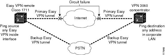
Figure 10 illustrates a typical Easy VPN remote-with-dial-backup scenario. In this scenario, Cisco 1751 remote device is attempting to connect to another Cisco 1751 (acting as a server). There is a failure in the primary Easy VPN tunnel, and the connection is rerouted through the Easy VPN backup tunnel to the Cisco 1751 server.
Figure 10 Dial Backup for Easy VPN Scenario
Dial Backup Using a Dial-on-Demand Solution
IP static route tracking enable Cisco IOS software to identify when a Point-to-Point Protocol over Ethernet (PPPoE) or IPsec VPN tunnel "goes down" and initiates a Dial-on-Demand (DDR) connection to a preconfigured destination from any alternative WAN or LAN port (for example, a T1, ISDN, analog, or auxiliary port). The failure may be caused by several catastrophic events (for example, by Internet circuit failures or peer device failure). The remote route has only a static route to the corporate network. The IP static-route-tracking feature allows an object to be tracked (using an IP address or hostname) using Internet Control Message Protocol (ICMP), TCP, or other protocols, and it installs or removes the static route on the basis of the state of the tracked object. If the tracking feature determines that Internet connectivity is lost, the default route for the primary interface is removed, and the floating static route for the backup interface is enabled.
Dial Backup Using Object Tracking
IP static route tracking must be configured for dial backup on an Easy VPN remote device to work. The object tracking configuration is independent of the Easy VPN remote dial backup configuration. (For more information about object tracking, see the feature guide Reliable Static Routing Backup Using Object Tracking.)
Easy VPN Remote Dial Backup Support Configuration
You can configure dial backup for your Easy VPN remote using two Easy VPN remote options that allow a connection to the backup Easy VPN configuration and a connection to the tracking system.
•![]() To specify the Easy VPN configuration that will be activated when backup is triggered, use the backup command after the crypto ipsec client ezvpn (global) command.
To specify the Easy VPN configuration that will be activated when backup is triggered, use the backup command after the crypto ipsec client ezvpn (global) command.
•![]() The Easy VPN remote device registers to the tracking system to get the notifications for change in the state of the object. Use the track command to inform the tracking process that the Easy VPN remote device is interested in tracking an object, which is identified by the object number. The tracking process, in turn, informs the Easy VPN remote device when the state of this object changes. This notification prompts the Easy VPN remote device when the state of this object changes. This notification prompts the Easy VPN remote device to bring up the backup connection when the tracked object state is DOWN. When the tracked object is UP again, the backup connection is torn down and the Easy VPN remote device will switch back to using the primary connection.
The Easy VPN remote device registers to the tracking system to get the notifications for change in the state of the object. Use the track command to inform the tracking process that the Easy VPN remote device is interested in tracking an object, which is identified by the object number. The tracking process, in turn, informs the Easy VPN remote device when the state of this object changes. This notification prompts the Easy VPN remote device when the state of this object changes. This notification prompts the Easy VPN remote device to bring up the backup connection when the tracked object state is DOWN. When the tracked object is UP again, the backup connection is torn down and the Easy VPN remote device will switch back to using the primary connection.
Note ![]() Only one backup configuration is supported for each primary Easy VPN configuration. Each inside interface must specify the primary and backup Easy VPN configuration.
Only one backup configuration is supported for each primary Easy VPN configuration. Each inside interface must specify the primary and backup Easy VPN configuration.
Dynamically Addressed Environments
To allow dial backup to be deployed in dynamically addressed environments, use the IP SLA Pre-Routed ICMP Echo Probe feature. (For more information about this feature, see the Release Notes for Cisco 1700 Series Routers for Cisco IOS Release 12.3(7)XR. To use the IP SLA Pre-Routed ICMP Echo Probe feature, use the icmp-echo command with the source-interface keyword.
Dial Backup Examples
For examples of dial backup configurations, see the section "Dial Backup: Examples."
Virtual IPsec Interface Support
The Virtual IPsec Interface Support feature provides a routable interface to selectively send traffic to different Easy VPN concentrators as well as to the Internet.
Before Cisco IOS Release 12.4(4)T, at the tunnel-up/tunnel-down transition, attributes that were pushed during the mode configuration had to be parsed and applied. When such attributes resulted in the configurations being applied on the interface, the existing configuration had to be overridden. With the Virtual IPsec Interface Support feature, the tunnel-up configuration can be applied to separate interfaces, making it easier to support separate features at tunnel-up time. Features that are applied to the traffic going into the tunnel can be separate from the features that are applied to traffic that is not going through the tunnel (for example, split-tunnel traffic and traffic leaving the device when the tunnel is not up). When the Easy VPN negotiation is successful, the line protocol state of the virtual-access interface gets changed to up. When the Easy VPN tunnel goes down because the security association (SA) expires or is deleted, the line protocol state of the virtual-access interfaces changes to down.
Routes act as traffic selectors in an Easy VPN virtual interface, that is, the routes replace the access list on the crypto map. In a virtual-interface configuration, Easy VPN negotiates a single IPsec SA if the Easy VPN server has been configured with a dynamic virtual IPsec interface. This single SA is created irrespective of the Easy VPN mode that is configured.
After the SA is established, routes that point to the virtual-access interface are added to direct traffic to the corporate network. Easy VPN also adds a route to the VPN concentrator so that IPsec-encapsulated packets get routed to the corporate network. A default route that points to the virtual-access interface is added in the case of a nonsplit mode. When the Easy VPN server "pushes" the split tunnel, the split tunnel subnet becomes the destination to which the routes that point to the virtual access are added. In either case, if the peer (VPN concentrator) is not directly connected, Easy VPN adds a route to the peer.
Note![]() •
•![]() Most routers that run the Cisco Easy VPN Client software have a default route configured. The default route that is configured should have a metric value greater than 1. The metric value must be greater than 1 because Easy VPN adds a default route that has a metric value of 1. The route points to the virtual-access interface so that all traffic is directed to the corporate network when the concentrator does not "push" the split tunnel attribute.
Most routers that run the Cisco Easy VPN Client software have a default route configured. The default route that is configured should have a metric value greater than 1. The metric value must be greater than 1 because Easy VPN adds a default route that has a metric value of 1. The route points to the virtual-access interface so that all traffic is directed to the corporate network when the concentrator does not "push" the split tunnel attribute.
For more information about the IPsec Virtual Tunnel Interface feature, see the document IPSec Virtual Tunnel Interface (URL link provided in the "Related Documents" section of this document ["General Information on IPsec and VPN"]).
Table 1 presents the different methods of configuring a remote device and the corresponding headend IPsec aggregator configurations. Each row represents a way to configure a remote device. The third column shows the different headend configurations that can be used with IPsec interfaces. See Table 2 for a description of terms that are used in Table 1 and Table 3.
Table 2 provides a description of the terms used in Table 1 and Table 3.
|
|
|
|---|---|
ASA |
Cisco Adaptive Security Appliance, a threat-management security appliance. |
Crypto maps |
Commonly used for configuring IPsec tunnels. The crypto map is attached to an interface. For more information on crypto maps, see the "Creating Crypto Map Sets" section in the "Configuring Security for VPNs with IPsec" chapter of the Cisco IOS Security Configuration Guide: Secure Connectivity. (URL link provided in the "Related Documents" section of this document.) |
Easy VPN dual tunnel remote device |
Two Easy VPN remote device configurations in which both are using a dynamic IPsec virtual tunnel interface. |
Easy VPN virtual interface remote device (Easy VPN virtual interface) |
Easy VPN remote configuration that configures the usage of a dynamic IPsec virtual tunnel interface. |
IPsec interface |
Consists of static and dynamic IPsec virtual interfaces. |
IPsec Virtual Tunnel Interface |
Tunnel interface that is created from a virtual template tunnel interface using mode IPsec. For more information on virtual tunnel interface configurations, see the document IPSec Virtual Tunnel Interface (URL link provided in the "Related Documents" section of this document [General Information on IPsec and VPN]). |
Legacy Easy VPN |
Easy VPN remote device configuration that uses crypto maps and does not use IPsec interfaces. |
Static IPsec virtual tunnel interface (static virtual tunnel interface) |
Tunnel interface used with mode IPsec that proposes and accepts only an "ipv4 any any" selector. For more information on static virtual tunnel interface configurations, see the document IPSec Virtual Tunnel Interface (URL link provided in the "Related Documents" section of this document ["General Information on IPsec and VPN"]). |
VPN 3000 |
Cisco VPN 3000 series routers. |
Dual Tunnel Support
Easy VPN now supports the ability to configure two easy VPN tunnels that have the same inside and outside interfaces. The feature is called the Easy VPN Dual Tunnel. Configuring multiple tunnels on a single remote device can be accomplished in a number of ways, which are listed below in Table 3 along with their configuration and usage considerations. Further discussion in this section refers to only one such method of configuring dual tunnels using Easy VPN tunnels that have virtual interfaces. This method will be referred to as Dual Tunnel Support.
In a dual-tunnel Easy VPN setup, each Easy VPN tunnel is configured using virtual IPsec interface support, as shown in the section "Virtual IPsec Interface Support." Each Easy VPN tunnel has its unique virtual interface, which is created when the Easy VPN configuration is complete.
There are two possible combinations in which the dual tunnels can be used.
•![]() Dual Easy VPN tunnels that have one tunnel using a nonsplit tunnel policy and the other tunnel using a split tunnel policy that has been pushed from the respective headend.
Dual Easy VPN tunnels that have one tunnel using a nonsplit tunnel policy and the other tunnel using a split tunnel policy that has been pushed from the respective headend.
•![]() Dual Easy VPN tunnel in which both tunnels are using an independent split tunnel policy that has been pushed from the respective headend.
Dual Easy VPN tunnel in which both tunnels are using an independent split tunnel policy that has been pushed from the respective headend.
Note ![]() It is not permitted to have dual Easy VPN tunnels in which both tunnels are using a nonsplit tunnel policy.
It is not permitted to have dual Easy VPN tunnels in which both tunnels are using a nonsplit tunnel policy.
The Easy VPN dual tunnel makes use of route injections to direct the appropriate traffic through the correct Easy VPN virtual tunnel interface. When the Easy VPN tunnel on the remote device "comes up," it "learns" the split or nonsplit policy from the headend. The Easy VPN remote device injects routes in its routing table that correspond to the nonsplit networks that have been learned. If the headend pushes a nonsplit tunnel policy to the Easy VPN remote device, the Easy VPN remote device installs a default route in its routing table that directs all traffic out of the Easy VPN virtual interface that corresponds to this Easy VPN tunnel. If the headend pushes split-tunnel networks to the remote device, the remote device installs specific routes to the split networks in its routing table, directing the traffic to these networks out of the virtual tunnel interface.
Note ![]() Dual Tunnel Easy VPN uses destination-based routing to send traffic to the respective tunnels.
Dual Tunnel Easy VPN uses destination-based routing to send traffic to the respective tunnels.
Output features can be applied to this virtual interface. Examples of such output features are Cisco IOS quality of service and Cisco IOS Firewall. These features must be configured on the virtual template that is configured in the Easy VPN client configuration.
Table 3 explains how this feature should be used. See Table 2 for a description of terms that are used in Table 1 and Table 3.
Banner
The Easy VPN server pushes a banner to the Easy VPN remote device. The Easy VPN remote device can use the banner during Xauth and web-based activation. The Easy VPN remote device displays the banner the first time that the Easy VPN tunnel is brought up.
The banner is configured under group configuration on the Easy VPN server.
Configuration Management Enhancements (Pushing a Configuration URL Through a Mode-Configuration Exchange)
After this feature has been configured on the server using the commands configuration url and configuration version (after use of the crypto isakmp client configuration group command), the server can "push" the configuration URL and configuration version number to the Easy VPN remote device. With this information, the Easy VPN remote device can download the configuration content and apply it to its running configuration. For more information about this feature, see the section "Configuration Management Enhancements" in the Easy VPN Server feature module.
Reactivate Primary Peer
The Reactivate Primary Peer feature allows a default primary peer to be defined. The default primary peer (a server) is one that is considered better than other peers for reasons such as lower cost, shorter distance, or more bandwidth. With this feature configured, if Easy VPN fails over during Phase 1 SA negotiations from the primary peer to the next peer in its backup list, and if the primary peer is again available, the connections with the backup peer are torn down and the connection is again made with the primary peer.
Dead Peer Detection is one of the mechanisms that acts as a trigger for primary peer reactivation. Idle timers that are configured under Easy VPN is another triggering mechanism. When configured, the idle timer detects inactivity on the tunnel and tears it down. A subsequent connect (which is immediate in auto mode) is attempted with the primary preferred peer rather than with the peer last used.
Note ![]() Only one primary peer can be defined.
Only one primary peer can be defined.
Identical Addressing Support
The Identical Addressing Support feature supports identically addressed LANs on Easy VPN remotes. Network resources, such as printers and web servers on the LAN side of the EasyVPN remotes, that have overlapping addressing with other Easy VPN remotes are now reachable. The Easy VPN Remote feature was enhanced to work with NAT to provide this functionality.
•![]() The Easy VPN server requires no changes to support the Identical Addressing Support feature.
The Easy VPN server requires no changes to support the Identical Addressing Support feature.
•![]() The Identical Addressing Support feature is supported only in network extension modes (network-extension and network-plus).
The Identical Addressing Support feature is supported only in network extension modes (network-extension and network-plus).
•![]() Virtual tunnel interfaces must be configured on the Easy VPN remote before using the Identical Addressing Support feature.
Virtual tunnel interfaces must be configured on the Easy VPN remote before using the Identical Addressing Support feature.
Figure 11 shows an example of the Identical Addressing Support feature configuration.
Figure 11 Identical Addressing Support
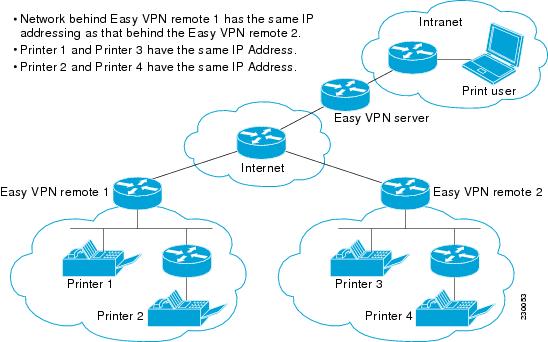
The Identical Addressing Support feature can be configured with the following command and enhanced commands:
crypto ipsec client ezvpn <name>
Enhanced commands
•![]() nat acl {acl-name | acl-number}—Enables split tunneling for the traffic specified by the ACL name or the ACL number.
nat acl {acl-name | acl-number}—Enables split tunneling for the traffic specified by the ACL name or the ACL number.
–![]() The acl-name argument is the name of the ACL.
The acl-name argument is the name of the ACL.
–![]() The acl-number argument is the number of the ACL.
The acl-number argument is the number of the ACL.
•![]() nat allow—Allows NAT to be integrated with Cisco Easy VPN.
nat allow—Allows NAT to be integrated with Cisco Easy VPN.
For detailed steps on how to configure Identical Addressing Support, see "Configuring Identical Addressing Support."
cTCP Support on Easy VPN Clients
The Cisco Tunneling Control Protocol (cTCP) feature can be used for situations in which an Easy VPN client (remote device) is operating in an environment in which standard IPsec does not function or in which it does not function transparently without modification to existing firewall rules. These situations include the following:
•![]() Small office or home office router performing Network Address Translation (NAT) or Port Address Translation (PAT)
Small office or home office router performing Network Address Translation (NAT) or Port Address Translation (PAT)
•![]() PAT-provided IP address behind a larger router (for example, in a corporation)
PAT-provided IP address behind a larger router (for example, in a corporation)
•![]() Non-NAT firewall (packet filtering or stateful)
Non-NAT firewall (packet filtering or stateful)
•![]() Proxy server
Proxy server
Figure 12 illustrates how IPsec traffic that is tunneled inside the cTCP traverses Network Address Translation (NAT) and the firewall (see the dashed line).
Figure 12 cTCP on an Easy VPN Remote Device
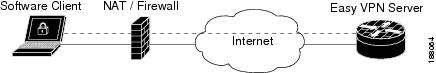
For detailed steps on how to configure cTCP on Easy VPN remote devices, see the section "Configuring cTCP on an Easy VPN Client."
For more information about cTCP support on Easy VPN remote devices, including configuration and troubleshooting examples, see "cTCP on Cisco Easy VPN remote devices" in the section "Related Documents."
Easy VPN Server on a VPN 3000 Series Concentrator
This section describes the guidelines required to configure the Cisco VPN 3000 series concentrator for use with the Cisco Easy VPN Remote feature. As a general rule, you can use the default configuration except for IP addresses, server addresses, routing configurations, and for the following parameters and options:
•![]() Peer Configuration on a Cisco Easy VPN Remote Using the Hostname
Peer Configuration on a Cisco Easy VPN Remote Using the Hostname
•![]() Interactive Hardware Client Authentication Version 3.5
Interactive Hardware Client Authentication Version 3.5
Note ![]() You must be using Cisco VPN 3000 series concentrator software Release 3.11 or later to support Cisco Easy VPN software clients and remotes.
You must be using Cisco VPN 3000 series concentrator software Release 3.11 or later to support Cisco Easy VPN software clients and remotes.
Peer Configuration on a Cisco Easy VPN Remote Using the Hostname
After you have configured the Cisco Easy VPN server on the VPN 3000 concentrator to use hostname as its identity, you must configure the peer on the Cisco Easy VPN remote using the hostname. You can either configure DNS on the client to resolve the peer hostname or configure the peer hostname locally on the client using the ip host command. As an example, you can configure the peer hostname locally on an Easy VPN remote as follows:
ip host crypto-gw.cisco.com 10.0.0.1
Or you can configure the Easy VPN remote to use the hostname with the peer command and hostname argument, as follows:
peer crypto-gw.cisco.com.
Interactive Hardware Client Authentication Version 3.5
The Cisco Easy VPN Remote feature does not support the Interactive Hardware Client Authentication Version 3.5 feature. This feature must be disabled. You can disable the feature on the VPN 3000 series concentrator by clicking the HW Client tab on the Configuration | User Management | Base Group screen.
IPsec Tunnel Protocol
IPsec Tunnel Protocol enables the IPsec tunnel protocol so that it is available for users. The IPsec Tunnel Protocol is configured on the Cisco VPN 3000 series concentrator by clicking the General tab on the Configuration | User Management | Base Group screen.
IPsec Group
IPsec group configures the Cisco VPN 3000 series concentrator with a group name and password that match the values configured for the Cisco Easy VPN remote configuration on the router. These values are configured on the router with the group group-name key group-key command and arguments. The values are configured on the Cisco VPN 3000 series concentrator using the Configuration | User Management | Groups screen.
Group Lock
If you are defining multiple users in multiple groups on the VPN 3000 series concentrator, you must check the Group Lock box in the IPsec tab to prevent users in one group from logging in with the parameters of another group. For example, if you have configured one group for split tunneling access and another group without split tunneling access, clicking the Group Lock box prevents users in the second group from gaining access to the split tunneling features. The Group Lock checkbox appears in the IPsec tab in the Configuration | User Management | Base Group screen and in the IPsec tab in the Configuration | User Management | Groups | Add/Modify screens.
Xauth
To use Xauth, set the Authentication parameter to None. The Authentication parameter appears in the IPsec tab in the Configuration | User Management | Base Group screen and in the IPsec tab in the Configuration | User Management | Groups | Add/Modify screens.
Split Tunneling
The Configuration | User Management | Base Group, Mode Configuration Parameters Tab screen includes a Split Tunnel option with a checkbox that says "Allow the networks in the list to bypass the tunnel."
IKE Proposals
The Cisco VPN 3000 series concentrator is preconfigured with a default IKE proposal, CiscoVPNClient-3DES-MD5, that can be used with Cisco Easy VPN remotes. This IKE proposal supports preshared keys with Xauth using the MD5/HMAC-128 algorithm and Diffie-Hellman Group 2.
This IKE proposal is active by default, but you should verify that it is still an active proposal using the Configuration | System | Tunneling Protocols | IPsec | IKE Proposals screen.
In addition, as part of configuring the Cisco VPN 3000 series concentrator—for the Cisco Easy VPN Remote image, you do not need to create a new IPsec SA. Use the default IKE and Easy VPN remote lifetime configured on the Cisco VPN 3000 series concentrator.
Note ![]() You can also use the default IKE proposals IKE-DES-MD5 and IKE-3DES-MD5, but they do not enable Xauth support by default.
You can also use the default IKE proposals IKE-DES-MD5 and IKE-3DES-MD5, but they do not enable Xauth support by default.
New IPsec SA
You can create a new IPsec SA. Cisco Easy VPN clients use a SA having the following parameters:
•![]() Authentication Algorithm=ESP/MD5/HMAC-128
Authentication Algorithm=ESP/MD5/HMAC-128
•![]() Encryption Algorithm=DES-56 or 3DES-168 (recommended)
Encryption Algorithm=DES-56 or 3DES-168 (recommended)
•![]() Encapsulation Mode=Tunnel
Encapsulation Mode=Tunnel
•![]() IKE Proposal=CiscoVPNClient-3DES-MD5 (preferred)
IKE Proposal=CiscoVPNClient-3DES-MD5 (preferred)
The Cisco VPN 3000 series concentrator is preconfigured with several default security associations (SAs), but they do not meet the IKE proposal requirements. To use an IKE proposal of CiscoVPNClient-3DES-MD5, copy the ESP/IKE-3DES-MD5 SA and modify it to use CiscoVPNClient-3DES-MD5 as its IKE proposal. An IKE proposal is configured on the VPN 3000 series concentrator using the Configuration | Policy Management | Traffic Management | Security Associations screen.
How to Configure Cisco Easy VPN Remote
•![]() Troubleshooting the VPN Connection
Troubleshooting the VPN Connection
Remote Tasks
•![]() Configuring and Assigning the Easy VPN Remote Configuration (required)
Configuring and Assigning the Easy VPN Remote Configuration (required)
•![]() Verifying the Cisco Easy VPN Configuration (optional)
Verifying the Cisco Easy VPN Configuration (optional)
•![]() Configuring Save Password (optional)
Configuring Save Password (optional)
•![]() Configuring Manual Tunnel Control (optional)
Configuring Manual Tunnel Control (optional)
•![]() Configuring Automatic Tunnel Control (optional)
Configuring Automatic Tunnel Control (optional)
•![]() Configuring Multiple Inside Interfaces (optional)
Configuring Multiple Inside Interfaces (optional)
•![]() Configuring Multiple Outside Interfaces (optional)
Configuring Multiple Outside Interfaces (optional)
•![]() Configuring Multiple Subnet Support (optional)
Configuring Multiple Subnet Support (optional)
•![]() Configuring Proxy DNS Server Support (optional)
Configuring Proxy DNS Server Support (optional)
•![]() Configuring Dial Backup (optional)
Configuring Dial Backup (optional)
•![]() Configuring the DHCP Server Pool (required)
Configuring the DHCP Server Pool (required)
•![]() Resetting a VPN Connection (optional)
Resetting a VPN Connection (optional)
•![]() Monitoring and Maintaining VPN and IKE Events (optional)
Monitoring and Maintaining VPN and IKE Events (optional)
•![]() Configuring a Virtual Interface (optional)
Configuring a Virtual Interface (optional)
•![]() Troubleshooting Dual Tunnel Support (optional)
Troubleshooting Dual Tunnel Support (optional)
•![]() Configuring Reactivate (a Default) Primary Peer (optional)
Configuring Reactivate (a Default) Primary Peer (optional)
•![]() Configuring Identical Addressing Support (optional)
Configuring Identical Addressing Support (optional)
•![]() Configuring cTCP on an Easy VPN Client (optional)
Configuring cTCP on an Easy VPN Client (optional)
•![]() Restricting Traffic When a Tunnel Is Down (optional)
Restricting Traffic When a Tunnel Is Down (optional)
Configuring and Assigning the Easy VPN Remote Configuration
The router acting as the Easy VPN remote must create a Cisco Easy VPN Remote configuration and assign it to the outgoing interface. To configure and assign the remote configuration, perform the following steps.
SUMMARY STEPS
1. ![]() enable
enable
2. ![]() configure terminal
configure terminal
3. ![]() crypto ipsec client ezvpn name
crypto ipsec client ezvpn name
4. ![]() group group-name key group-key
group group-name key group-key
5. ![]() peer [ip-address | hostname]
peer [ip-address | hostname]
6. ![]() mode {client | network-extension}
mode {client | network-extension}
7. ![]() exit
exit
8. ![]() interface interface
interface interface
9. ![]() crypto ipsec client ezvpn name [outside]
crypto ipsec client ezvpn name [outside]
10. ![]() exit
exit
11. ![]() exit
exit
DETAILED STEPS
Verifying the Cisco Easy VPN Configuration
To verify that the Cisco Easy VPN Remote configuration has been correctly configured, that the configuration has been assigned to an interface, and that the IPsec VPN tunnel has been established, perform the following steps.
SUMMARY STEPS
1. ![]() show crypto ipsec client ezvpn
show crypto ipsec client ezvpn
2. ![]() show ip nat statistics
show ip nat statistics
DETAILED STEPS
Step 1 ![]() Display the current state of the Cisco Easy VPN Remote connection using the show crypto ipsec client ezvpn command. The following is typical output for a Cisco 1700 series router using client mode:
Display the current state of the Cisco Easy VPN Remote connection using the show crypto ipsec client ezvpn command. The following is typical output for a Cisco 1700 series router using client mode:
Router# show crypto ipsec client ezvpn
Tunnel name : hw1
Inside interface list: FastEthernet0/0, Serial0/0,
Outside interface: Serial1/0
Current State: IPSEC_ACTIVE
Last Event: SOCKET_UP
Address: 10.0.0.5
Mask: 255.255.255.255
Default Domain: cisco.com
Tunnel name : hw2
Inside interface list: Serial0/1,
Outside interface: Serial1/1
Current State: IPSEC_ACTIVE
Last Event: SOCKET_UP
Default Domain: cisco.com
Step 2 ![]() Display the NAT or PAT configuration that was automatically created for the VPN connection using the show ip nat statistics command. The "Dynamic mappings" field of this display gives the details for the NAT or PAT translation that is occurring on the VPN tunnel.
Display the NAT or PAT configuration that was automatically created for the VPN connection using the show ip nat statistics command. The "Dynamic mappings" field of this display gives the details for the NAT or PAT translation that is occurring on the VPN tunnel.
Router# show ip nat statistics
Total active translations: 0 (0 static, 0 dynamic; 0 extended)
Outside interfaces:
cable-modem0
Inside interfaces:
Ethernet0
Hits: 1489 Misses: 1
Expired translations: 1
Dynamic mappings:
-- Inside Source
access-list 198 pool enterprise refcount 0
pool enterprise: netmask 255.255.255.0
start 192.168.1.90 end 192.168.1.90
type generic, total addresses 1, allocated 0 (0%), misses 0\
If you are seeing IPSEC_ACTIVE in your output at this point, everything is operating as expected.
Configuring Save Password
To configure the Save Password feature, perform the following steps.
SUMMARY STEPS
1. ![]() enable
enable
2. ![]() configure terminal
configure terminal
3. ![]() password encryption aes
password encryption aes
4. ![]() crypto ipsec client ezvpn name
crypto ipsec client ezvpn name
5. ![]() username name password {0 | 6} {password}
username name password {0 | 6} {password}
6. ![]() exit
exit
7. ![]() show running-config
show running-config
DETAILED STEPS
Configuring Manual Tunnel Control
Note ![]() CLI is one option for connecting the tunnel. The preferred method is via the web interface (using SDM).
CLI is one option for connecting the tunnel. The preferred method is via the web interface (using SDM).
To configure control of IPsec VPN tunnels manually so that you can establish and terminate the IPsec VPN tunnels on demand, perform the following steps.
SUMMARY STEPS
1. ![]() enable
enable
2. ![]() configure terminal
configure terminal
3. ![]() crypto ipsec client ezvpn name
crypto ipsec client ezvpn name
4. ![]() connect [auto | manual]
connect [auto | manual]
5. ![]() exit
exit
6. ![]() exit
exit
7. ![]() crypto ipsec client ezvpn connect name
crypto ipsec client ezvpn connect name
DETAILED STEPS
Configuring Automatic Tunnel Control
To configure automatic tunnel control, perform the following steps.
SUMMARY STEPS
1. ![]() enable
enable
2. ![]() configure terminal
configure terminal
3. ![]() crypto ipsec client ezvpn name
crypto ipsec client ezvpn name
4. ![]() connect [auto | manual]
connect [auto | manual]
5. ![]() exit
exit
6. ![]() exit
exit
7. ![]() crypto ipsec client ezvpn connect name
crypto ipsec client ezvpn connect name
DETAILED STEPS
Configuring Multiple Inside Interfaces
You can configure up to three inside interfaces for all platforms.
Note ![]() Multiple inside interfaces are supported only when the Cisco Easy VPN server and the Cisco Easy VPN client have the same type of Easy VPN configuration. In other words, both must use a Legacy Easy VPN configuration, or both must use a DVTI configuration.
Multiple inside interfaces are supported only when the Cisco Easy VPN server and the Cisco Easy VPN client have the same type of Easy VPN configuration. In other words, both must use a Legacy Easy VPN configuration, or both must use a DVTI configuration.
You need to manually configure each inside interface using the following procedure.
SUMMARY STEPS
1. ![]() enable
enable
2. ![]() configure terminal
configure terminal
3. ![]() interface interface-name
interface interface-name
4. ![]() exit
exit
5. ![]() crypto ipsec client ezvpn name [outside | inside]
crypto ipsec client ezvpn name [outside | inside]
6. ![]() interface interface-name
interface interface-name
7. ![]() exit
exit
8. ![]() crypto ipsec client ezvpn name [outside | inside]
crypto ipsec client ezvpn name [outside | inside]
DETAILED STEPS
Configuring Multiple Outside Interfaces
You can configure multiple tunnels for outside interfaces, setting up a tunnel for each outside interface. You can configure a maximum of four tunnels using the following procedure for each outside interface.
SUMMARY STEPS
1. ![]() enable
enable
2. ![]() configure terminal
configure terminal
3. ![]() interface interface-name
interface interface-name
4. ![]() exit
exit
5. ![]() crypto ipsec client ezvpn name [outside | inside]
crypto ipsec client ezvpn name [outside | inside]
6. ![]() interface interface-name
interface interface-name
7. ![]() exit
exit
8. ![]() crypto ipsec client ezvpn name [outside | inside]
crypto ipsec client ezvpn name [outside | inside]
DETAILED STEPS
Configuring Multiple Subnet Support
When configuring multiple subnet support, you must first configure an access list to define the actual subnets to be protected. Each source subnet or mask pair indicates that all traffic that is sourced from this network to any destination is protected by IPsec. For information about configuring ACLs, see "Access Control List Configuration" in the section "Additional References."
Note ![]() Multiple subnets are not supported in client mode. This functionality is supported only when the Cisco Easy VPN server and the Cisco Easy VPN client have the same type of Easy VPN configuration. In other words, both must use a Legacy Easy VPN configuration, or both must use a dVTI configuration.
Multiple subnets are not supported in client mode. This functionality is supported only when the Cisco Easy VPN server and the Cisco Easy VPN client have the same type of Easy VPN configuration. In other words, both must use a Legacy Easy VPN configuration, or both must use a dVTI configuration.
After you have defined the subnets, you must configure the crypto IPsec client EZVPN profile to use the ACLs.
SUMMARY STEPS
1. ![]() enable
enable
2. ![]() configure terminal
configure terminal
3. ![]() interface interface-name
interface interface-name
4. ![]() exit
exit
5. ![]() crypto ipsec client ezvpn name
crypto ipsec client ezvpn name
6. ![]() acl {acl-name | acl-number}
acl {acl-name | acl-number}
DETAILED STEPS
Configuring Proxy DNS Server Support
As a way of implementing the use of the DNS addresses of the ISP when the WAN connection is down, the router in a Cisco Easy VPN remote configuration can be configured to act as a proxy DNS server. To enable the proxy DNS server functionality with the ip dns server command, perform the following steps.
SUMMARY STEPS
1. ![]() enable
enable
2. ![]() configure terminal
configure terminal
3. ![]() ip dns server
ip dns server
DETAILED STEPS
What to Do Next
After configuring the router, you configure the Cisco IOS Easy VPN server as follows:
•![]() Under the crypto isakmp client configuration group command, configure the dns command as in the following example:
Under the crypto isakmp client configuration group command, configure the dns command as in the following example:
dns A.B.C.D A1.B1.C1.D1
These DNS server addresses should be pushed from the server to the Cisco Easy VPN remote and dynamically added to or deleted from the running configuration of the router.
For information about general DNS server functionality in Cisco IOS software applications, see the "Configuring DNS" chapter of the Catalyst 6500 Series Software Configuration Guide and the Configuring DNS on Cisco Routers design technical note.
Configuring Dial Backup
Note ![]() The Dial Backup feature is not available in Cisco IOS Release 12.3(11)T.
The Dial Backup feature is not available in Cisco IOS Release 12.3(11)T.
To configure dial backup, perform the following steps.
SUMMARY STEPS
1. ![]() Create the Easy VPN backup configuration.
Create the Easy VPN backup configuration.
2. ![]() Add the backup command details to the primary configuration.
Add the backup command details to the primary configuration.
3. ![]() Apply the backup Easy VPN configuration to the dial backup outside interface.
Apply the backup Easy VPN configuration to the dial backup outside interface.
4. ![]() Apply the Easy VPN profile to the inside interfaces.
Apply the Easy VPN profile to the inside interfaces.
DETAILED STEPS
|
|
|
|
|---|---|---|
Step 1 |
Create the Easy VPN dial backup configuration. |
For details about the backup configuration, see the section "Dial Backup." |
Step 2 |
Add the backup command details to the primary configuration. |
Use the backup command and track keyword of the crypto ipsec client ezvpn command. |
Step 3 |
Apply the backup Easy VPN configuration to the dial backup outside interface (for example, serial, async, or dialer). |
For details about applying the backup configuration to the dial backup outside interface, see the section "Configuring Multiple Outside Interfaces." |
Step 4 |
Apply the Easy VPN profile to the inside interfaces (there can be more than one). |
For details about applying the Easy VPN profile to the inside interfaces, see the section "Configuring Multiple Inside Interfaces." |
Configuring the DHCP Server Pool
To configure the Dynamic Host Configuration Protocol (DHCP) server pool, see DHCP Features Roadmap.
Resetting a VPN Connection
To reset the VPN connection, perform the following steps. The clear commands can be configured in any order or independent of one another.
SUMMARY STEPS
1. ![]() enable
enable
2. ![]() clear crypto ipsec client ezvpn
clear crypto ipsec client ezvpn
3. ![]() clear crypto sa
clear crypto sa
4. ![]() clear crypto isakmp
clear crypto isakmp
DETAILED STEPS
Monitoring and Maintaining VPN and IKE Events
To monitor and maintain VPN and IKE events, perform the following steps.
SUMMARY STEPS
1. ![]() enable
enable
2. ![]() debug crypto ipsec client ezvpn
debug crypto ipsec client ezvpn
3. ![]() debug crypto ipsec
debug crypto ipsec
4. ![]() debug crypto isakmp
debug crypto isakmp
SUMMARY STEPS
Configuring a Virtual Interface
Before the virtual interface is configured, ensure that the Easy VPN profile is not applied on any outside interface. Remove the Easy VPN profile from the outside interface and then configure the virtual interface. To configure a virtual interface, perform the following steps.
SUMMARY STEPS
1. ![]() enable
enable
2. ![]() configure terminal
configure terminal
3. ![]() interface virtual-template number type type-of-virtual-template
interface virtual-template number type type-of-virtual-template
4. ![]() tunnel mode ipsec ipv4
tunnel mode ipsec ipv4
5. ![]() exit
exit
6. ![]() crypto ipsec client ezvpn name
crypto ipsec client ezvpn name
7. ![]() virtual-interface virtual-template-number
virtual-interface virtual-template-number
DETAILED STEPS
Troubleshooting Dual Tunnel Support
The following debug and show commands may be used to troubleshoot your dual-tunnel configuration.
SUMMARY STEPS
1. ![]() enable
enable
2. ![]() debug crypto ipsec client ezvpn
debug crypto ipsec client ezvpn
3. ![]() debug ip policy
debug ip policy
4. ![]() show crypto ipsec client ezvpn
show crypto ipsec client ezvpn
5. ![]() show ip interface
show ip interface
DETAILED STEPS
Configuring Reactivate (a Default) Primary Peer
To configure a default primary peer, perform the following steps.
SUMMARY STEPS
1. ![]() enable
enable
2. ![]() configure terminal
configure terminal
3. ![]() crypto ipsec client ezvpn name
crypto ipsec client ezvpn name
4. ![]() peer {ip-address | hostname} [default]
peer {ip-address | hostname} [default]
5. ![]() idle-time idle-time
idle-time idle-time
DETAILED STEPS
Configuring Identical Addressing Support
Configuring Identical Addressing Support comprises the following tasks:
•![]() Defining the Easy VPN remote in network-extension mode and enabling nat allow.
Defining the Easy VPN remote in network-extension mode and enabling nat allow.
•![]() Assigning the Cisco Easy VPN Remote configuration to the Outside interface.
Assigning the Cisco Easy VPN Remote configuration to the Outside interface.
•![]() Creating a loopback interface and assigning the Cisco Easy VPN Remote configuration to the Inside interface of the loopback interface.
Creating a loopback interface and assigning the Cisco Easy VPN Remote configuration to the Inside interface of the loopback interface.
•![]() Configuring a one-to-one static NAT translation for each host that needs to be accessible from the EasyVPN server-side network or from other client locations.
Configuring a one-to-one static NAT translation for each host that needs to be accessible from the EasyVPN server-side network or from other client locations.
•![]() Configuring dynamic overloaded NAT or PAT using an access list for all the desired VPN traffic. The NAT or PAT traffic is mapped to the Easy VPN inside interface IP address.
Configuring dynamic overloaded NAT or PAT using an access list for all the desired VPN traffic. The NAT or PAT traffic is mapped to the Easy VPN inside interface IP address.
•![]() And, if split-tunneling is required, using the nat acl command to enable split-tunneling for the traffic specified by the acl-name or the acl-number argument. The ACL is the same as the ACL used by the NAT or PAT mapping in the preceding bullet item.
And, if split-tunneling is required, using the nat acl command to enable split-tunneling for the traffic specified by the acl-name or the acl-number argument. The ACL is the same as the ACL used by the NAT or PAT mapping in the preceding bullet item.
To configure Identical Addressing Support, perform the following steps on your router.
Prerequisites
Easy VPN Remote must be configured in network extension mode before you can configure the Identical Addressing Support feature.
SUMMARY STEPS
1. ![]() enable
enable
2. ![]() configure terminal
configure terminal
3. ![]() crypto ipsec client ezvpn name
crypto ipsec client ezvpn name
4. ![]() mode network-extension
mode network-extension
5. ![]() nat allow
nat allow
6. ![]() exit
exit
7. ![]() interface interface
interface interface
8. ![]() crypto ipsec client ezvpn name outside
crypto ipsec client ezvpn name outside
9. ![]() exit
exit
10. ![]() interface interface
interface interface
11. ![]() ip address ip mask
ip address ip mask
12. ![]() crypto ipsec client ezvpn name inside
crypto ipsec client ezvpn name inside
13. ![]() exit
exit
14. ![]() ip nat inside source static local-ip global-ip
ip nat inside source static local-ip global-ip
15. ![]() ip nat inside source list {acl-name | acl-number} interface interface overload
ip nat inside source list {acl-name | acl-number} interface interface overload
16. ![]() crypto ipsec client ezvpn name
crypto ipsec client ezvpn name
17. ![]() nat acl {acl-name | acl-number}
nat acl {acl-name | acl-number}
18. ![]() exit
exit
19. ![]() exit
exit
DETAILED STEPS
Configuring cTCP on an Easy VPN Client
To configure cTCP on an Easy VPN client (remote device), perform the following steps.
SUMMARY STEPS
1. ![]() enable
enable
2. ![]() configure terminal
configure terminal
3. ![]() crypto ctcp [keepalive number-of-seconds | port port-number]
crypto ctcp [keepalive number-of-seconds | port port-number]
4. ![]() crypto ipsec client ezvpn name
crypto ipsec client ezvpn name
5. ![]() ctcp port port-number
ctcp port port-number
DETAILED STEPS
Restricting Traffic When a Tunnel Is Down
To restrict the client from sending traffic in clear text when a tunnel is down, perform the following steps.
SUMMARY STEPS
1. ![]() enable
enable
2. ![]() configure terminal
configure terminal
3. ![]() crypto ipsec client ezvpn name
crypto ipsec client ezvpn name
4. ![]() flow allow acl [name | number]
flow allow acl [name | number]
DETAILED STEPS
Easy VPN Server Tasks
•![]() Configuring a Cisco IOS Easy VPN Server (required)
Configuring a Cisco IOS Easy VPN Server (required)
•![]() Configuring an Easy VPN Server on a Cisco PIX Firewall (optional)
Configuring an Easy VPN Server on a Cisco PIX Firewall (optional)
Configuring a Cisco IOS Easy VPN Server
For information about configuring the Easy VPN Server, see the following document:
Configuring an Easy VPN Server on a Cisco PIX Firewall
For information about configuring an Easy VPN Server on a Cisco PIX Firewall, see the following document:
Web Interface Tasks
•![]() Configuring Web-Based Activation (optional)
Configuring Web-Based Activation (optional)
•![]() Monitoring and Maintaining Web-Based Activation (optional)
Monitoring and Maintaining Web-Based Activation (optional)
•![]() Using SDM As a Web Manager (optional)
Using SDM As a Web Manager (optional)
Configuring Web-Based Activation
To configure a LAN so that any HTTP requests coming from any of the PCs on the private LAN are intercepted, providing corporate users with access to the corporate Web page, perform the following steps.
SUMMARY STEPS
1. ![]() enable
enable
2. ![]() configure terminal
configure terminal
3. ![]() crypto ipsec client ezvpn name
crypto ipsec client ezvpn name
4. ![]() xauth userid mode {http-intercept | interactive | local}
xauth userid mode {http-intercept | interactive | local}
DETAILED STEPS
Monitoring and Maintaining Web-Based Activation
To monitor and maintain web-based activation, perform the following steps. (The debug and show commands may be used independently, or they may all be configured.)
SUMMARY STEPS
1. ![]() enable
enable
2. ![]() debug crypto ipsec client ezvpn
debug crypto ipsec client ezvpn
3. ![]() debug ip auth-proxy ezvpn
debug ip auth-proxy ezvpn
4. ![]() show crypto ipsec client ezvpn
show crypto ipsec client ezvpn
5. ![]() show ip auth-proxy config
show ip auth-proxy config
DETAILED STEPS
Examples
Debug Output
The following is sample debug output for a typical situation in which a user has opened a browser and connected to the corporate website:
Router# debug ip auth-proxy ezvpn
Dec 10 12:41:13.335: AUTH-PROXY: New request received by EzVPN WebIntercept
! The following line shows the ip address of the user.
from 10.4.205.205
Dec 10 12:41:13.335: AUTH-PROXY:GET request received
Dec 10 12:41:13.335: AUTH-PROXY:Normal auth scheme in operation
Dec 10 12:41:13.335: AUTH-PROXY:Ezvpn is NOT active. Sending connect-bypass page to user
At this point, the user chooses "connect" on his or her browser:
Dec 10 12:42:43.427: AUTH-PROXY: New request received by EzVPN WebIntercept
from 10.4.205.205
Dec 10 12:42:43.427: AUTH-PROXY:POST request received
Dec 10 12:42:43.639: AUTH-PROXY:Found attribute <connect> in form
Dec 10 12:42:43.639: AUTH-PROXY:Sending POST data to EzVPN
Dec 10 12:42:43.639: EZVPN(tunnel22): Communication from Interceptor
application.
Request/Response from 10.4.205.205, via Ethernet0
Dec 10 12:42:43.639: connect: Connect Now
Dec 10 12:42:43.639: EZVPN(tunnel22): Received CONNECT from 10.4.205.205!
Dec 10 12:42:43.643: EZVPN(tunnel22): Current State: CONNECT_REQUIRED
Dec 10 12:42:43.643: EZVPN(tunnel22): Event: CONNECT
Dec 10 12:42:43.643: EZVPN(tunnel22): ezvpn_connect_request
Easy VPN contacts the server:
Dec 10 12:42:43.643: EZVPN(tunnel22): Found valid peer 192.168.0.1
Dec 10 12:42:43.643: EZVPN(tunnel22): Added PSK for address 192.168.0.1
Dec 10 12:42:43.643: EZVPN(tunnel22): New State: READY
Dec 10 12:42:44.815: EZVPN(tunnel22): Current State: READY
Dec 10 12:42:44.815: EZVPN(tunnel22): Event: IKE_PFS
Dec 10 12:42:44.815: EZVPN(tunnel22): No state change
Dec 10 12:42:44.819: EZVPN(tunnel22): Current State: READY
Dec 10 12:42:44.819: EZVPN(tunnel22): Event: CONN_UP
Dec 10 12:42:44.819: EZVPN(tunnel22): ezvpn_conn_up B8E86EC7 E88A8A18 D0D51422
8AFF32B7
The server requests Xauth information:
Dec 10 12:42:44.823: EZVPN(tunnel22): No state change
Dec 10 12:42:44.827: EZVPN(tunnel22): Current State: READY
Dec 10 12:42:44.831: EZVPN(tunnel22): Event: XAUTH_REQUEST
Dec 10 12:42:44.831: EZVPN(tunnel22): ezvpn_xauth_request
Dec 10 12:42:44.831: EZVPN(tunnel22): ezvpn_parse_xauth_msg
Dec 10 12:42:44.831: EZVPN: Attributes sent in xauth request message:
Dec 10 12:42:44.831: XAUTH_TYPE_V2(tunnel22): 0
Dec 10 12:42:44.831: XAUTH_USER_NAME_V2(tunnel22):
Dec 10 12:42:44.831: XAUTH_USER_PASSWORD_V2(tunnel22):
Dec 10 12:42:44.831: XAUTH_MESSAGE_V2(tunnel22) <Enter Username and
Password.>
Dec 10 12:42:44.831: EZVPN(tunnel22): Requesting following info for xauth
Dec 10 12:42:44.831: username:(Null)
Dec 10 12:42:44.835: password:(Null)
Dec 10 12:42:44.835: message:Enter Username and Password.
Dec 10 12:42:44.835: EZVPN(tunnel22): New State: XAUTH_REQ
The username and password prompt are displayed in the browser of the user:
Dec 10 12:42:44.835: AUTH-PROXY: Response to POST is CONTINUE
Dec 10 12:42:44.839: AUTH-PROXY: Displayed POST response successfully
Dec 10 12:42:44.843: AUTH-PROXY:Served POST response to the user
When the user enters his or her username and password, the following is sent to the server:
Dec 10 12:42:55.343: AUTH-PROXY: New request received by EzVPN WebIntercept
from 10.4.205.205
Dec 10 12:42:55.347: AUTH-PROXY:POST request received
Dec 10 12:42:55.559: AUTH-PROXY:No of POST parameters is 3
Dec 10 12:42:55.559: AUTH-PROXY:Found attribute <username> in form
Dec 10 12:42:55.559: AUTH-PROXY:Found attribute <password> in form
Dec 10 12:42:55.559: AUTH-PROXY:Found attribute <ok> in form
Dec 10 12:42:55.563: AUTH-PROXY:Sending POST data to EzVPN
Dec 10 12:42:55.563: EZVPN(tunnel22): Communication from Interceptor application.
Request/Response from 10.4.205.205, via Ethernet0
Dec 10 12:42:55.563: username:http
Dec 10 12:42:55.563: password:<omitted>
Dec 10 12:42:55.563: ok:Continue
Dec 10 12:42:55.563: EZVPN(tunnel22): Received usename|password from 10.4.205.205!
Dec 10 12:42:55.567: EZVPN(tunnel22): Current State: XAUTH_PROMPT
Dec 10 12:42:55.567: EZVPN(tunnel22): Event: XAUTH_REQ_INFO_READY
Dec 10 12:42:55.567: EZVPN(tunnel22): ezvpn_xauth_reply
Dec 10 12:42:55.567: XAUTH_TYPE_V2(tunnel22): 0
Dec 10 12:42:55.567: XAUTH_USER_NAME_V2(tunnel22): http
Dec 10 12:42:55.567: XAUTH_USER_PASSWORD_V2(tunnel22): <omitted>
Dec 10 12:42:55.567: EZVPN(tunnel22): New State: XAUTH_REPLIED
Dec 10 12:42:55.891: EZVPN(tunnel22): Current State: XAUTH_REPLIED
Dec 10 12:42:55.891: EZVPN(tunnel22): Event: XAUTH_STATUS
Dec 10 12:42:55.891: EZVPN(tunnel22): xauth status received: Success
After using the tunnel, the user chooses "Disconnect":
Dec 10 12:48:17.267: EZVPN(tunnel22): Received authentic disconnect credential
Dec 10 12:48:17.275: EZVPN(): Received an HTTP request: disconnect
Dec 10 12:48:17.275: %CRYPTO-6-EZVPN_CONNECTION_DOWN: (Client) User=
Group=tunnel22 Client_public_addr=192.168.0.13 Server_public_addr=192.168.0.1
Assigned_client_addr=10.3.4.5
Show Output Before the User Is Connected to the Tunnel
The following output from the two show commands (show crypto ipsec client ezvpn and show ip auth-proxy config) displays what you might see before a user is connected to a VPN tunnel:
Router# show crypto ipsec client ezvpn tunnel22
Tunnel name : tunnel22
Inside interface list: Ethernet0
Outside interface: Ethernet1
Current State: CONNECT_REQUIRED
Last Event: RESET
Save Password: Disallowed
! Note the next line.
XAuth credentials: HTTP intercepted
HTTP return code : 200
IP addr being prompted: 0.0.0.0
Current EzVPN Peer: 192.168.0.1
Router# show ip auth-proxy config
Authentication global cache time is 60 minutes
Authentication global absolute time is 0 minutes
Authentication Proxy Watch-list is disabled
Authentication Proxy Rule Configuration
! Note that the next line is the Easy VPN-defined internal rule.
Auth-proxy name ezvpn401***
Applied on Ethernet0
http list not specified inactivity-timer 60 minutes
Show Output After the User Is Connected to the Tunnel
The following output from the two show commands (show crypto ipsec client ezvpn and show ip auth-proxy config) displays what you might see after the user has been connected to the tunnel:
Router# show crypto ipsec client ezvpn tunnel22
Tunnel name : tunnel22
Inside interface list: Ethernet0
Outside interface: Ethernet1
Current State: IPSEC_ACTIVE
Last Event: SOCKET_UP
Address: 10.3.4.5
Mask: 255.255.255.255
Save Password: Disallowed
XAuth credentials: HTTP intercepted
HTTP return code : 200
IP addr being prompted: 192.168.0.0
Current EzVPN Peer: 192.168.0.1
Router# show ip auth-proxy config
Authentication global cache time is 60 minutes
Authentication global absolute time is 0 minutes
Authentication Proxy Watch-list is disabled
Auth-proxy name ezvpnWeb*** (EzVPN-defined internal rule)
http list not specified inactivity-timer 60 minutes
Using SDM As a Web Manager
For information about the SDM web manager, see the following document:
•![]() Cisco Security Device Manager
Cisco Security Device Manager
Troubleshooting the VPN Connection
•![]() Troubleshooting a VPN Connection Using the Cisco Easy VPN Remote Feature (optional)
Troubleshooting a VPN Connection Using the Cisco Easy VPN Remote Feature (optional)
•![]() Troubleshooting the Client Mode of Operation (optional)
Troubleshooting the Client Mode of Operation (optional)
•![]() Troubleshooting Remote Management (optional)
Troubleshooting Remote Management (optional)
•![]() Troubleshooting Dead Peer Detection (optional)
Troubleshooting Dead Peer Detection (optional)
Troubleshooting a VPN Connection Using the Cisco Easy VPN Remote Feature
To troubleshoot a VPN connection created using the Cisco Easy VPN Remote feature, use the following suggested techniques.
•![]() Be aware that any changes to an active Cisco Easy VPN remote configuration or IP address changes to the involved interfaces, such as adding or removing an inside interface, result in a reset of the Cisco Easy VPN Remote connection.
Be aware that any changes to an active Cisco Easy VPN remote configuration or IP address changes to the involved interfaces, such as adding or removing an inside interface, result in a reset of the Cisco Easy VPN Remote connection.
•![]() Enable debugging of the Cisco Easy VPN Remote feature using the debug crypto ipsec client ezvpn command.
Enable debugging of the Cisco Easy VPN Remote feature using the debug crypto ipsec client ezvpn command.
•![]() Enable debugging of IKE events using the debug crypto ipsec and debug crypto isakmp commands.
Enable debugging of IKE events using the debug crypto ipsec and debug crypto isakmp commands.
•![]() Display the active IPsec VPN connections using the show crypto engine connections active command.
Display the active IPsec VPN connections using the show crypto engine connections active command.
•![]() To reset the VPN connection, use the clear crypto ipsec client ezvpn command. If you have debugging enabled, you might prefer to use the clear crypto sa and clear crypto isakmp commands.
To reset the VPN connection, use the clear crypto ipsec client ezvpn command. If you have debugging enabled, you might prefer to use the clear crypto sa and clear crypto isakmp commands.
Troubleshooting the Client Mode of Operation
The following information may be used to troubleshoot the Easy VPN Remote configuration for the client mode of operation.
In client mode, the Cisco Easy VPN Remote feature automatically configures the NAT or PAT translation and access lists that are needed to implement the VPN tunnel. These configurations are automatically created when the IPsec VPN connection is initiated. When the tunnel is torn down, the NAT or PAT and access list configurations are automatically deleted.
The NAT or PAT configuration is created with the following assumptions:
•![]() The ip nat inside command is applied to all inside interfaces, including default inside interfaces. The default inside interface is the Ethernet 0 interface (for the Cisco 806, Cisco 826, Cisco 827, Cisco 828, Cisco 831, Cisco 836, and Cisco 837 routers).
The ip nat inside command is applied to all inside interfaces, including default inside interfaces. The default inside interface is the Ethernet 0 interface (for the Cisco 806, Cisco 826, Cisco 827, Cisco 828, Cisco 831, Cisco 836, and Cisco 837 routers).
•![]() The ip nat outside command is applied to the interface that is configured with the Cisco Easy VPN Remote configuration. On the Cisco 800 series and Cisco 1700 series routers, the outside interface is configured with the Cisco Easy VPN Remote configuration. On the Cisco 1700 series routers, Cisco 2600 series routers, Cisco 3600 series routers, and Cisco 3700 series routers, multiple outside interfaces can be configured.
The ip nat outside command is applied to the interface that is configured with the Cisco Easy VPN Remote configuration. On the Cisco 800 series and Cisco 1700 series routers, the outside interface is configured with the Cisco Easy VPN Remote configuration. On the Cisco 1700 series routers, Cisco 2600 series routers, Cisco 3600 series routers, and Cisco 3700 series routers, multiple outside interfaces can be configured.
Note ![]() Configuring the ip nat inside and ip nat outside commands on the EasyVPN outside and inside interfaces respectively leads to undefined behavior. This configuration is considered invalid.
Configuring the ip nat inside and ip nat outside commands on the EasyVPN outside and inside interfaces respectively leads to undefined behavior. This configuration is considered invalid.

Tip ![]() The NAT or PAT translation and access list configurations that are created by the Cisco Easy VPN Remote feature are not written to either the startup configuration or running configuration files. These configurations, however, can be displayed using the show ip nat statistics and show access-list commands.
The NAT or PAT translation and access list configurations that are created by the Cisco Easy VPN Remote feature are not written to either the startup configuration or running configuration files. These configurations, however, can be displayed using the show ip nat statistics and show access-list commands.
Troubleshooting Remote Management
To troubleshoot remote management of the VPN remote, use the show ip interface command. Using the brief keyword, you can verify that the loopback has been removed and that the interface is shown correctly.
Examples
Following is a typical example of output from the show ip interface command.
Router# show ip interface brief
Interface IP-Address OK? Method Status Protocol
Ethernet0 unassigned YES NVRAM administratively down down
Ethernet1 10.0.0.11 YES NVRAM up up
Loopback0 192.168.6.1 YES manual up up
Loopback1 10.12.12.12 YES NVRAM up up
Router# show ip interface brief
Interface IP-Address OK? Method Status Protocol
Ethernet0 unassigned YES NVRAM administratively down down
Ethernet1 10.0.0.11 YES NVRAM up up
Loopback1 10.12.12.12 YES NVRAM up up
Troubleshooting Dead Peer Detection
To troubleshoot dead peer detection, use the show crypto ipsec client ezvpn command.
Examples
The following typical output displays the current server and the peers that have been pushed by the Easy VPN server:
Router# show crypto ipsec client ezvpn
Easy VPN Remote Phase: 4
Tunnel name : ez1
Inside interface list: Loopback1,
Outside interface: Ethernet1
Current State: IPSEC_ACTIVE
Last Event: CONNECT
Address: 192.168.6.5
Mask: 255.255.255.255
DNS Primary: 10.2.2.2
DNS Secondary: 10.2.2.3
NBMS/WINS Primary: 10.6.6.6
Default Domain: cisco.com
Save Password: Allowed
Current EzVPN Peer:10.0.0.110
Backup Gateways
(0): green.cisco.com
(1): blue
Configuration Examples for Cisco Easy VPN Remote
This section provides the following configuration examples.
Easy VPN Remote Configuration Examples
•![]() Client Mode Configuration: Examples
Client Mode Configuration: Examples
•![]() Local Address Support for Easy VPN Remote: Example
Local Address Support for Easy VPN Remote: Example
•![]() Network Extension Mode Configuration: Examples
Network Extension Mode Configuration: Examples
•![]() Save Password Configuration: Example
Save Password Configuration: Example
•![]() Web-Based Activation: Example
Web-Based Activation: Example
•![]() Easy VPN Remote with Virtual IPsec Interface Support Configuration: Examples
Easy VPN Remote with Virtual IPsec Interface Support Configuration: Examples
•![]() Dual Tunnel Configuration: Example
Dual Tunnel Configuration: Example
•![]() Dual Tunnel Show Output: Examples
Dual Tunnel Show Output: Examples
•![]() Reactivate Primary Peer: Example
Reactivate Primary Peer: Example
•![]() Identical Addressing Support Configuration: Example
Identical Addressing Support Configuration: Example
•![]() cTCP on an Easy VPN Client (Remote Device): Examples
cTCP on an Easy VPN Client (Remote Device): Examples
Easy VPN Server Configuration Examples
•![]() Cisco Easy VPN Server Without Split Tunneling: Example
Cisco Easy VPN Server Without Split Tunneling: Example
•![]() Cisco Easy VPN Server Configuration with Split Tunneling: Example
Cisco Easy VPN Server Configuration with Split Tunneling: Example
•![]() Cisco Easy VPN Server Configuration with Xauth: Example
Cisco Easy VPN Server Configuration with Xauth: Example
•![]() Easy VPN Server Interoperability Support: Example
Easy VPN Server Interoperability Support: Example
Easy VPN Remote Configuration Examples
Client Mode Configuration: Examples
The examples in this section show configurations for the Cisco Easy VPN Remote feature in client mode. Also shown are the Cisco IOS Easy VPN server configurations that correspond to these client configurations.
•![]() Cisco Easy VPN Client in Client Mode (Cisco 831): Example
Cisco Easy VPN Client in Client Mode (Cisco 831): Example
•![]() Cisco Easy VPN Client in Client Mode (Cisco 837): Example
Cisco Easy VPN Client in Client Mode (Cisco 837): Example
•![]() Cisco Easy VPN Client in Client Mode (Cisco 1700 Series): Example
Cisco Easy VPN Client in Client Mode (Cisco 1700 Series): Example
Note ![]() Typically, users configure the Cisco 800 series routers with the SDM or CRWS web interface, not by entering CLI commands. However, the configurations shown here for the Cisco 800 series routers display typical configurations that can be used if manual configuration is desired.
Typically, users configure the Cisco 800 series routers with the SDM or CRWS web interface, not by entering CLI commands. However, the configurations shown here for the Cisco 800 series routers display typical configurations that can be used if manual configuration is desired.
Cisco Easy VPN Client in Client Mode (Cisco 831): Example
In the following example, a Cisco 831 router is configured as an Easy VPN remote using the Cisco Easy VPN Remote feature in client mode. This example shows the following components of the Cisco Easy VPN Remote configuration:
•![]() DHCP server pool—The ip dhcp pool command creates a pool of IP addresses to be assigned to the PCs connected to the Ethernet 0 interface of the router. The pool assigns addresses in the class C private address space (192.168.100.0) and configures each PC so that its default route is 192.168.100.1, which is the IP address assigned to the Ethernet interface of the router. The DHCP lease period is one day.
DHCP server pool—The ip dhcp pool command creates a pool of IP addresses to be assigned to the PCs connected to the Ethernet 0 interface of the router. The pool assigns addresses in the class C private address space (192.168.100.0) and configures each PC so that its default route is 192.168.100.1, which is the IP address assigned to the Ethernet interface of the router. The DHCP lease period is one day.
•![]() Cisco Easy VPN remote configuration—The first crypto ipsec client ezvpn easy vpn remote command (global configuration mode) creates a Cisco Easy VPN remote configuration named "easy vpn remote." This configuration specifies the group name "easy vpn remote-groupname" and the shared key value "easy vpn remote-password," and it sets the peer destination to the IP address 192.185.0.5 (which is the address assigned to the interface connected to the Internet on the destination peer router). The Cisco Easy VPN Remote configuration is configured for the default client mode.
Cisco Easy VPN remote configuration—The first crypto ipsec client ezvpn easy vpn remote command (global configuration mode) creates a Cisco Easy VPN remote configuration named "easy vpn remote." This configuration specifies the group name "easy vpn remote-groupname" and the shared key value "easy vpn remote-password," and it sets the peer destination to the IP address 192.185.0.5 (which is the address assigned to the interface connected to the Internet on the destination peer router). The Cisco Easy VPN Remote configuration is configured for the default client mode.
Note ![]() If DNS is also configured on the router, the peer keyword option also supports a hostname instead of an IP address.
If DNS is also configured on the router, the peer keyword option also supports a hostname instead of an IP address.
•![]() The second crypto ipsec client ezvpn easy vpn remote command (interface configuration mode) assigns the Cisco Easy VPN Remote configuration to the Ethernet 1 interface so that all traffic that is received and transmitted on that interface is sent through the VPN tunnel.
The second crypto ipsec client ezvpn easy vpn remote command (interface configuration mode) assigns the Cisco Easy VPN Remote configuration to the Ethernet 1 interface so that all traffic that is received and transmitted on that interface is sent through the VPN tunnel.
! Cisco Router Web Setup Template
!
no service pad
no service tcp-small-servers
no service udp-small-servers
service timestamps debug uptime
service timestamps log uptime
service password-encryption
!
hostname 806Router
!
!
ip subnet-zero
ip domain-lookup
ip dhcp excluded-address 10.10.10.1
!
ip dhcp pool CLIENT
import all
network 10.10.10.0 255.255.255.255
default-router 10.10.10.1
lease 1 0 0
!
!
crypto ipsec client ezvpn easy_vpn_remote
peer 192.168.0.5
group easy_vpn_remote_groupname key easy_vpn_remote_password
mode client
!
!
interface Ethernet0
ip address 10.10.10.1 255.255.255.255
no cdp enable
hold-queue 32 in
!
interface Ethernet1
ip address dhcp
no cdp enable
crypto ipsec client ezvpn easy_vpn_remote
!
ip classless
ip http server
!
!
ip route 10.0.0.0 10.0.0.0 Ethernet1
!
line con 0
exec-timeout 120 0
stopbits 1
line vty 0 4
exec-timeout 0 0
login local
Cisco Easy VPN Client in Client Mode (Cisco 837): Example
In the following example, a Cisco 837 router is configured as an Easy VPN remote using the Cisco Easy VPN Remote feature in the client mode of operation. This example shows the following components of the Cisco Easy VPN remote configuration:
•![]() PPPoE configuration—The ATM 0 interface is configured to support PPPoE connections over the Dialer 1 virtual interface. Because the interfaces use PPPoE, a DHCP IP address pool is not required to provide IP addresses to the connected PCs.
PPPoE configuration—The ATM 0 interface is configured to support PPPoE connections over the Dialer 1 virtual interface. Because the interfaces use PPPoE, a DHCP IP address pool is not required to provide IP addresses to the connected PCs.
•![]() Cisco Easy VPN Remote configuration—The first crypto ipsec client ezvpn command (global configuration mode) creates a Cisco Easy VPN remote configuration named "easy vpn remote." This configuration specifies the group name "easy vpn remote-groupname" and the shared key value of "easy vpn remote-password," and it sets the peer destination to the IP address 10.0.0.5 (which is the address assigned to the interface connected to the Internet on the destination peer router). The Cisco Easy VPN remote configuration is configured for the default client mode.
Cisco Easy VPN Remote configuration—The first crypto ipsec client ezvpn command (global configuration mode) creates a Cisco Easy VPN remote configuration named "easy vpn remote." This configuration specifies the group name "easy vpn remote-groupname" and the shared key value of "easy vpn remote-password," and it sets the peer destination to the IP address 10.0.0.5 (which is the address assigned to the interface connected to the Internet on the destination peer router). The Cisco Easy VPN remote configuration is configured for the default client mode.
Note ![]() If DNS is also configured on the router, the peer keyword option also supports a hostname instead of an IP address.
If DNS is also configured on the router, the peer keyword option also supports a hostname instead of an IP address.
•![]() The second crypto ipsec client ezvpn command (interface configuration mode) assigns the Cisco Easy VPN remote configuration to the Dialer 1 interface so that all traffic received and transmitted on that interface is sent through the VPN tunnel.
The second crypto ipsec client ezvpn command (interface configuration mode) assigns the Cisco Easy VPN remote configuration to the Dialer 1 interface so that all traffic received and transmitted on that interface is sent through the VPN tunnel.
version 12.2
no service pad
service timestamps debug uptime
service timestamps log uptime
no service password-encryption
!
hostname c827
!
!
mmi polling-interval 60
no mmi auto-configure
no mmi pvc
mmi snmp-timeout 180
ip subnet-zero
!
ip ssh time-out 120
ip ssh authentication-retries 3
vpdn enable
!
vpdn-group pppoe
request-dialin
protocol pppoe
ip mtu adjust
!!
!
crypto ipsec client ezvpn easy_vpn_remote
group easy_vpn_remote_groupname key easy_vpn_remote_password
mode client
peer 10.0.0.5
!!
!
interface Ethernet0
ip address 10.0.0.117 255.0.0.0
hold-queue 100 out
!
interface ATM0
no ip address
no atm ilmi-keepalive
pvc 1/40
pppoe-client dial-pool-number 1
!
dsl operating-mode auto
!
interface Dialer1
ip address 10.0.0.3 255.0.0.0
ip mtu 1492
encapsulation ppp
dialer pool 1
crypto ipsec client ezvpn easy_vpn_remote
!
ip classless
ip route 0.0.0.0 0.0.0.0 ATM0
ip route 0.0.0.0 0.0.0.0 Dialer1 permanent
ip route 10.0.0.0 255.0.0.0 10.0.0.13
ip http server
ip pim bidir-enable
!
line con 0
stopbits 1
line vty 0 4
login
!
scheduler max-task-time 5000
end
Cisco Easy VPN Client in Client Mode (Cisco 1700 Series): Example
In the following example, a Cisco 1753 router is configured as an Easy VPN remote using the Cisco Easy VPN Remote feature in the client mode of operation. This example shows a running configuration of a Cisco 1753 that has two inside interfaces and one outside interface on one tunnel. The connect auto command manually establishes the IPsec VPN tunnel.
Router# show running-config
Building configuration...
Current configuration : 881 bytes
!
version 12.2
service timestamps debug uptime
service timestamps log uptime
no service password-encryption
!
hostname mma-1753
!
!
memory-size iomem 15
ip subnet-zero
!!
!
ip ssh time-out 120
ip ssh authentication-retries 3
! !
!
crypto ipsec client ezvpn easy_vpn_remote
connect auto
group ezvpn key ezvpn
mode client
peer 10.6.6.1
! !
!
interface FastEthernet0/0
ip address 10.4.4.2 255.255.255.0
speed auto
crypto ipsec client ezvpn easy_vpn_remote inside
!
interface Serial0/0
ip address 10.6.6.2 255.255.255.0
no fair-queue
crypto ipsec client ezvpn easy_vpn_remote
!
interface Serial1/0
ip address 10.5.5.2 255.255.255.0
clock rate 4000000
crypto ipsec client ezvpn easy_vpn_remote inside
!
ip classless
no ip http server
ip pim bidir-enable
! !
!
line con 0
line aux 0
line vty 0 4
login
!
end
The following example shows a running configuration of a Cisco 1760 router that has two active, automatically connected tunnels, easy vpn remote1 and easy vpn remote2. Tunnel easy vpn remote1 has two configured inside interfaces and one configured outside interface. Tunnel easy vpn remote2 has one configured inside interface and one configured outside interface. The example also shows the output for the show crypto ipsec client ezvpn command that lists the tunnel names and the outside and inside interfaces.
Router# show running-config
Building configuration...
Current configuration : 1246 bytes
!
version 12.2
service timestamps debug uptime
service timestamps log uptime
no service password-encryption
!
hostname 1760
!
aaa new-model
!
!
aaa session-id common
!
ip subnet-zero
!!
!
crypto ipsec client ezvpn easy_vpn_remote2
connect auto
group ez key ez
mode network-extension
peer 10.7.7.1
crypto ipsec client ezvpn easy_vpn_remote1
connect auto
group ezvpn key ezvpn
mode client
peer 10.6.6.1
! !
!
interface FastEthernet0/0
ip address 10.5.5.2 255.255.255.0
speed auto
no cdp enable
crypto ipsec client ezvpn easy_vpn_remote1 inside
!
interface Serial0/0
ip address 10.4.4.2 255.255.255.0
no ip route-cache
no ip mroute-cache
no fair-queue
no cdp enable
crypto ipsec client ezvpn easy_vpn_remote1 inside
!
interface Serial0/1
ip address 10.3.3.2 255.255.255.0
no cdp enable
crypto ipsec client ezvpn easy_vpn_remote2 inside
!
interface Serial1/0
ip address 10.6.6.2 255.255.255.0
clockrate 4000000
no cdp enable
crypto ipsec client ezvpn easy_vpn_remote1
!
interface Serial1/1
ip address 10.7.7.2 255.255.255.0
no keepalive
no cdp enable
crypto ipsec client ezvpn easy_vpn_remote2
!
ip classless
no ip http server
ip pim bidir-enable
!
!
radius-server retransmit 3
radius-server authorization permit missing Service-Type
!
line con 0
line aux 0
line vty 0 4
!
no scheduler allocate
end
Router# show crypto ipsec client ezvpn
Tunnel name : easy_vpn_remote1
Inside interface list: FastEthernet0/0, Serial0/0,
Outside interface: Serial1/0
Current State: IPSEC_ACTIVE
Last Event: SOCKET_UP
Address: 10.0.0.5
Mask: 255.255.255.255
Default Domain: cisco.com
Tunnel name : easy_vpn_remote2
Inside interface list: Serial0/1,
Outside interface: Serial1/1
Current State: IPSEC_ACTIVE
Last Event: SOCKET_UP
Default Domain: cisco.com
Local Address Support for Easy VPN Remote: Example
The following example shows that the local-address command is used to specify the loopback 0 interface for sourcing tunnel traffic:
Router# configure terminal
Router(config)# crypto ipsec client ezvpn telecommuter-client
Router(config-crypto-ezvpn)# local-address loopback0
Network Extension Mode Configuration: Examples
In this section, the following examples demonstrate how to configure the Cisco Easy VPN Remote feature in the network extension mode of operation. Also shown are the Cisco IOS Easy VPN server configurations that correspond to these client configurations.
•![]() Cisco Easy VPN Client in Network Extension Mode (Cisco 831): Example
Cisco Easy VPN Client in Network Extension Mode (Cisco 831): Example
•![]() Cisco Easy VPN Client in Network Extension Mode (Cisco 837): Example
Cisco Easy VPN Client in Network Extension Mode (Cisco 837): Example
•![]() Cisco Easy VPN Client in Network Extension Mode (Cisco 1700 Series): Example
Cisco Easy VPN Client in Network Extension Mode (Cisco 1700 Series): Example
Cisco Easy VPN Client in Network Extension Mode (Cisco 831): Example
In the following example, a Cisco 831 router is configured as an Easy VPN remote using the Cisco Easy VPN Remote feature. This example shows the following components of the Cisco Easy VPN remote configuration:
•![]() The Ethernet 0 interface is assigned an address in the network address space of the Cisco IOS Easy VPN server. The ip route command directs all traffic for this network space from the Ethernet 1 interface to the destination server.
The Ethernet 0 interface is assigned an address in the network address space of the Cisco IOS Easy VPN server. The ip route command directs all traffic for this network space from the Ethernet 1 interface to the destination server.
•![]() Cisco Easy VPN Remote configuration—The first crypto ipsec client ezvpn command (global configuration mode) creates a Cisco Easy VPN remote configuration named "easy vpn remote." This configuration specifies the group name "easy vpn remote-groupname" and the shared key value "easy vpn remote-password," and it sets the peer destination to the IP address 192.185.0.5 (which is the address assigned to the interface connected to the Internet on the destination peer router). The Cisco Easy VPN remote configuration is configured for network extension mode.
Cisco Easy VPN Remote configuration—The first crypto ipsec client ezvpn command (global configuration mode) creates a Cisco Easy VPN remote configuration named "easy vpn remote." This configuration specifies the group name "easy vpn remote-groupname" and the shared key value "easy vpn remote-password," and it sets the peer destination to the IP address 192.185.0.5 (which is the address assigned to the interface connected to the Internet on the destination peer router). The Cisco Easy VPN remote configuration is configured for network extension mode.
Note ![]() If DNS is also configured on the router, the peer keyword option also supports a hostname instead of an IP address.
If DNS is also configured on the router, the peer keyword option also supports a hostname instead of an IP address.
•![]() The second crypto ipsec client ezvpn command (interface configuration mode) assigns the Cisco Easy VPN Remote configuration to the Ethernet 1 interface so that all traffic that is received and transmitted on that interface is sent through the VPN tunnel.
The second crypto ipsec client ezvpn command (interface configuration mode) assigns the Cisco Easy VPN Remote configuration to the Ethernet 1 interface so that all traffic that is received and transmitted on that interface is sent through the VPN tunnel.
! Cisco Router Web Setup Template
!
no service pad
no service tcp-small-servers
no service udp-small-servers
service timestamps debug uptime
service timestamps log uptime
service password-encryption
!
hostname Router
!
!
ip subnet-zero
ip domain-lookup
!
!
ip dhcp excluded-address 172.31.1.1
!
ip dhcp pool localpool
import all
network 172.31.1.0 255.255.255.255
default-router 172.31.1.1
lease 1 0 0
!
!
crypto ipsec client ezvpn easy_vpn_remote
peer 192.168.0.5
group easy_vpn_remote_groupname key easy_vpn_remote_password
mode network-extension
!
!
interface Ethernet0
ip address 172.31.1.1 255.255.255.255
no cdp enable
hold-queue 32 in
!
interface Ethernet1
ip address dhcp
no cdp enable
crypto ipsec client ezvpn easy_vpn_remote
!
ip classless
ip route 172.31.0.0 255.255.255.255 Ethernet1
ip http server
!
!
line con 0
exec-timeout 120 0
stopbits 1
line vty 0 4
exec-timeout 0 0
login local
Cisco Easy VPN Client in Network Extension Mode (Cisco 837): Example
In the following example, a Cisco 837 router is configured as an Easy VPN remote using the Cisco Easy VPN Remote feature in client mode. This example shows the following components of the Cisco Easy VPN remote configuration:
•![]() PPPoE configuration—The ATM 0 interface is configured to support PPPoE connections over the Dialer 1 virtual interface. Because the interfaces use PPPoE, a DHCP IP address pool is not required to provide IP addresses to the connected PCs.
PPPoE configuration—The ATM 0 interface is configured to support PPPoE connections over the Dialer 1 virtual interface. Because the interfaces use PPPoE, a DHCP IP address pool is not required to provide IP addresses to the connected PCs.
•![]() The Ethernet 0 interface is assigned an address in the network address space of the Cisco IOS Easy VPN server. The ip route command directs all traffic for this network space from the Dialer 1 interface to the destination server.
The Ethernet 0 interface is assigned an address in the network address space of the Cisco IOS Easy VPN server. The ip route command directs all traffic for this network space from the Dialer 1 interface to the destination server.
•![]() Cisco Easy VPN Remote configuration—The first crypto ipsec client ezvpn command (global configuration mode) creates a Cisco Easy VPN remote configuration named "easy vpn remote." This configuration specifies the group name "easy vpn remote-groupname" and the shared key value "easy vpn remote-password," and it sets the peer destination to the IP address 10.0.0.5 (which is the address assigned to the interface connected to the Internet on the destination peer router). The
Cisco Easy VPN Remote configuration—The first crypto ipsec client ezvpn command (global configuration mode) creates a Cisco Easy VPN remote configuration named "easy vpn remote." This configuration specifies the group name "easy vpn remote-groupname" and the shared key value "easy vpn remote-password," and it sets the peer destination to the IP address 10.0.0.5 (which is the address assigned to the interface connected to the Internet on the destination peer router). The
Cisco Easy VPN remote configuration is configured for the default network extension mode.
Note ![]() If DNS is also configured on the router, the peer keyword option also supports a hostname instead of an IP address.
If DNS is also configured on the router, the peer keyword option also supports a hostname instead of an IP address.
•![]() The second crypto ipsec client ezvpn command (interface configuration mode) assigns the
The second crypto ipsec client ezvpn command (interface configuration mode) assigns the
Cisco Easy VPN remote configuration to the Dialer1 interface so that all traffic that is received and transmitted on that interface is sent through the VPN tunnel.
version 12.2
no service pad
service timestamps debug uptime
service timestamps log uptime
no service password-encryption
!
hostname c827
!
!
mmi polling-interval 60
no mmi auto-configure
no mmi pvc
mmi snmp-timeout 180
ip subnet-zero
!
ip ssh time-out 120
ip ssh authentication-retries 3
vpdn enable
!
vpdn-group pppoe
request-dialin
protocol pppoe
ip mtu adjust
!
!
crypto ipsec client ezvpn easy_vpn_remote
group easy_vpn_remote_groupname key easy_vpn_remote_password
mode network-extension
peer 10.0.0.5
!
!
interface Ethernet0
ip address 172.16.0.30 255.255.255.192
hold-queue 100 out
!
interface ATM0
no ip address
no atm ilmi-keepalive
pvc 1/40
pppoe-client dial-pool-number 1
!
dsl operating-mode auto
!
interface Dialer1
ip address 10.0.0.3 255.0.0.0
ip mtu 1492
encapsulation ppp
dialer pool 1
crypto ipsec client ezvpn easy_vpn_remote
!
ip classless
ip route 172.16.0.0 255.255.255.128 Dialer1
ip route 0.0.0.0 0.0.0.0 ATM0
ip route 0.0.0.0 0.0.0.0 Dialer1 permanent
ip route 10.0.0.0 255.0.0.0 10.0.0.13
ip http server
ip pim bidir-enable
!
line con 0
stopbits 1
line vty 0 4
login
!
scheduler max-task-time 5000
Cisco Easy VPN Client in Network Extension Mode (Cisco 1700 Series): Example
In the following example, a Cisco 1700 series router is configured as an Easy VPN remote using the Cisco Easy VPN Remote feature in the network extension mode of operation. This example shows the following components of the Cisco Easy VPN remote configuration:
•![]() Cisco Easy VPN Remote configuration—The first crypto ipsec client ezvpn command (global configuration mode) creates a Cisco Easy VPN remote configuration that is named "easy vpn remote." This configuration specifies the group name "easy vpn remote-groupname" and the shared key value "easy vpn remote-password," and it sets the peer destination to the IP address 10.0.0.2 (which is the address assigned to the interface connected to the Internet on the destination peer router). The Cisco Easy VPN remote configuration is configured for network extension mode.
Cisco Easy VPN Remote configuration—The first crypto ipsec client ezvpn command (global configuration mode) creates a Cisco Easy VPN remote configuration that is named "easy vpn remote." This configuration specifies the group name "easy vpn remote-groupname" and the shared key value "easy vpn remote-password," and it sets the peer destination to the IP address 10.0.0.2 (which is the address assigned to the interface connected to the Internet on the destination peer router). The Cisco Easy VPN remote configuration is configured for network extension mode.
Note ![]() If DNS is also configured on the router, the peer keyword option also supports a hostname instead of an IP address.
If DNS is also configured on the router, the peer keyword option also supports a hostname instead of an IP address.
•![]() The second crypto ipsec client ezvpn easy vpn remote command (interface configuration mode) assigns the Cisco Easy VPN remote configuration to Ethernet 0 interface so that all traffic that is received and transmitted on that interface is sent through the VPN tunnel.
The second crypto ipsec client ezvpn easy vpn remote command (interface configuration mode) assigns the Cisco Easy VPN remote configuration to Ethernet 0 interface so that all traffic that is received and transmitted on that interface is sent through the VPN tunnel.
!
version 12.2
service timestamps debug uptime
service timestamps log uptime
no service password-encryption
!
hostname 1710
!
!
mmi polling-interval 60
no mmi auto-configure
no mmi pvc
mmi snmp-timeout 180
ip subnet-zero
!
!
ip ssh time-out 120
ip ssh authentication-retries 3
!
!
ip dhcp excluded-address 10.0.0.10
!
ip dhcp pool localpool
import all
network 10.70.0.0 255.255.255.248
default-router 10.70.0.10
lease 1 0 0
!
!
crypto ipsec client ezvpn easy_vpn_remote
group easy_vpn_remote_groupname key easy_vpn_remote_password
mode network-extension
peer 10.0.0.2
!
!
interface Ethernet0
ip address 10.50.0.10 255.0.0.0
half-duplex
crypto ipsec client ezvpn easy_vpn_remote
!
interface FastEthernet0
ip address 10.10.0.10 255.0.0.0
speed auto
!
ip classless
ip route 10.20.0.0 255.0.0.0 Ethernet0
ip route 10.20.0.0 255.0.0.0 Ethernet0
no ip http server
ip pim bidir-enable
!!
!
line con 0
exec-timeout 0 0
line aux 0
line vty 0 4
login
Save Password Configuration: Example
The following sample show running-config output shows that the Save Password feature has been configured (note the password encryption aes command and username keywords in the output):
Router# show running-config
133.CABLEMODEM.CISCO: Oct 28 18:42:07.115: %SYS-5-CONFIG_I: Configured from console by
consolen
Building configuration...
Current configuration : 1269 bytes
!
! Last configuration change at 14:42:07 UTC Tue Oct 28 2003
!
version 12.3
no service pad
service timestamps debug datetime msec
service timestamps log datetime msec
no service password-encryption
!
hostname Router
!
boot-start-marker
boot-end-marker
!
!
clock timezone UTC -4
no aaa new-model
ip subnet-zero
no ip routing
!
!
ip audit notify log
ip audit po max-events 100
ip ssh break-string
no ftp-server write-enable
password encryption aes
!
!
no crypto isakmp enable
!
!
crypto ipsec client ezvpn remote_vpn_client
connect auto
mode client
username user1 password 6 ARiFgh`SOJfMHLK[MHMQJZagR\M
!
!
interface Ethernet0
ip address 10.3.66.4 255.255.255.0
no ip route-cache
bridge-group 59
PFS Support: Examples
The following show crypto ipsec client ezvpn command output shows the group name ("2") and that PFS is being used:
Router# show crypto ipsec client ezvpn
Easy VPN Remote Phase: 4
Tunnel name : ez1
Inside interface list: Loopback1,
Outside interface: Ethernet1
Current State: IPSEC_ACTIVE
Last Event: SOCKET_UP
Address: 192.168.6.6
Mask: 255.255.255.255
Using PFS Group: 2
Save Password: Allowed
Current EzVPN Peer:10.0.0.110
Note that on a Cisco IOS EasyVPN server, PFS must be included in IPsec proposals by adding to the crypto map, as in the following example:
crypto dynamic-map mode 1
set security-association lifetime seconds 180
set transform-set client
set pfs group2
set isakmp-profile fred
reverse-route
Dial Backup: Examples
Static IP Addressing
The following example shows that static IP addressing has been configured for a Cisco 1711 router:
Router# show running-config
Building configuration...
Current configuration : 3427 bytes
!
version 12.3
service timestamps debug datetime msec
service timestamps log datetime msec
no service password-encryption
!
hostname ph4_R5
!
boot-start-marker
boot-end-marker
!
no logging buffered
!
username ph4_R8 password 0 cisco
username ph4_R7 password 0 lab
mmi polling-interval 60
no mmi auto-configure
no mmi pvc
mmi snmp-timeout 180
aaa new-model
!
!
aaa session-id common
ip subnet-zero
!
!
no ip domain lookup
ip cef
ip ids po max-events 100
ip dhcp-client default-router distance 1
no ftp-server write-enable
!
!
track 123 rtr 3 reachability
!
crypto isakmp keepalive 10 periodic
!
!
crypto ipsec client ezvpn backup_profile_vpn3k
connect auto
group hw_client_groupname key password123
mode client
peer 10.0.0.5
username user1 password password123
crypto ipsec client ezvpn hw_client_vpn3k
connect auto
group hw_client_groupname key password123
backup backup_profile_vpn3k track 123
mode client
peer 10.0.0.5
username user1 password password123
!
!
interface Loopback0
ip address 10.40.40.50 255.255.255.255
!
interface Loopback1
ip address 10.40.40.51 255.255.255.255
!
interface Loopback2
no ip address
!
interface FastEthernet0
description Primary Link to 10.0.0.2
ip address 10.0.0.10 255.255.255.0
duplex auto
speed auto
no cdp enable
crypto ipsec client ezvpn hw_client_vpn3k
!
interface FastEthernet1
no ip address
duplex full
speed 100
no cdp enable
!
interface FastEthernet2
no ip address
no cdp enable
!
interface FastEthernet3
no ip address
no cdp enable
!
interface FastEthernet4
no ip address
no cdp enable
!
interface Vlan1
ip address 10.0.0.1 255.255.255.0
crypto ipsec client ezvpn backup_profile_vpn3k inside
crypto ipsec client ezvpn hw_client_vpn3k inside
!
interface Async1
description Backup Link
no ip address
ip nat outside
ip virtual-reassembly
encapsulation ppp
no ip route-cache cef
dialer in-band
dialer pool-member 1
dialer-group 1
async default routing
async mode dedicated
!
interface Dialer1
ip address 10.30.0.1 255.255.255.0
encapsulation ppp
no ip route-cache cef
dialer pool 1
dialer idle-timeout 60
dialer string 102
dialer hold-queue 100
dialer-group 1
crypto ipsec client ezvpn backup_profile_vpn3k
!
ip local policy route-map policy_for_rtr
ip classless
ip route 0.0.0.0 0.0.0.0 faste0 track 123
ip route 0.0.0.0 0.0.0.0 Dialer1 240
no ip http server
no ip http secure-server
!
!
ip access-list extended dummy1
permit ip host 10.0.0.2 host 10.3.0.1
ip access-list extended important_traffic
permit ip 10.0.0.0 0.0.0.255 10.0.0.2 0.0.0.255
permit ip 10.0.0.0 0.0.0.255 10.0.0.3 0.0.0.255
ip access-list extended important_traffic_2
permit ip 10.0.0.0 0.0.0.255 10.0.0.3 0.0.0.255
access-list 112 permit icmp any host 10.0.10.2 echo
dialer-list 1 protocol ip permit
no cdp run
!
route-map policy_for_rtr permit 10
match ip address 112
set interface Null0
set ip next-hop 10.0.10.2
!
!
control-plane
!
rtr 2
type echo protocol ipIcmpEcho 10.0.0.2 source-ipaddr 10.0.0.3
timeout 10000
threshold 1000
frequency 11
rtr schedule 2 life forever start-time now
rtr 3
type echo protocol ipIcmpEcho 10.0.0.2 source-interface FastEthernet0
timeout 10000
threshold 1000
frequency 11
rtr schedule 3 life forever start-time now
!
line con 0
exec-timeout 0 0
line 1
modem InOut
modem autoconfigure discovery
transport input all
autoselect ppp
stopbits 1
speed 115200
flowcontrol hardware
line aux 0
line vty 0 4
password lab
!
DHCP Configured on Primary Interface and PPP Async as Backup
The following example shows that a Cisco 1711 router has been configured so that DHCP is configured on the primary interface and PPP asynchronous mode is configured as the backup:
Router# show running-config
Building configuration...
Current configuration : 3427 bytes
!
version 12.3
service timestamps debug datetime msec
service timestamps log datetime msec
no service password-encryption
!
hostname ph4_R5
!
boot-start-marker
boot-end-marker
!
no logging buffered
!
username ph4_R8 password 0 cisco
username ph4_R7 password 0 lab
mmi polling-interval 60
no mmi auto-configure
no mmi pvc
mmi snmp-timeout 180
aaa new-model
!
!
aaa session-id common
ip subnet-zero
!
!
no ip domain lookup
ip cef
ip ids po max-events 100
ip dhcp-client default-router distance 1
no ftp-server write-enable
!
!
track 123 rtr 3 reachability
!
crypto isakmp keepalive 10 periodic
!
!
crypto ipsec client ezvpn backup_profile_vpn3k
connect auto
group hw_client_groupname key password123
mode client
peer 10.0.0.5
username user1 password password123
crypto ipsec client ezvpn hw_client_vpn3k
connect auto
group hw_client_groupname key password123
backup backup_profile_vpn3k track 123
mode client
peer 10.0.0.5
username user1 password password123
!
!
interface Loopback0
ip address 10.40.40.50 255.255.255.255
!
interface Loopback1
ip address 10.40.40.51 255.255.255.255
!
interface Loopback2
no ip address
!
interface FastEthernet0
description Primary Link to 10.0.0.2
ip dhcp client route track 123
ip address dhcp
duplex auto
speed auto
no cdp enable
crypto ipsec client ezvpn hw_client_vpn3k
!
interface FastEthernet1
no ip address
duplex full
speed 100
no cdp enable
!
interface FastEthernet2
no ip address
no cdp enable
!
interface FastEthernet3
no ip address
no cdp enable
!
interface FastEthernet4
no ip address
no cdp enable
!
interface Vlan1
ip address 10.0.0.1 255.255.255.0
crypto ipsec client ezvpn backup_profile_vpn3k inside
crypto ipsec client ezvpn hw_client_vpn3k inside
!
interface Async1
description Backup Link
no ip address
ip nat outside
ip virtual-reassembly
encapsulation ppp
no ip route-cache cef
dialer in-band
dialer pool-member 1
dialer-group 1
async default routing
async mode dedicated
!
interface Dialer1
ip address 10.0.0.3 255.255.255.0
encapsulation ppp
no ip route-cache cef
dialer pool 1
dialer idle-timeout 60
dialer string 102
dialer hold-queue 100
dialer-group 1
crypto ipsec client ezvpn backup_profile_vpn3k
!
ip local policy route-map policy_for_rtr
ip classless
ip route 0.0.0.0 0.0.0.0 Dialer1 240
no ip http server
no ip http secure-server
!
!
ip access-list extended dummy1
permit ip host 10.10.0.2 host 10.0.0.1
ip access-list extended important_traffic
permit ip 10.0.0.0 0.0.0.255 10.0.0.2 0.0.0.255
permit ip 10.0.0.0 0.0.0.255 10.0.0.3 0.0.0.255
ip access-list extended important_traffic_2
permit ip 10.0.0.0 0.0.0.255 10.0.0.3 0.0.0.255
access-list 112 permit icmp any host 10.0.0.2 echo
dialer-list 1 protocol ip permit
no cdp run
!
route-map policy_for_rtr permit 10
match ip address 112
set interface Null0
set ip next-hop 10.0.0.2
!
!
control-plane
!
rtr 2
type echo protocol ipIcmpEcho 10.0.0.2 source-ipaddr 10.0.0.3
timeout 10000
threshold 1000
frequency 11
rtr schedule 2 life forever start-time now
rtr 3
type echo protocol ipIcmpEcho 10.0.0.2 source-interface FastEthernet0
timeout 10000
threshold 1000
frequency 11
rtr schedule 3 life forever start-time now
!
line con 0
exec-timeout 0 0
line 1
modem InOut
modem autoconfigure discovery
transport input all
autoselect ppp
stopbits 1
speed 115200
flowcontrol hardware
line aux 0
line vty 0 4
password lab
!
Web-Based Activation: Example
The following example shows that HTTP connections from the user are to be intercepted and that the user can do web-based authentication (192.0.0.13 is the VPN client device and 192.0.0.1 is the server device):
crypto ipsec client ezvpn tunnel22
connect manual
group tunnel22 key 22tunnel
mode client
peer 192.168.0.1
xauth userid mode http-intercept
!
!
interface Ethernet0
ip address 10.4.23.15 255.0.0.0
crypto ipsec client ezvpn tunnel22 inside!
interface Ethernet1
ip address 192.168.0.13 255.255.255.128
duplex auto
crypto ipsec client ezvpn tunnel22
!
Easy VPN Remote with Virtual IPsec Interface Support Configuration: Examples
The following examples indicate that Virtual IPsec Interface Support has been configured on the Easy VPN remote devices.
Virtual IPsec Interface: Generic Virtual Access
The following example shows an Easy VPN remote device with virtual-interface support using a generic virtual-access IPsec interface.
!
version 12.4
service timestamps debug datetime msec
service timestamps log datetime msec
no service password-encryption
!
hostname Router
!
boot-start-marker
boot-end-marker
!
!
no aaa new-model
!
resource policy
!
clock timezone IST 0
ip subnet-zero
no ip dhcp use vrf connected
!
!
crypto ipsec client ezvpn ez
connect manual
group easy key cisco
mode client
peer 10.3.0.2
virtual-interface
xauth userid mode interactive
!
!
interface Ethernet0/0
ip address 10.1.0.2 255.255.255.0
no keepalive
no cdp enable
crypto ipsec client ezvpn ez inside
!
interface Ethernet1/0
ip address 10.2.0.1 255.255.255.0
no keepalive
no cdp enable
crypto ipsec client ezvpn ez
!
ip classless
ip route 0.0.0.0 0.0.0.0 10.2.0.2 2
no ip http server
no ip http secure-server
!
!
line con 0
line aux 0
line vty 0 4
login
!
end
Virtual IPsec Interface: Virtual Access Derived from Virtual Template
The following example shows an Easy VPN remote device with virtual-interface support using a virtual-template-derived virtual-access IPsec interface:
!
version 12.4
service timestamps debug datetime msec
service timestamps log datetime msec
no service password-encryption
!
hostname Router
!
boot-start-marker
boot-end-marker
!
!
no aaa new-model
!
resource policy
!
clock timezone IST 0
ip subnet-zero
no ip dhcp use vrf connected
!
!
crypto ipsec client ezvpn ez
connect manual
group easy key cisco
mode client
peer 10.3.0.2
virtual-interface 1
xauth userid mode interactive
!
!
interface Ethernet0/0
ip address 10.1.0.2 255.255.255.0
no keepalive
no cdp enable
crypto ipsec client ezvpn ez inside
!
interface Ethernet1/0
ip address 10.2.0.1 255.255.255.0
no keepalive
no cdp enable
crypto ipsec client ezvpn ez
!
interface Virtual-Template1 type tunnel
no ip address
tunnel mode ipsec ipv4
!
!
ip classless
ip route 0.0.0.0 0.0.0.0 10.2.0.2 2
no ip http server
no ip http secure-server
!
!
line con 0
line aux 0
line vty 0 4
login
!
end
When the Tunnel Is Down
The result of a virtual-interface configuration on an Easy VPN profile is the creation of a virtual-access interface. This interface provides IPsec encapsulation. The output below shows the configuration of a virtual-access interface when Easy VPN is "down."
Router# show running-config interface virtual-access 2
Building configuration...
Current configuration : 99 bytes
!
interface Virtual-Access2
no ip address
tunnel source Ethernet1/0
tunnel mode ipsec ipv4
end
A virtual-interface configuration results in the creation of a virtual-access interface. This virtual-access interface is made automatically outside the interface of the Easy VPN profile. The routes that are added later when the Easy VPN tunnels come up point to this virtual interface for sending the packets to the corporate network. If crypto ipsec client ezvpn name outside (crypto ipsec client ezvpn name command and outside keyword) is applied on a real interface, that interface is used as the IKE (IPsec) endpoint (that is, IKE and IPsec packets use the address on the interface as the source address).
Router# show crypto ipsec client ezvpn
Easy VPN Remote Phase: 5
Tunnel name : ez
Inside interface list: Ethernet0/0
Outside interface: Virtual-Access2 (bound to Ethernet1/0)
Current State: CONNECT_REQUIRED
Last Event: TRACKED OBJECT UP
Save Password: Disallowed
Current EzVPN Peer: 10.3.0.2
Because a virtual interface, or for that matter any interface, is routable, routes act like traffic selectors. When the Easy VPN tunnel is "down," there are no routes pointing to the virtual interface, as shown in the following example:
Router# show ip route
Codes: C - connected, S - static, R - RIP, M - mobile, B - BGP
D - EIGRP, EX - EIGRP external, O - OSPF, IA - OSPF inter area
N1 - OSPF NSSA external type 1, N2 - OSPF NSSA external type 2
E1 - OSPF external type 1, E2 - OSPF external type 2
i - IS-IS, su - IS-IS summary, L1 - IS-IS level-1, L2 - IS-IS level-2
ia - IS-IS inter area, * - candidate default, U - per-user static route
o - ODR, P - periodic downloaded static route
Gateway of last resort is 10.2.0.2 to network 0.0.0.0
10.0.0.0/24 is subnetted, 2 subnets
C 10.2.0.0 is directly connected, Ethernet1/0
C 10.1.0.0 is directly connected, Ethernet0/0
S* 0.0.0.0/0 [2/0] via 10.2.0.2
When the Tunnel Is Up
In the case of client or network plus mode, Easy VPN creates a loopback interface and assigns the address that is pushed in mode configuration. To assign the address of the loopback to the interface, use the ip unnumbered command (ip unnumbered loopback). In the case of network extension mode, the virtual access will be configured as ip unnumbered ethernet0 (the bound interface).
Router# show running-config interface virtual-access 2
Building configuration...
Current configuration : 138 bytes
!
interface Virtual-Access2
ip unnumbered Loopback0
tunnel source Ethernet1/0
tunnel destination 10.3.0.2
tunnel mode ipsec ipv4
end
Router# show crypto ipsec client ezvpn
Easy VPN Remote Phase: 5
Tunnel name : ez
Inside interface list: Ethernet0/0
Outside interface: Virtual-Access2 (bound to Ethernet1/0)
Current State: IPSEC_ACTIVE
Last Event: SOCKET_UP
Address: 10.5.0.2
Mask: 255.255.255.255
DNS Primary: 10.6.0.2
NBMS/WINS Primary: 10.7.0.1
Default Domain: cisco.com
Using PFS Group: 2
Save Password: Disallowed
Split Tunnel List: 1
Address : 10.4.0.0
Mask : 255.255.255.0
Protocol : 0x0
Source Port: 0
Dest Port : 0
Current EzVPN Peer: 10.3.0.2
When the tunnels come up, Easy VPN adds either a default route that points to the virtual-access interface or adds routes for all the split attributes of the subnets that point to the virtual-access interface. Easy VPN also adds a route to the peer (destination or concentrator) if the peer is not directly connected to the Easy VPN device.
The following show ip route command output examples are for virtual IPsec interface situations in which a split tunnel attribute was sent by the server and a split tunnel attribute was not sent, respectively.
Split Tunnel Attribute Has Been Sent by the Server
Router# show ip route
Codes: C - connected, S - static, R - RIP, M - mobile, B - BGP
D - EIGRP, EX - EIGRP external, O - OSPF, IA - OSPF inter area
N1 - OSPF NSSA external type 1, N2 - OSPF NSSA external type 2
E1 - OSPF external type 1, E2 - OSPF external type 2
i - IS-IS, su - IS-IS summary, L1 - IS-IS level-1, L2 - IS-IS level-2
ia - IS-IS inter area, * - candidate default, U - per-user static route
o - ODR, P - periodic downloaded static route
Gateway of last resort is 10.2.0.2 to network 0.0.0.0
10.0.0.0/8 is variably subnetted, 5 subnets, 2 masks
C 10.2.0.0/24 is directly connected, Ethernet1/0
S 10.3.0.2/32 [1/0] via 10.2.0.2, Ethernet1/0 <<< Route to
peer (EzVPN server)
C 10.1.0.0/24 is directly connected, Ethernet0/0
C 10.5.0.2/32 is directly connected, Loopback0
S 10.4.0.0/24 [1/0] via 0.0.0.0, Virtual-Access2 <<< Split
tunnel attr sent by the server
S* 10.0.0.0/0 [2/0] via 10.2.0.2
Split Tunnel Attribute Has Not Been Sent by the Server
All networks in the split attribute should be shown, as in the following example:
Router# show ip route
Codes: C - connected, S - static, R - RIP, M - mobile, B - BGP
D - EIGRP, EX - EIGRP external, O - OSPF, IA - OSPF inter area
N1 - OSPF NSSA external type 1, N2 - OSPF NSSA external type 2
E1 - OSPF external type 1, E2 - OSPF external type 2
i - IS-IS, su - IS-IS summary, L1 - IS-IS level-1, L2 - IS-IS level-2
ia - IS-IS inter area, * - candidate default, U - per-user static route
o - ODR, P - periodic downloaded static route
Gateway of last resort is 0.0.0.0 to network 0.0.0.0
10.0.0.0/8 is variably subnetted, 4 subnets, 2 masks
C 10.2.0.0/24 is directly connected, Ethernet1/0
! The following line is the route to the peer (the Easy VPN server).
S 10.3.0.2/32 [1/0] via 10.2.0.2, Ethernet1/0
C 10.1.0.0/24 is directly connected, Ethernet0/0
C 10.5.0.3/32 is directly connected, Loopback0
! The following line is the default route.
S* 10.0.0.0/0 [1/0] via 10.0.0.0, Virtual-Access2
Dual Tunnel Configuration: Example
The following is an example of a typical dual-tunnel configuration:
version 12.4
service timestamps debug datetime msec
service timestamps log datetime msec
no service password-encryption
!
hostname Router
!
boot-start-marker
boot-end-marker
!
enable password lab
!
no aaa new-model
!
resource policy
!
clock timezone IST 0
ip subnet-zero
!
!
username lab password 0 lab
!
!
crypto ipsec client ezvpn ezvpn1
connect manual
group easy key cisco
mode network-extension
peer 10.75.1.2
virtual-interface 1
xauth userid mode interactive
crypto ipsec client ezvpn ezvpn2
connect manual
group easy key cisco
mode network-extension
peer 10.75.2.2
virtual-interface 1
xauth userid mode interactive
!
!
interface Ethernet0/0
ip address 192.168.1.1 255.255.255.255
no keepalive
crypto ipsec client ezvpn ezvpn1 inside
crypto ipsec client ezvpn ezvpn2 inside
!
interface Ethernet0/1
no ip address
shutdown
!
interface Ethernet0/2
no ip address
shutdown
!
interface Ethernet0/3
no ip address
shutdown
!
interface Ethernet1/0
ip address 10.76.1.2 255.255.255.0
no keepalive
crypto ipsec client ezvpn ezvpn1
crypto ipsec client ezvpn ezvpn2
!
interface Serial2/0
ip address 10.76.2.2 255.255.255.0
no keepalive
serial restart-delay 0
!
interface Virtual-Template1 type tunnel
no ip address
tunnel mode ipsec ipv4
!
!
ip classless
ip route 10.0.0.0 10.0.0.0 10.76.1.1 2
no ip http server
no ip http secure-server
!
!
no cdp run
!
!
line con 0
exec-timeout 0 0
line aux 0
line vty 0 4
login local
!
end
Dual Tunnel Show Output: Examples
The following show command examples display information about three phases of a dual tunnel that is coming up:
•![]() First Easy VPN tunnel is up
First Easy VPN tunnel is up
•![]() Second Easy VPN tunnel is initiated
Second Easy VPN tunnel is initiated
•![]() Both of the Easy VPN tunnels are up
Both of the Easy VPN tunnels are up
Before the EzVPN Tunnels Are Up
Router# show crypto ipsec client ezvpn
Easy VPN Remote Phase: 6
Tunnel name : ezvpn1
Inside interface list: Ethernet0/0
Outside interface: Virtual-Access2 (bound to Ethernet1/0)
Current State: CONNECT_REQUIRED
Last Event: TRACKED OBJECT UP
Save Password: Disallowed
Current EzVPN Peer: 10.75.1.2
Tunnel name : ezvpn2
Inside interface list: Ethernet0/0
Outside interface: Virtual-Access3 (bound to Serial2/0)
Current State: CONNECT_REQUIRED
Last Event: TRACKED OBJECT UP
Save Password: Disallowed
Current EzVPN Peer: 10.75.2.2
Router# show ip route
Codes: C - connected, S - static, R - RIP, M - mobile, B - BGP
D - EIGRP, EX - EIGRP external, O - OSPF, IA - OSPF inter area
N1 - OSPF NSSA external type 1, N2 - OSPF NSSA external type 2
E1 - OSPF external type 1, E2 - OSPF external type 2
i - IS-IS, su - IS-IS summary, L1 - IS-IS level-1, L2 - IS-IS level-2
ia - IS-IS inter area, * - candidate default, U - per-user static route
o - ODR, P - periodic downloaded static route
The gateway of last resort is 10.76.1.1 to network 0.0.0.0.
10.0.0.0/24 is subnetted, 2 subnets
C 10.76.2.0 is directly connected, Serial2/0
C 10.76.1.0 is directly connected, Ethernet1/0
C 192.168.1.0/24 is directly connected, Ethernet0/0
S* 0.0.0.0/0 [2/0] via 10.76.1.1
Note ![]() The metric of the default route should be greater than 1 so that the default route that is added later by Easy VPN takes precedence and the traffic goes through the Easy VPN virtual-access interface.
The metric of the default route should be greater than 1 so that the default route that is added later by Easy VPN takes precedence and the traffic goes through the Easy VPN virtual-access interface.
Easy VPN "ezvpn2" Tunnel Is Up
Router# show crypto ipsec client ezvpn
Easy VPN Remote Phase: 6
Tunnel name : ezvpn1
Inside interface list: Ethernet0/0
Outside interface: Virtual-Access2 (bound to Ethernet1/0)
Current State: CONNECT_REQUIRED
Last Event: TRACKED OBJECT UP
Save Password: Disallowed
Current EzVPN Peer: 10.75.1.2
Tunnel name : ezvpn2
Inside interface list: Ethernet0/0
Outside interface: Virtual-Access3 (bound to Serial2/0)
Current State: IPSEC_ACTIVE
Last Event: SOCKET_UP
DNS Ezvpn1: 10.6.0.2
NBMS/WINS Ezvpn1: 10.7.0.1
Default Domain: cisco.com
Save Password: Disallowed
Current EzVPN Peer: 10.75.2.2
Router# show ip route
Codes: C - connected, S - static, R - RIP, M - mobile, B - BGP
D - EIGRP, EX - EIGRP external, O - OSPF, IA - OSPF inter area
N1 - OSPF NSSA external type 1, N2 - OSPF NSSA external type 2
E1 - OSPF external type 1, E2 - OSPF external type 2
i - IS-IS, su - IS-IS summary, L1 - IS-IS level-1, L2 - IS-IS level-2
ia - IS-IS inter area, * - candidate default, U - per-user static route
o - ODR, P - periodic downloaded static route
The gateway of last resort is 0.0.0.0 to network 0.0.0.0.
10.0.0.0/8 is variably subnetted, 3 subnets, 2 masks
! The next line is the Easy VPN route.
S 10.75.2.2/32 [1/0] via 10.76.1.1
C 10.76.2.0/24 is directly connected, Serial2/0
C 10.76.1.0/24 is directly connected, Ethernet1/0
C 192.168.1.0/24 is directly connected, Ethernet0/0
! The next line is the Easy VPN route.
S* 0.0.0.0/0 [1/0] via 0.0.0.0, Virtual-Access3
One default route and one route to the peer is added as shown above.
Easy VPN "ezvpn2" Is Up and Easy VPN "ezvpn1" Is Initiated
Router# crypto ipsec client ezvpn connect ezvpn1
Router# show crypto ipsec cli ent ezvpn
Easy VPN Remote Phase: 6
Tunnel name : ezvpn1
Inside interface list: Ethernet0/0
Outside interface: Virtual-Access2 (bound to Ethernet1/0)
Current State: READY
Last Event: CONNECT
Save Password: Disallowed
Current EzVPN Peer: 10.75.1.2
Tunnel name : ezvpn2
Inside interface list: Ethernet0/0
Outside interface: Virtual-Access3 (bound to Serial2/0)
Current State: IPSEC_ACTIVE
Last Event: SOCKET_UP
DNS Ezvpn1: 10.6.0.2
NBMS/WINS Ezvpn1: 10.7.0.1
Default Domain: cisco.com
Save Password: Disallowed
Current EzVPN Peer: 10.75.2.2
Router# show ip route
Codes: C - connected, S - static, R - RIP, M - mobile, B - BGP
D - EIGRP, EX - EIGRP external, O - OSPF, IA - OSPF inter area
N1 - OSPF NSSA external type 1, N2 - OSPF NSSA external type 2
E1 - OSPF external type 1, E2 - OSPF external type 2
i - IS-IS, su - IS-IS summary, L1 - IS-IS level-1, L2 - IS-IS level-2
ia - IS-IS inter area, * - candidate default, U - per-user static route
o - ODR, P - periodic downloaded static route
The gateway of last resort is 10.0.0.0 to network 10.0.0.0.
10.0.0.0/8 is variably subnetted, 4 subnets, 2 masks
S 10.75.2.2/32 [1/0] via 10.76.1.1
! The next line is the Easy VPN router.
S 10.75.1.2/32 [1/0] via 10.76.1.1
C 10.76.2.0/24 is directly connected, Serial2/0
C 10.76.1.0/24 is directly connected, Ethernet1/0
C 192.168.1.0/24 is directly connected, Ethernet0/0
S* 10.0.0.0/0 [1/0] via 10.0.0.0, Virtual-Access3
The route to 10.75.1.2 is added before the Easy VPN "ezvpn1" tunnel has come up. This route is for reaching the Easy VPN "ezvpn1" peer 10.75.1.2.
Both Tunnels Are Up
Router# show crypto ipsec client ezvpn
Easy VPN Remote Phase: 6
Tunnel name : ezvpn1
Inside interface list: Ethernet0/0
Outside interface: Virtual-Access2 (bound to Ethernet1/0)
Current State: IPSEC_ACTIVE
Last Event: SOCKET_UP
DNS Ezvpn1: 10.6.0.2
NBMS/WINS Ezvpn1: 10.7.0.1
Default Domain: cisco.com
Save Password: Disallowed
Split Tunnel List: 1
Address : 192.168.3.0
Mask : 255.255.255.255
Protocol : 0x0
Source Port: 0
Dest Port : 0
Current EzVPN Peer: 10.75.1.2
Tunnel name : ezvpn2
Inside interface list: Ethernet0/0
Outside interface: Virtual-Access3 (bound to Serial2/0)
Current State: IPSEC_ACTIVE
Last Event: SOCKET_UP
DNS Ezvpn1: 10.6.0.2
NBMS/WINS Ezvpn1: 10.7.0.1
Default Domain: cisco.com
Save Password: Disallowed
Current EzVPN Peer: 10.75.2.2
Router# show ip route
Codes: C - connected, S - static, R - RIP, M - mobile, B - BGP
D - EIGRP, EX - EIGRP external, O - OSPF, IA - OSPF inter area
N1 - OSPF NSSA external type 1, N2 - OSPF NSSA external type 2
E1 - OSPF external type 1, E2 - OSPF external type 2
i - IS-IS, su - IS-IS summary, L1 - IS-IS level-1, L2 - IS-IS level-2
ia - IS-IS inter area, * - candidate default, U - per-user static route
o - ODR, P - periodic downloaded static route
The gateway of last resort is 10.0.0.0 to network 10.0.0.0.
10.0.0.0/8 is variably subnetted, 4 subnets, 2 masks
! The next line is the Easy VPN router (ezvpn2).
S 10.75.2.2/32 [1/0] via 10.76.1.1
! The next line is the Easy VPN router (ezvpn1).
S 10.75.1.2/32 [1/0] via 10.76.1.1
C 10.76.2.0/24 is directly connected, Serial2/0
C 10.76.1.0/24 is directly connected, Ethernet1/0
C 192.168.1.0/24 is directly connected, Ethernet0/0
! The next line is the Easy VPN route (ezvpn1).
S 192.168.3.0/24 [1/0] via 0.0.0.0, Virtual-Access2
! The next line is the Easy VPN (ezvpn2).
S* 10.0.0.0/0 [1/0] via 10.0.0.0, Virtual-Access3
The route to split tunnel "192.168.3.0/24" that points to Virtual-Access2 is added for the Easy VPN "ezvpn"" tunnel as shown in the above show output.
Reactivate Primary Peer: Example
The following show output illustrates that the default primary peer feature has been activated. The primary default peer is 10.3.3.2.
Router# show crypto ipsec client ezvpn
Easy VPN Remote Phase: 6
Tunnel name : ezc
Inside interface list: Loopback0
Outside interface: Ethernet0/0
Current State: IPSEC_ACTIVE
Primary EzVPN Peer: 10.3.3.2, Last Tried: Dec 30 07:21:23.071
Last Event: CONN_UP
Address: 10.7.7.1
Mask: 255.255.255.255
DNS Primary: 10.1.1.1
NBMS/WINS Primary: 10.5.254.22
Save Password: Disallowed
Current EzVPN Peer: 10.4.4.2
23:52:44: %CRYPTO-6-EZVPN_CONNECTION_UP(Primary peer):
User: lab, Group: hw-client-g
Client_public_addr=10.4.22.103, Server_public_addr=10.4.23.112
Assigned_client_addr=10.7.7.1
Identical Addressing Support Configuration: Example
In the following example, a Cisco router is configured for the Identical Addressing Support feature:
interface Virtual-Template1 type tunnel
no ip address
ip nat outside
!
crypto ipsec client ezvpn easy
connect manual
group easy key work4cisco
mode network-extension
peer 10.2.2.2
virtual-interface 1
nat allow
nat acl 100
!
interface Ethernet1/0
ip address 10.0.0.1 255.255.255.0
ip nat outside
crypto ipsec client ezvpn easy
!
interface Ethernet0/0
ip address 10.0.1.1 255.255.255.0
ip nat inside
!
interface Loopback0
ip address 10.1.1.1 255.255.255.252
ip nat enable
crypto ipsec client ezvpn easy inside
!
ip access-list 100 permit ip 10.0.0.0 0.0.0.255 any
!
ip nat inside source list 100 interface Loopback0 overload
cTCP on an Easy VPN Client (Remote Device): Examples
For configuration and troubleshooting examples, see the topic "cTCP on Cisco Easy VPN remote devices" in the "Related Documents" section.
Easy VPN Server Configuration Examples
This section describes basic Cisco Easy VPN server configurations that support the Cisco Easy VPN remote configurations given in the previous sections. For complete information on configuring these servers, see Easy VPN Server for Cisco IOS Release 12.3(7)T, available on Cisco.com.
•![]() Cisco Easy VPN Server Without Split Tunneling: Example
Cisco Easy VPN Server Without Split Tunneling: Example
•![]() Cisco Easy VPN Server Configuration with Split Tunneling: Example
Cisco Easy VPN Server Configuration with Split Tunneling: Example
•![]() Cisco Easy VPN Server Configuration with Xauth: Example
Cisco Easy VPN Server Configuration with Xauth: Example
•![]() Easy VPN Server Interoperability Support: Example
Easy VPN Server Interoperability Support: Example
Cisco Easy VPN Server Without Split Tunneling: Example
The following example shows the Cisco Easy VPN server that is the destination peer router for the Cisco Easy VPN remote network extension mode configurations shown earlier in this section. In addition to the other IPsec configuration commands, the crypto isakmp client configuration group command defines the attributes for the VPN group that was assigned to the Easy VPN remote router. This includes a matching key value (easy vpn remote password), and the appropriate routing parameters, such as DNS server, for the Easy VPN remotes.
To support the network extension mode of operation, the ip route command instructs that incoming packets for the 172.168.0.0 network be directed from the cable modem interface to the Cisco Easy VPN remote. Other ip route commands might be needed, depending on the topology of your network.
Note ![]() This example shows a Cisco uBR925 cable access router, but typically the destination Easy VPN remote is a router, such as a Cisco VPN 3000 concentrator or a Cisco IOS router, that supports the Easy VPN Server feature.
This example shows a Cisco uBR925 cable access router, but typically the destination Easy VPN remote is a router, such as a Cisco VPN 3000 concentrator or a Cisco IOS router, that supports the Easy VPN Server feature.
version 12.2
no service pad
service timestamps debug uptime
service timestamps log uptime
no service password-encryption
service internal
!
hostname uBR925Server
!
aaa new-model
!
!
aaa authorization network easy vpn remote-groupname local
aaa session-id common
!
!
clock timezone - 0 6
ip subnet-zero
!
ip ssh time-out 120
ip ssh authentication-retries 3
!
crypto isakmp policy 1
authentication pre-share
group 2
crypto isakmp client configuration address-pool local dynpool
!
crypto isakmp client configuration group easy vpn remote-groupname
key easy vpn remote-password
dns 172.16.0.250 172.16.0.251
wins 172.16.0.252 172.16.0.253
domain cisco.com
pool dynpool
!
!
crypto ipsec transform-set transform-1 esp-des esp-sha-hmac
!
crypto dynamic-map dynmap 1
set transform-set transform-1
reverse-route
!
!
crypto map dynmap isakmp authorization list easy vpn remote-groupname
crypto map dynmap client configuration address respond
crypto map dynmap 1 ipsec-isakmp dynamic dynmap
!
!
interface Ethernet0
ip address 172.16.0.129 255.255.255.128
!
interface cable-modem0
no cable-modem compliant bridge
crypto map dynmap
!
interface usb0
no ip address
arp timeout 0
!
ip local pool dynpool 172.16.0.65 172.16.0.127
ip classless
! Add the appropriate ip route commands for network-extension mode
ip route 172.16.1.0 255.255.255.248 cable-modem0
no ip http server
no ip http cable-monitor
!
snmp-server manager
!
line con 0
exec-timeout 0 0
line vty 0 4
!
scheduler max-task-time 5000
Cisco Easy VPN Server Configuration with Split Tunneling: Example
The following example shows a Cisco Easy VPN server that is configured for a split tunneling configuration with a Cisco Easy VPN remote. This example is identical to that shown in the "Cisco Easy VPN Server Without Split Tunneling: Example" except for access list 150, which is assigned as part of the crypto isakmp client configuration group command. This access list allows the Cisco Easy VPN remote to use the server to access one additional subnet that is not part of the VPN tunnel without compromising the security of the IPsec connection.
To support network extension mode, the ip route command instructs that incoming packets for the 172.168.0.0 network be directed from the cable modem interface to the Cisco Easy VPN remote. Other ip route commands might be necessary, depending on the topology of your network.
Note ![]() This example shows a Cisco uBR925 cable access router, but typically the destination Easy VPN remote will be a router, such as a VPN 3000 concentrator or a Cisco IOS router, that supports the Easy VPN Server feature.
This example shows a Cisco uBR925 cable access router, but typically the destination Easy VPN remote will be a router, such as a VPN 3000 concentrator or a Cisco IOS router, that supports the Easy VPN Server feature.
version 12.2
no service pad
service timestamps debug uptime
service timestamps log uptime
no service password-encryption
service internal
!
hostname uBR925Server
!
aaa new-model
!
!
aaa authorization network easy vpn remote-groupname local
aaa session-id common
!
!
clock timezone - 0 6
ip subnet-zero
!
ip ssh time-out 120
ip ssh authentication-retries 3
!
crypto isakmp policy 1
authentication pre-share
group 2
crypto isakmp client configuration address-pool local dynpool
!
crypto isakmp client configuration group easy vpn remote-groupname
key easy vpn remote-password
dns 172.16.0.250 172.16.0.251
wins 172.16.0.252 172.16.0.253
domain cisco.com
pool dynpool
acl 150
!
!
crypto ipsec transform-set transform-1 esp-des esp-sha-hmac
!
crypto dynamic-map dynmap 1
set transform-set transform-1
reverse-route
!
!
crypto map dynmap isakmp authorization list easy vpn remote-groupname
crypto map dynmap client configuration address respond
crypto map dynmap 1 ipsec-isakmp dynamic dynmap
!
!
interface Ethernet0
ip address 172.16.0.129 255.255.255.255
!
interface cable-modem0
no cable-modem compliant bridge
crypto map dynmap
!
interface usb0
no ip address
arp timeout 0
!
ip local pool dynpool 172.16.0.65 172.16.0.127
ip classless
! Add the appropriate ip route commands for network-extension mode
ip route 172.16.1.0 255.255.255.255 cable-modem0
no ip http server
no ip http cable-monitor
!
access-list 150 permit ip 172.16.0.128 0.0.0.127 any
snmp-server manager
!
line con 0
exec-timeout 0 0
line vty 0 4
!
scheduler max-task-time 5000
end
Cisco Easy VPN Server Configuration with Xauth: Example
The following example shows a Cisco Easy VPN server configured to support Xauth with the Cisco Easy VPN Remote feature. This example is identical to that shown in the "Cisco Easy VPN Server Configuration with Split Tunneling: Example" except for the following commands that enable and configure Xauth:
•![]() aaa authentication login userlist local—Specifies the local username database for authentication at login time. You could also specify the use of RADIUS servers by first using the aaa authentication login userlist group radius command and then by specifying the RADIUS servers using the aaa group server radius command.
aaa authentication login userlist local—Specifies the local username database for authentication at login time. You could also specify the use of RADIUS servers by first using the aaa authentication login userlist group radius command and then by specifying the RADIUS servers using the aaa group server radius command.
•![]() crypto isakmp xauth timeout—Specifies the amount of time, in seconds, that the user has to enter the appropriate username and password to authenticate the session.
crypto isakmp xauth timeout—Specifies the amount of time, in seconds, that the user has to enter the appropriate username and password to authenticate the session.
•![]() crypto map dynmap client authentication list userlist—Creates a crypto map named "dynmap" that enables Xauth.
crypto map dynmap client authentication list userlist—Creates a crypto map named "dynmap" that enables Xauth.
•![]() username cisco password 7 cisco—Creates an entry in the local username database for a user with the username of "cisco" and an encrypted password of "cisco." This command should be repeated for each separate user that accesses the server.
username cisco password 7 cisco—Creates an entry in the local username database for a user with the username of "cisco" and an encrypted password of "cisco." This command should be repeated for each separate user that accesses the server.
The following commands, which are also present in the non-Xauth configurations, are also required for Xauth use:
•![]() aaa authorization network easy vpn remote-groupname local—Requires authorization for all network-related service requests for users in the group named "easy vpn remote-groupname" using the local username database.
aaa authorization network easy vpn remote-groupname local—Requires authorization for all network-related service requests for users in the group named "easy vpn remote-groupname" using the local username database.
•![]() aaa new-model—Specifies that the router should use the new AAA authentication commands.
aaa new-model—Specifies that the router should use the new AAA authentication commands.
•![]() aaa session-id common—Specifies that a unique and common session ID should be used for AAA sessions.
aaa session-id common—Specifies that a unique and common session ID should be used for AAA sessions.
•![]() crypto map dynmap 1 ipsec-isakmp dynamic dynmap—Specifies that IKE should be used to establish the IPsec SAs, using the crypt map named "dynmap" as the policy template.
crypto map dynmap 1 ipsec-isakmp dynamic dynmap—Specifies that IKE should be used to establish the IPsec SAs, using the crypt map named "dynmap" as the policy template.
•![]() crypto map dynmap client configuration address respond—Enables IKE negotiation, accepting requests from any requesting peers.
crypto map dynmap client configuration address respond—Enables IKE negotiation, accepting requests from any requesting peers.
•![]() crypto map dynmap isakmp authorization list easy vpn remote-groupname—Configures the crypto map named "dynmap" to use IKE Shared Secret using the group named "easy vpn remote-groupname."
crypto map dynmap isakmp authorization list easy vpn remote-groupname—Configures the crypto map named "dynmap" to use IKE Shared Secret using the group named "easy vpn remote-groupname."
Tip ![]() This configuration shows the server configured for split tunneling, but Xauth can also be used with nonsplit tunnel configurations as well.
This configuration shows the server configured for split tunneling, but Xauth can also be used with nonsplit tunnel configurations as well.
Note ![]() This example shows a Cisco uBR925 cable access router, but typically the destination Easy VPN server is a router such as a VPN 3000 concentrator or a Cisco IOS router that supports the Easy VPN Server feature.
This example shows a Cisco uBR925 cable access router, but typically the destination Easy VPN server is a router such as a VPN 3000 concentrator or a Cisco IOS router that supports the Easy VPN Server feature.
version 12.2
no service pad
service timestamps debug uptime
service timestamps log uptime
no service password-encryption
service internal
!
hostname uBR925Server
!
aaa new-model
!
!
aaa authentication login userlist local
aaa authorization network easy vpn remote-groupname local
aaa session-id common
!
username cisco password 7 cisco
!
!
clock timezone - 0 6
ip subnet-zero
!
ip ssh time-out 120
ip ssh authentication-retries 3
!
crypto isakmp policy 1
authentication pre-share
group 2
crypto isakmp client configuration address-pool local dynpool
crypto isakmp xauth timeout 60
!
crypto isakmp client configuration group easy vpn remote-groupname
key easy vpn remote-password
dns 172.16.0.250 172.16.0.251
wins 172.16.0.252 172.16.0.253
domain cisco.com
pool dynpool
acl 150
!
!
crypto ipsec transform-set transform-1 esp-des esp-sha-hmac
!
crypto dynamic-map dynmap 1
set transform-set transform-1
reverse-route
!
!
crypto map dynmap client authentication list userlist
crypto map dynmap isakmp authorization list easy vpn remote-groupname
crypto map dynmap client configuration address respond
crypto map dynmap 1 ipsec-isakmp dynamic dynmap
!!
!
interface Ethernet0
ip address 172.16.0.129 255.255.255.128
!
interface cable-modem0
no cable-modem compliant bridge
crypto map dynmap
!
interface usb0
no ip address
arp timeout 0
!
ip local pool dynpool 172.16.0.65 172.16.0.127
ip classless
ip route 172.16.1.0 255.255.255.248 cable-modem0
no ip http server
no ip http cable-monitor
!
access-list 150 permit ip 172.16.0.128 0.0.0.127 any
snmp-server manager
!
line con 0
exec-timeout 0 0
line vty 0 4
!
scheduler max-task-time 5000
end
Easy VPN Server Interoperability Support: Example
For information about this feature, see "General information on IPSec and VPN" in the section "Additional References" (Managing VPN Remote Access).
Additional References
Related Documents
Standards
|
|
|
|---|---|
No new or modified standards are supported by this feature. |
— |
MIBs
RFCs
|
|
|
|---|---|
No new or modified RFCs are supported by this feature. |
— |
Technical Assistance
Feature Information for Easy VPN Remote
Table 4 lists the release history for this feature.
Use Cisco Feature Navigator to find information about platform support and software image support. Cisco Feature Navigator enables you to determine which software images support a specific software release, feature set, or platform. To access Cisco Feature Navigator, go to http://www.cisco.com/go/cfn. An account on Cisco.com is not required.
Note ![]() Table 4 lists only the software release that introduced support for a given feature in a given software release train. Unless noted otherwise, subsequent releases of that software release train also support that feature.
Table 4 lists only the software release that introduced support for a given feature in a given software release train. Unless noted otherwise, subsequent releases of that software release train also support that feature.
|
|
|
|
|---|---|---|
Easy VPN Remote |
12.2(4)YA |
Support for Cisco Easy VPN Remote (Phase I) of this feature was introduced for Cisco 806, Cisco 826, Cisco 827, and Cisco 828 routers; Cisco 1700 series routers; and Cisco uBR905 and Cisco uBR925 cable access routers. In Cisco IOS XE Release 2.1, support for this feature was introduced on Cisco ASR 1000 Series Routers. |
12.2(13)T |
Cisco Easy VPN Remote was integrated into Cisco IOS Release 12.2(13)T. |
|
12.2(8)YJ |
Support for Cisco Easy VPN Remote (Phase II) of this feature was introduced for Cisco 806, Cisco 826, Cisco 827, and Cisco 828 routers; Cisco 1700 series routers; and Cisco uBR905 and Cisco uBR925 cable access routers. |
|
12.2(15)T |
The Cisco Easy VPN Remote (Phase II) feature was integrated into Cisco IOS Release 12.2(15)T. Support for the Cisco 2600 series, Cisco 3600 series, and Cisco 3700 series routers was added. |
|
12.3(2)T |
The Type 6 Password in the IOS Configuration feature was added. |
|
12.3(4)T |
The Save Password and Multiple Peer Backup features were added. The following sections provide information about the Save Password feature: |
|
12.3(7)T |
The following feature was introduced in this release: |
|
12.3(7)XR |
The following features were introduced: Dead Peer Detection with Stateless Failover (Object Tracking with Easy VPN)—Backup Server List Local Configuration and Backup Server List Auto Configuration, Management Enhancements, Load Balancing, VLAN Support, Multiple Subnet Support, Traffic-Triggered Activation, Perfect Forward Secrecy (PFS) Via Policy Push, 802.1x Authentication, Certificate (PKI) Support, Easy VPN Remote and Server on the Same Interface, and Easy VPN Remote and Site to Site on the Same Interface. The following sections provide information about these features: • • • • Note Note |
|
12.3(7)XR2 |
The features in Cisco IOS Release 12.3(7)XR were introduced on Cisco 800 series routers. |
|
12.3(8)YH |
The Dial Backup, Traffic-Triggered Activation, and Web-Based Activation features were introduced on the Cisco 1812 router. The following sections provide information about these features: |
|
12.3(11)T |
Except for the Dial Backup and Traffic-Triggered Activation features, all features introduced in Cisco IOS Releases 12.3(7)XR and 12.3(7)XR2 were integrated into Cisco IOS Release 12.3(11)T. |
|
12.3(14)T |
Dial Backup and Traffic-Triggered Activation features were integrated into Cisco IOS Release 12.3(14)T. In addition, the Web-Based Activation feature was integrated into this release. |
|
12.3(8)YI |
The Dial Backup, Traffic-Triggered Activation, and Web-Based Activation features were introduced on the Cisco 1800 series fixed configuration routers. |
|
12.3(8)YI1 |
The Dial Backup, Traffic-Triggered Activation, and Web-Based Activation features were introduced on the Cisco 870 series routers. |
|
12.4(2)T |
The following features were added in this release: Banner, Auto-Update, and Browser-Proxy Enhancements. The following section provides information about these features: |
|
12.4(4)T |
The following features were added in this release: Dual Tunnel Support, Configuration Management Enhancements (Pushing a Configuration URL Through a Mode-Configuration Exchange), Reactivate Primary Peer, and Virtual IPsec Interface Support. In addition, the flow allow acl command was added so that traffic can be blocked when a tunnel is down. The following sections provide information about these features: • |
|
12.2(33)SRA |
Cisco Easy VPN Remote was integrated into Cisco IOS |
|
12.4(11)T |
The following feature was added in this release: • The following section provides information about this feature: |
|
12.4(20)T |
The following features were added in this release: • The following sections provide information about this feature: – – – The following commands were introduced or modified for this feature: crypto ctcp, ctcp port |
Glossary
AAA—authentication, authorization, and accounting. Framework of security services that provide the method for identifying users (authentication); for remote access control (authorization); and for collecting and sending security server information used for billing, auditing, and reporting (accounting).
aggressive mode—Mode that eliminates several steps during Internet Key Exchange (IKE) authentication negotiation between two or more IPsec peers. Aggressive mode is faster than main mode but is not as secure.
authorization—Method for remote access control, including one-time authorization or authorization for each service; per-user account list and profile; user group support; and support of IP, IPX, ARA, and Telnet. AAA authorization works by assembling a set of attributes that describe what the user is authorized to perform. These attributes are compared to the information contained in a database for a given user and the result is returned to AAA to determine the actual capabilities and restrictions of the user. The database can be located locally on the access server or router, or it can be hosted remotely on a RADIUS or TACACS+ security server. Remote security servers, such as RADIUS and TACACS+, authorize users for specific rights by associating attribute-value (AV) pairs, which define those rights, with the appropriate user. All authorization methods must be defined through AAA.
CA—certificate authority. An entity in a network that issues and manages security credentials and public keys (in the form of X509v3 certificates) for message encryption. As part of a public key infrastructure (PKI), a CA checks with a registration authority (RA) to verify information provided by the requestor of a digital certificate. If the RA verifies the information of the requestor, the CA can then issue a certificate. Certificates generally include the public key of the owner, the expiration date of the certificate, the name of the owner, and other information about the public key owner.
CRWS—Cisco Router Web Setup Tool. Tool that provides web interface capabilities.
cTCP—Cisco Tunneling Control Protocol. When cTCP is enabled on a remote device (client) and headend device, IKE and ESP (Protocol 50) traffic is encapsulated in the TCP header so that the firewalls in between the client and the headend device permits this traffic (considering it the same as TCP traffic).
DPD—dead peer detection. Queries the liveliness of the Internet Key Exchange (IKE) peer of a router at regular intervals.
DSLAM—digital subscriber line access multiplexer. A device that connects many digital subscriber lines to a network by multiplexing the DSL traffic onto one or more network trunk lines.
IKE—Internet Key Exchange. Key management protocol standard that is used in conjunction with the IP Security (IPsec) standard. IPsec is an IP security feature that provides robust authentication and encryption of IP packets. IPsec can be configured without IKE, but IKE enhances IPsec by providing additional features, flexibility, and ease of configuration for the IPsec standard. IKE is a hybrid protocol that implements the Oakley key exchange and Skeme key exchange inside the Internet Security Association and Key Management Protocol (ISAKMP) framework. ISAKMP, Oakley, and Skeme are security protocols implemented by IKE.
IPsec—IP Security Protocol. Framework of open standards that provides data confidentiality, data integrity, and data authentication between participating peers. IPsec provides these security services at the IP layer. IPsec uses IKE to handle negotiation of protocols and algorithms based on local policy and to generate the encryption and authentication keys to be used by IPsec. IPsec can be used to protect one or more data flows between a pair of hosts, between a pair of security gateways, or between a security gateway and a host.
main mode—Mode that ensures the highest level of security when two or more IPsec peers are negotiating IKE authentication. It requires more processing time than aggressive mode.
MIB—Management Information Base. Database of network management information that is used and maintained by a network management protocol, such as Simple Network Management Protocol (SNMP) or Common Management Information Protocol (CMIP). The value of a MIB object can be changed or retrieved using SNMP or CMIP commands, usually through a graphical user interface (GUI) network management system (NMS). MIB objects are organized in a tree structure that includes public (standard) and private (proprietary) branches.
peer—Router or device that participates as an endpoint in IPsec and IKE.
preshared key—Shared, secret key that uses IKE for authentication.
QoS—quality of service. Capability of a network to provide better service to selected network traffic over various technologies, including Frame Relay; Asynchronous Transfer Mode (ATM); Ethernet; and 802.1 networks, SONET, and IP-routed networks that may use any or all of these underlying technologies.
RADIUS—Remote Authentication Dial-In User Service. Distributed client or server system that secures networks against unauthorized access. RADIUS clients run on Cisco routers and send authentication requests to a central RADIUS server that contains all user authentication and network service access information.
SA—security association. Instance of security policy and keying material applied to a data flow. Both IKE and IPsec use SAs, although SAs are independent of one another. IPsec SAs are unidirectional, and they are unique in each security protocol. An IKE SA is used by IKE only, and unlike the IPsec SA, it is bidirectional. IKE negotiates and establishes SAs on behalf of IPsec. A user can also establish IPsec SAs manually.
A set of SAs are needed for a protected data pipe, one per direction per protocol. For example, if you have a pipe that supports encapsulating security payload (ESP) between peers, one ESP SA is required for each direction. SAs are uniquely identified by destination (IPsec endpoint) address, security protocol (AH or ESP), and security parameter index (SPI).
SDM—Security Device Manager. Web interface manager that enables you to connect or disconnect a VPN tunnel and that provides a web interface for extended authentication (Xauth).
SNMP—Simple Network Management Protocol. Application-layer protocol that provides a message format for communication between SNMP managers and agents.
trap—Message sent by an SNMP agent to a network management system, console, or terminal to indicate the occurrence of a significant event, such as a specifically defined condition or a threshold that was reached.
VPN—Virtual Private Network. Enables IP traffic to travel securely over a public TCP/IP network by encrypting all traffic from one network to another. A VPN uses tunnels to encrypt all information at the IP level.
 Feedback