- Cisco IOS NetFlow Overview
- Cisco IOS NetFlow Features Roadmap
- Getting Started with Configuring NetFlow and NetFlow Data Export
-
- Configuring NetFlow and NetFlow Data Export
- Configuring NetFlow BGP Next Hop Support for Accounting and Analysis
- Configuring MPLS Egress NetFlow Accounting and Analysis
- Configuring SNMP and using the NetFlow MIB to Monitor NetFlow Data
- NetFlow Reliable Export With SCTP
- Detecting and Analyzing Network Threats With NetFlow
-
- Configuring NetFlow Aggregation Caches
- Using NetFlow Filtering or Sampling to Select the Network Traffic to Track
- NetFlow Layer 2 and Security Monitoring Exports
- Configuring MPLS-aware NetFlow
- Configuring NetFlow Multicast Accounting
- Configuring NetFlow Top Talkers using Cisco IOS CLI Commands or SNMP Commands
- Configuring SNMP and using the NetFlow MIB to Monitor NetFlow Data
- NetFlow v9 for IPv6
- NDE for VRF Interfaces
Cisco IOS NetFlow Configuration Guide, Release 12.2SR
Bias-Free Language
The documentation set for this product strives to use bias-free language. For the purposes of this documentation set, bias-free is defined as language that does not imply discrimination based on age, disability, gender, racial identity, ethnic identity, sexual orientation, socioeconomic status, and intersectionality. Exceptions may be present in the documentation due to language that is hardcoded in the user interfaces of the product software, language used based on RFP documentation, or language that is used by a referenced third-party product. Learn more about how Cisco is using Inclusive Language.
- Updated:
- February 14, 2008
Chapter: Configuring MPLS Egress NetFlow Accounting and Analysis
- Finding Feature Information
- Contents
- Prerequisites for Configuring MPLS Egress NetFlow Accounting
- Restrictions for Configuring MPLS Egress NetFlow Accounting
- Information About Configuring MPLS Egress NetFlow Accounting
- How to Configure MPLS Egress NetFlow Accounting
- Configuration Examples for Configuring MPLS Egress NetFlow Accounting
- Additional References
- Feature Information for Configuring MPLS Egress NetFlow Accounting
- Glossary
Configuring MPLS Egress NetFlow Accounting and Analysis
This module contains information about and instructions for configuring the MPLS Egress NetFlow Accounting feature. The MPLS Egress NetFlow Accounting feature allows you to capture IP flow information for packets that are undergoing MPLS label disposition; that is, packets that arrive on a router as MPLS packets and that are transmitted as IP packets.
NetFlow is a Cisco IOS application that provides statistics on packets flowing through the router. It is emerging as a primary network accounting and security technology.
Finding Feature Information
Your software release may not support all the features documented in this module. For the latest feature information and caveats, see the release notes for your platform and software release. To find information about the features documented in this module, and to see a list of the releases in which each feature is supported, see the "Feature Information for Configuring MPLS Egress NetFlow Accounting" section.
Use Cisco Feature Navigator to find information about platform support and Cisco IOS and Catalyst OS software image support. To access Cisco Feature Navigator, go to http://www.cisco.com/go/cfn. An account on Cisco.com is not required.
Contents
•![]() Prerequisites for Configuring MPLS Egress NetFlow Accounting
Prerequisites for Configuring MPLS Egress NetFlow Accounting
•![]() Restrictions for Configuring MPLS Egress NetFlow Accounting
Restrictions for Configuring MPLS Egress NetFlow Accounting
•![]() Information About Configuring MPLS Egress NetFlow Accounting
Information About Configuring MPLS Egress NetFlow Accounting
•![]() How to Configure MPLS Egress NetFlow Accounting
How to Configure MPLS Egress NetFlow Accounting
•![]() Configuration Examples for Configuring MPLS Egress NetFlow Accounting
Configuration Examples for Configuring MPLS Egress NetFlow Accounting
•![]() Feature Information for Configuring MPLS Egress NetFlow Accounting
Feature Information for Configuring MPLS Egress NetFlow Accounting
Prerequisites for Configuring MPLS Egress NetFlow Accounting
The network must support the following Cisco IOS features before you enable the MPLS Egress NetFlow Accounting feature:
•![]() Multiprotocol label switching (MPLS)
Multiprotocol label switching (MPLS)
Before you can configure the MPLS Egress NetFlow Accounting feature, you must:
•![]() Configure the router for IP routing
Configure the router for IP routing
•![]() Configure Cisco Express Forwarding (CEF) switching or distributed CEF (dCEF) switching on the router and on the interfaces that you want to enable MPLS Egress NetFlow Accounting on (fast switching is not supported)
Configure Cisco Express Forwarding (CEF) switching or distributed CEF (dCEF) switching on the router and on the interfaces that you want to enable MPLS Egress NetFlow Accounting on (fast switching is not supported)
Restrictions for Configuring MPLS Egress NetFlow Accounting
The MPLS Egress NetFlow Accounting feature is not supported in Cisco IOS Release 12.2(25)S and later. Use the Egress NetFlow Accounting feature, which captures either IP or MPLS packets as they leave the router.
Capturing Flows from Sites that Connect to the Same PE Router
The captured egress flows must originate from different sites of the same Virtual Private Network (VPN), and they cannot connect to the same provider edge (PE) router. If both source and destination VPN sites are connected to the PE router, the MPLS egress NetFlow accounting feature does not capture these egress flows. You can capture these flows by enabling ingress NetFlow on the incoming customer edge (CE)-PE link of the PE router. For example, in Figure 1, traffic from site 3 (VPN1 destined for site 2) is captured by an ingress NetFlow enabled on the PE2-CE3 link of PE2.
Memory Impact
During times of heavy traffic, the additional flows can fill up the global flow hash table. If you need to increase the size of the global flow hash table, increase the memory of the router.
Performance Impact
MPLS egress NetFlow accounting might adversely affect network performance because of the additional accounting-related computations that occur in the traffic-forwarding path of the router.
Information About Configuring MPLS Egress NetFlow Accounting
•![]() MPLS VPN Flow Capture with MPLS Egress NetFlow Accounting
MPLS VPN Flow Capture with MPLS Egress NetFlow Accounting
MPLS Egress NetFlow Accounting Benefits: Enhanced Network Monitoring and More Accurate Accounting Statistics
Enhanced Network Monitoring for Complete Billing Solution
You can now capture flows on the egress and ingress router interfaces and obtain complete end-to-end usage information on network traffic. The accounting server uses the collected data for various levels of aggregation for accounting reports and application programming interface (API) accounting information, thus providing a complete billing solution.
More Accurate Accounting Statistics
NetFlow data statistics provided by the MPLS Egress NetFlow Accounting feature can account for all packets that are dropped in the core of the service provider network, thus providing more accurate traffic statistics and patterns.
MPLS VPN Flow Capture with MPLS Egress NetFlow Accounting
The MPLS Egress NetFlow Accounting feature allows you to capture IP flow information for packets that arrive on a router as MPLS packets and are transmitted as IP packets.
This feature allows you to capture the MPLS Virtual Private Network (VPN) IP flows that are traveling through the service provider backbone from one site of a VPN to another site of the same VPN.
Formerly, you could capture flows only for IP packets on the ingress interface of a router. You could not capture flows for MPLS encapsulated frames, which were switched through CEF from the input port. Therefore, in an MPLS VPN environment, you captured flow information when packets were received from a customer edge (CE) router and forwarded to the backbone. However, you could not capture flow information when packets were transmitted to a CE router because those packets were received as MPLS frames.
The MPLS Egress NetFlow Accounting feature lets you capture the flows on the outgoing interfaces.
Figure 1 shows a sample MPLS VPN network topology that includes four VPN 1 sites and two VPN 2 sites. If MPLS egress NetFlow is enabled on an outgoing PE interface, you can capture IP flow information for packets that arrive at the PE as MPLS packets (from an MPLS VPN) and that are transmitted as IP packets. For example,
•![]() To capture the flow of traffic going to site 2 of VPN 1 from any remote VPN 1 sites, you enable MPLS egress NetFlow on link PE2-CE5 of provider edge router PE2.
To capture the flow of traffic going to site 2 of VPN 1 from any remote VPN 1 sites, you enable MPLS egress NetFlow on link PE2-CE5 of provider edge router PE2.
•![]() To capture the flow of traffic going to site 1 of VPN 2 from any remote VPN 2 site, you enable MPLS egress NetFlow on link PE3-CE4 of the provider edge router PE3.
To capture the flow of traffic going to site 1 of VPN 2 from any remote VPN 2 site, you enable MPLS egress NetFlow on link PE3-CE4 of the provider edge router PE3.
The flows are stored in a global flow cache maintained by the router. You can use the show ip cache flow command or other aggregation flow commands to view the egress flow data.
Figure 1 Sample MPLS VPN Network Topology with MPLS Egress NetFlow Accounting
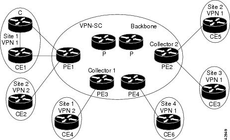
The PE routers export the captured flows to the configured collector devices in the provider network. Applications such as the Network Data Analyzer or the VPN Solution Center (VPN-SC) can gather information from the captured flows and compute and display site-to-site VPN traffic statistics.
How to Configure MPLS Egress NetFlow Accounting
•![]() Configuring MPLS Egress NetFlow Accounting (required)
Configuring MPLS Egress NetFlow Accounting (required)
•![]() Verifying MPLS Egress NetFlow Accounting Configuration (optional)
Verifying MPLS Egress NetFlow Accounting Configuration (optional)
Configuring MPLS Egress NetFlow Accounting
Perform the steps in this required task to configure MPLS egress NetFlow accounting.
SUMMARY STEPS
1. ![]() enable
enable
2. ![]() configure terminal
configure terminal
3. ![]() interface interface-type interface-number
interface interface-type interface-number
4. ![]() mpls netflow egress
mpls netflow egress
5. ![]() end
end
DETAILED STEPS
Troubleshooting Tips
To display debug messages for MPLS egress NetFlow accounting, use the debug mpls netflow command.
Verifying MPLS Egress NetFlow Accounting Configuration
Perform the steps in this optional task to verify that the MPLS Egress NetFlow Accounting configuration is as you expect.
SUMMARY STEPS
1. ![]() show ip cache flow
show ip cache flow
2. ![]() show mpls forwarding-table detail
show mpls forwarding-table detail
3. ![]() show mpls interfaces internal
show mpls interfaces internal
DETAILED STEPS
Step 1 ![]() show ip cache flow
show ip cache flow
Use this command to verify that the MPLS Egress NetFlow Accounting configuration is as you expect. For example:
Router# show ip cache flow
IP packet size distribution (10 total packets):
1-32 64 96 128 160 192 224 256 288 320 352 384 416 448 480
.000 .000 .000 1.00 .000 .000 .000 .000 .000 .000 .000 .000 .000 .000 .000
512 544 576 1024 1536 2048 2560 3072 3584 4096 4608
.000 .000 .000 .000 .000 .000 .000 .000 .000 .000 .000
IP Flow Switching Cache, 4456704 bytes
1 active, 65535 inactive, 2 added
26 ager polls, 0 flow alloc failures
Active flows timeout in 30 minutes
Inactive flows timeout in 15 seconds
last clearing of statistics never
Protocol Total Flows Packets Bytes Packets Active(Sec) Idle(Sec)
-------- Flows /Sec /Flow /Pkt /Sec /Flow /Flow
ICMP 1 0.0 5 100 0.0 0.0 15.7
Total : 1 0.0 5 100 0.0 0.0 15.7
SrcIf SrcIPaddress DstIf DstIPaddress Pr SrcP DstP Pkts
Et1/1 209.165.200.225 Et1/4 209.165.201.2 01 0000 0800 5
Step 2 ![]() show mpls forwarding-table detail
show mpls forwarding-table detail
Use this command to verify the configuration of MPLS egress NetFlow accounting. Check that the quick flag is set for prefixes, which indicates capture by MPLS egress NetFlow accounting. For example:
Router# show mpls forwarding-table detail
Local Outgoing Prefix Bytes tag Outgoing Next Hop
tag tag or VC or Tunnel Id switched interface
16 Aggregate 34.0.0.0/8[V] 0
MAC/Encaps=0/0, MTU=0, Tag Stack{}
VPN route: vpn1
Feature Quick flag set

Note ![]() As shown above, the quick flag is set for the first two prefixes; therefore, traffic destined for those prefixes is captured by MPLS egress NetFlow accounting.
As shown above, the quick flag is set for the first two prefixes; therefore, traffic destined for those prefixes is captured by MPLS egress NetFlow accounting.
Per-packet load-sharing, slots: 0 1 2 3 4 5 6 7 8 9 10 11 12 13 14 15
17 Untagged 2.0.0.0/8[V] 0 Et0/0/2 34.0.0.1
MAC/Encaps=0/0, MTU=1500, Tag Stack{}
VPN route: vpn1
Feature Quick flag set
Per-packet load-sharing, slots: 0 1 2 3 4 5 6 7 8 9 10 11 12 13 14 15
18 Untagged 42.42.42.42/32[V] 4185 Et0/0/2 34.0.0.1
MAC/Encaps=0/0, MTU=1500, Tag Stack{}
VPN route: vpn1
Feature Quick flag set
Per-packet load-sharing, slots: 0 1 2 3 4 5 6 7 8 9 10 11 12 13 14 15
19 2/33 41.41.41.41/32 0 AT1/0/0.1 point2point
MAC/Encaps=4/8, MTU=4470, Tag Stack{2/33(vcd=2)}
00028847 00002000
No output feature configured
Note ![]() As shown above, the feature is not configured because MPLS egress NetFlow accounting is not enabled on the outgoing interface for this prefix.
As shown above, the feature is not configured because MPLS egress NetFlow accounting is not enabled on the outgoing interface for this prefix.
Per-packet load-sharing, slots: 0 1 2 3 4 5 6 7 8 9 10 11 12 13 14 15
20 Aggregate 39.39.39.39/32[V] 0
Local Outgoing Prefix Bytes tag Outgoing Next Hop
tag tag or VC or Tunnel Id switched interface
MAC/Encaps=0/0, MTU=0, Tag Stack{}
VPN route: vpn1
No output feature configured
Per-packet load-sharing, slots: 0 1 2 3 4 5 6 7 8 9 10 11 12 13 14 15
Router#
Step 3 ![]() show mpls interfaces internal
show mpls interfaces internal
Use this command to show whether or not MPLS egress NetFlow accounting is enabled on the interface. For example:
Router# show mpls interfaces internal
Interface Ethernet0/0/1:
IP tagging enabled (tdp)
TSP Tunnel tagging not enabled
Tag Frame Relay Transport tagging not enabled
Tagging operational
IP to Tag Fast Feature Switching Vector
Tag Switching Turbo Feature Vector
MTU = 1500, status=0x100043, appcount=1
Output_feature_state=0x0
Note ![]() The "Output_feature_state=0x0" entry indicates that MPLS egress NetFlow accounting is disabled on interface Ethernet 0/0/1.
The "Output_feature_state=0x0" entry indicates that MPLS egress NetFlow accounting is disabled on interface Ethernet 0/0/1.
Tag VPI = 1, Control VC = 0/32
Interface Ethernet0/0/2:
IP tagging enabled (tdp)
TSP Tunnel tagging not enabled
Tag Frame Relay Transport tagging not enabled
Tagging operational
IP to Tag Fast Feature Switching Vector
Tag Switching Turbo Feature Vector
MTU = 1500, status=0x100043, appcount=1
Output_feature_state=0x1
Note ![]() The "Output_feature_state=0x1" entry indicates that MPLS egress NetFlow accounting is enabled on interface Ethernet 0/0/2.
The "Output_feature_state=0x1" entry indicates that MPLS egress NetFlow accounting is enabled on interface Ethernet 0/0/2.
Tag VPI = 1, Control VC = 0/32
Interface ATM1/0/0.1:
IP tagging enabled (tdp)
Configuration Examples for Configuring MPLS Egress NetFlow Accounting
•![]() Enabling MPLS Egress NetFlow Accounting: Example
Enabling MPLS Egress NetFlow Accounting: Example
Enabling MPLS Egress NetFlow Accounting: Example
This section contains a sample configuration for the MPLS Egress NetFlow Accounting feature.
The show ip vrf command lists the Virtual Private Network (VPN) routing and forwarding instances (VRFs) configured in the router:
Router# show ip vrf
Name Default RD Interfaces
vpn1 100:1 Ethernet1/4
Loopback1
vpn3 300:1 Ethernet1/2
Loopback2
In the following example, MPLS Egress NetFlow Accounting is enabled on interface Ethernet 1/4:
configure terminal
!
interface ethernet 1/4
ip address 172.17.24.2 255.255.255.0
mpls netflow egress
exit
Enter the show running-config command to view the current configuration in the router:
Router# show running-config
Building configuration...
Current configuration:
!
version 12.0
service timestamps debug uptime
service timestamps log uptime
no service password-encryption
ip cef
no ip domain-lookup
!
This section of the output shows the VRF being defined and shows that the MPLS Egress NetFlow Accounting feature is enabled:
ip vrf vpn1
rd 100:1
route-target export 100:1
route-target import 100:1
!
interface Loopback0
ip address 10.41.41.41 255.255.255.255
no ip directed-broadcast
no ip mroute-cache
!
interface Ethernet1/4
ip vrf forwarding vpn1
ip address 172.17.24.2 255.255.255.0
no ip directed-broadcast
mpls netflow egress
!
Additional References
Related Documents
|
|
|
|---|---|
Overview of Cisco IOS NetFlow |
|
List of the features documented in the Cisco IOS NetFlow Configuration Guide configuration guide |
|
The minimum information about and tasks required for configuring NetFlow and NetFlow Data Export |
Getting Started with Configuring NetFlow and NetFlow Data Export |
Tasks for configuring NetFlow to capture and export network traffic data |
|
Tasks for configuring Configuring MPLS Aware NetFlow |
|
Tasks for configuring NetFlow input filters |
Using NetFlow Filtering or Sampling to Select the Network Traffic to Track |
Tasks for configuring Random Sampled NetFlow |
Using NetFlow Filtering or Sampling to Select the Network Traffic to Track |
Tasks for configuring NetFlow aggregation caches |
|
Tasks for configuring NetFlow BGP next hop support |
Configuring NetFlow BGP Next Hop Support for Accounting and Analysis |
Tasks for configuring NetFlow multicast support |
|
Tasks for detecting and analyzing network threats with NetFlow |
|
Tasks for configuring NetFlow Reliable Export With SCTP |
|
Tasks for configuring NetFlow Layer 2 and Security Monitoring Exports |
|
Tasks for configuring the SNMP NetFlow MIB |
Configuring SNMP and using the NetFlow MIB to Monitor NetFlow Data |
Tasks for configuring the NetFlow MIB and Top Talkers feature |
Configuring NetFlow Top Talkers using Cisco IOS CLI Commands or SNMP Commands |
Information for installing, starting, and configuring the CNS NetFlow Collection Engine |
Standards
|
|
|
|---|---|
No new or modified standards are supported by this feature, and support for existing standards has not been modified by this feature. |
— |
MIBs
RFCs
|
|
|
|---|---|
RFC 1163 |
Border Gateway Protocol (BGP) |
RFC 1340 |
Assigned Numbers |
RFC 1918 |
Address Allocation For Private Internets |
RFC 2547 |
BGP/MPLS VPNs |
Technical Assistance
Feature Information for Configuring MPLS Egress NetFlow Accounting
Table 1 lists the features in this module and provides links to specific configuration information. Only features that were introduced or modified in Cisco IOS Release 12.1(5)T or 12.0(3)S or a later release appear in the table.
Not all commands may be available in your Cisco IOS software release. For details on when support for a specific command was introduced, see the command reference documentation.
For information on a feature in this technology that is not documented here, see the Cisco IOS NetFlow Features Roadmap.
Cisco IOS software images are specific to a Cisco IOS software release, a feature set, and a platform. Use Cisco Feature Navigator to find information about platform support and Cisco IOS software image support. Access Cisco Feature Navigator at http://www.cisco.com/go/fn. You must have an account on Cisco.com. If you do not have an account or have forgotten your username or password, click Cancel at the login dialog box and follow the instructions that appear.
Note ![]() Table 1 lists only the Cisco IOS software release that introduced support for a given feature in a given Cisco IOS software release train. Unless noted otherwise, subsequent releases of that Cisco IOS software release train also support that feature.
Table 1 lists only the Cisco IOS software release that introduced support for a given feature in a given Cisco IOS software release train. Unless noted otherwise, subsequent releases of that Cisco IOS software release train also support that feature.
|
|
|
|
|---|---|---|
MPLS Egress NetFlow Accounting |
12.1(5)T |
The MPLS Egress NetFlow Accounting feature allows you to capture IP flow information for packets that are undergoing MPLS label disposition; that is, packets that arrive on a router as MPLS packets and that are transmitted as IP packets. The following sections provide information about this feature: • • • • The following commands were introduced or modified by this feature: debug mpls netflow, mpls netflow egress, show mpls forwarding-table, and show mpls interface. |
Glossary
BGP—Border Gateway Protocol. An interdomain routing protocol that replaces Exterior Gateway Protocol (EGP). A BGP system exchanges reachability information with other BGP systems. BGP is defined by RFC 1163.
BGP/MPLS/VPN—A Virtual Private Network (VPN) solution that uses Multiprotocol Label Switching (MPLS) and Border Gateway Protocol (BGP) to allow multiple remote customer sites to be connected over an IP backbone. Refer to RFC 2547 for details.
CE router—A customer edge router. A router that is part of a customer network and interfaces to a provider edge (PE) router.
customer network—A network that is under the control of an end customer. A customer network can use private addresses as defined in RFC 1918. Customer networks are logically isolated from each other and from the provider network. A customer network is also known as a C network.
egress PE—The provider edge router through which traffic moves from the backbone to the destination Virtual Private Network (VPN) site.
flow—A set of packets with the same source IP address, destination IP address, source/destination ports, and type-of-service, and the same interface on which flow is monitored. Ingress flows are associated with the input interface, and egress flows are associated with the output interface.
ingress PE—The provider edge router through which traffic enters the backbone (provider network) from a Virtual Private Network (VPN) site.
label—A short, fixed length identifier that tells switching nodes how the data (packets or cells) should be forwarded.
MPLS—Multiprotocol Label Switching. An emerging industry standard for the forwarding of packets along normally routed paths (sometimes called MPLS hop-by-hop forwarding).
PE router—A provider edge router. A router at the edge of a provider network that interfaces to customer edge (CE) routers.
provider network—A backbone network that is under the control of a service provider and provides transport among customer sites. A provider network is also known as the P network.
VPN—Virtual Private Network. The result of a router configuration that enables IP traffic to use tunneling to travel securely over a public TCP/IP network.
VRF—Virtual Private Network (VPN) routing/forwarding instance. The VRF is a key element in the MPLS VPN technology. VRFs exist on PEs only. A VRF is populated with VPN routes and allows one PE to have multiple routing tables. One VRF is required per VPN on each PE in the VPN.
 Feedback