- BGP Features Roadmap
- Cisco BGP Overview
- Configuring a Basic BGP Network
- Connecting to a Service Provider Using External BGP
- Removing Private AS Numbers from the AS Path in BGP
- Configuring BGP Neighbor Session Options
- Configuring Internal BGP Features
- Configuring Advanced BGP Features
- Configuring Multiprotocol BGP (MP-BGP) Support for CLNS
- BGP Link Bandwidth
- iBGP Multipath Load Sharing
- BGP Multipath Load Sharing for Both eBGP and iBGP in an MPLS-VPN
- Loadsharing IP Packets Over More Than Six Parallel Paths
- BGP Policy Accounting
- BGP Cost Community
- BGP Support for IP Prefix Import from Global Table into a VRF Table
- BGP per Neighbor SoO Configuration
- BGP Next Hop Unchanged
- Per-VRF Assignment of BGP Router ID
- BGP Support for the L2VPN Address Family
- BGP 4 MIB Support for per-Peer Received Routes
- Detecting and Mitigating a BGP Slow Peer
- BGP Support for Nonstop Routing (NSR) with Stateful Switchover (SSO)
- BGP: RT Constrained Route Distribution
IP Routing: BGP Configuration Guide, Cisco IOS Release 15.1S
Bias-Free Language
The documentation set for this product strives to use bias-free language. For the purposes of this documentation set, bias-free is defined as language that does not imply discrimination based on age, disability, gender, racial identity, ethnic identity, sexual orientation, socioeconomic status, and intersectionality. Exceptions may be present in the documentation due to language that is hardcoded in the user interfaces of the product software, language used based on RFP documentation, or language that is used by a referenced third-party product. Learn more about how Cisco is using Inclusive Language.
- Updated:
- December 20, 2010
Chapter: BGP: RT Constrained Route Distribution
- Finding Feature Information
- Contents
- Prerequisites for BGP: RT Constrained Route Distribution
- Restrictions for BGP: RT Constrained Route Distribution
- Information About BGP: RT Constrained Route Distribution
- How to Configure RT Constrained Route Distribution
- Configuration Examples for BGP: RT Constrained Route Distribution
- Additional References
- Feature Information for BGP: RT Constrained Route Distribution
Configuring BGP: RT Constrained Route Distribution
BGP: RT Constrained Route Distribution is a feature that service providers can use in Multiprotocol Label Switching (MPLS) Layer 3 Virtual Private Networks (L3VPNs) to reduce the number of unnecessary routing updates that route reflectors (RRs) send to PEs. The reduction in routing updates saves resources. RRs, autonomous system boundary routers (ASBRs), and PEs will have fewer routes to carry. Route targets are used to constrain routing updates.
Finding Feature Information
Your software release may not support all the features documented in this module. For the latest feature information and caveats, see the release notes for your platform and software release. To find information about the features documented in this module, and to see a list of the releases in which each feature is supported, see the "Feature Information for BGP: RT Constrained Route Distribution" section.
Use Cisco Feature Navigator to find information about platform support and software image support. To access Cisco Feature Navigator, go to http://www.cisco.com/go/cfn. An account on Cisco.com is not required.
Contents
•![]() Prerequisites for BGP: RT Constrained Route Distribution
Prerequisites for BGP: RT Constrained Route Distribution
•![]() Restrictions for BGP: RT Constrained Route Distribution
Restrictions for BGP: RT Constrained Route Distribution
•![]() Information About BGP: RT Constrained Route Distribution
Information About BGP: RT Constrained Route Distribution
•![]() How to Configure RT Constrained Route Distribution
How to Configure RT Constrained Route Distribution
•![]() Configuration Examples for BGP: RT Constrained Route Distribution
Configuration Examples for BGP: RT Constrained Route Distribution
•![]() Feature Information for BGP: RT Constrained Route Distribution
Feature Information for BGP: RT Constrained Route Distribution
Prerequisites for BGP: RT Constrained Route Distribution
Before you configure BGP: RT Constrained Route Distribution, you should understand how to configure the following:
•![]() MPLS VPNs
MPLS VPNs
•![]() Route distinguishers (RDs)
Route distinguishers (RDs)
•![]() Route targets (RTs)
Route targets (RTs)
•![]() Multiprotocol BGP (MBGP)
Multiprotocol BGP (MBGP)
Restrictions for BGP: RT Constrained Route Distribution
BGP: RT Constrained Route Distribution constrains VPNv4 and VPNv6 route advertisements only.
Information About BGP: RT Constrained Route Distribution
•![]() Problem that BGP: RT Constrained Route Distribution Solves
Problem that BGP: RT Constrained Route Distribution Solves
•![]() Benefits of BGP: RT Constrained Route Distribution
Benefits of BGP: RT Constrained Route Distribution
•![]() How BGP: RT Constrained Route Distribution Works
How BGP: RT Constrained Route Distribution Works
•![]() Example of RT Constrained Route Distribution Process
Example of RT Constrained Route Distribution Process
Problem that BGP: RT Constrained Route Distribution Solves
Some service providers have a very large number of routing updates being sent from RRs to PEs, using considerable resources. A PE does not need routing updates for VRFs that are not on the PE; therefore, the PE determines that many routing updates it receives are "unwanted." The PE filters out the unwanted updates.
Figure 1 illustrates a scenario in which unwanted routing updates arrive at two PEs.
Figure 1 Unwanted Routing Updates at PE
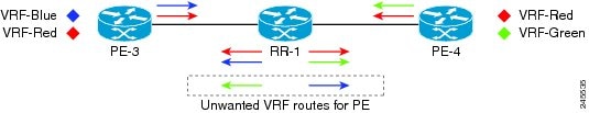
As shown in Figure 1, a PE receives unwanted routes in the following manner:
1. ![]() PE-3 advertises VRF Blue and VRF Red routes to RR-1. PE-4 advertises VRF Red and VRF Green routes to RR-1.
PE-3 advertises VRF Blue and VRF Red routes to RR-1. PE-4 advertises VRF Red and VRF Green routes to RR-1.
2. ![]() RR-1 has all of the routes for all of the VRFs (Blue, Red, and Green).
RR-1 has all of the routes for all of the VRFs (Blue, Red, and Green).
3. ![]() During a route refresh or VRF provisioning, RR-1 advertises all of the VRF routes to both PE-3 and PE-4.
During a route refresh or VRF provisioning, RR-1 advertises all of the VRF routes to both PE-3 and PE-4.
4. ![]() Routes for VRF Green are unwanted at PE-3. Routes for VRF Blue are unwanted at PE-4.
Routes for VRF Green are unwanted at PE-3. Routes for VRF Blue are unwanted at PE-4.
Now consider the scenario where there are two RRs with another set of PEs. Not only are there unwanted routing updates from RR to PE, there are also unwanted routing updates between RRs. Figure 2 illustrates a scenario in which unwanted routes arrive at a RR.
Figure 2 Unwanted Routing Updates at RR
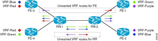
As shown in Figure 2, RR-1 and RR-2 receive unwanted routing updates in the following manner:
1. ![]() PE-3 and PE-4 advertise VRF Blue, VRF Red, and VRF Green VPN routes to RR-1.
PE-3 and PE-4 advertise VRF Blue, VRF Red, and VRF Green VPN routes to RR-1.
2. ![]() RR-1 sends all of its VPN routes to RR-2.
RR-1 sends all of its VPN routes to RR-2.
3. ![]() VRF Red routes are unwanted on RR-2 because PE-1 and PE-2 do not have VRF Red.
VRF Red routes are unwanted on RR-2 because PE-1 and PE-2 do not have VRF Red.
4. ![]() Similarly, VRF Purple routes are unwanted on RR-1 because PE-3 and PE-4 do not have VRF Purple.
Similarly, VRF Purple routes are unwanted on RR-1 because PE-3 and PE-4 do not have VRF Purple.
Hence, a large number of unwanted routes might be advertised among RRs and PEs. The BGP: RT Constrained Route Distribution feature addresses this problem by filtering unwanted routing updates.
Before the BGP: RT Constrained Route Distribution feature, the PE would filter the updates. With this feature, the burden is moved to the RR to filter the updates.
Benefits of BGP: RT Constrained Route Distribution
In MPLS L3VPNs, PE routers use BGP and Route Target (RT) extended communities to control the distribution of VPN routes to and from VRFs in order to separate the VPNs. It is common for PEs and Autonomous System Boundary Routers (ASBRs) to receive and then filter out the unwanted VPN routes.
However, receiving and filtering unwanted VPN routes is a waste of resources. The sender generates and transmits a VPN routing update and the receiver filters out the unwanted routes. It would save resources to prevent the generation of such VPN route updates in the first place.
ARTF is a mechanism that prevents the propagation of VPN Network Layer Reachability Information (NLRI) from the RR to a PE that is not interested in the VPN. The feature provides considerable savings in CPU cycles and transient memory usage. RT constraint limits the number of VPN routes and describes VPN membership.
BGP RT-Constrain SAFI
The BGP: RT Constrained Route Distribution feature introduces a new Subsequent Address Family Identifier (SAFI), the BGP RT-Constrain SAFI. The command to enter that address family is the address-family rtfilter unicast command.
How BGP: RT Constrained Route Distribution Works
In order to filter out the unwanted routes described in the "Problem that BGP: RT Constrained Route Distribution Solves" section, the PEs and RRs must be configured with the BGP: RT Constrained Route Distribution feature.
The feature allows the PE to propagate RT membership and use the RT membership to limit the VPN routing information maintained at the PE and RR. The PE uses an MP-BGP UPDATE message to propagate the membership information. The RR restricts advertisement of VPN routes based on the RT membership information it received.
This feature causes two exchanges to happen:
•![]() The PE sends RT Constraint network layer reachability information (NLRI) to the RR.
The PE sends RT Constraint network layer reachability information (NLRI) to the RR.
•![]() The RR installs an outbound route filter.
The RR installs an outbound route filter.
Figure 3 illustrates the exchange of the RT Constraint (RTC) NLRI and the outbound route filter.
Figure 3 Exchange of RTC NLRI and Filter Between PE and RR
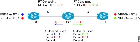
As shown in Figure 3, the following exchange occurs between the PE and the RR:
1. ![]() PE-3 sends RTC NLRI {RT 1, RT 2} to RR-1.
PE-3 sends RTC NLRI {RT 1, RT 2} to RR-1.
2. ![]() PE-4 sends RTC NLRI {RT 2, RT 3} to RR-1.
PE-4 sends RTC NLRI {RT 2, RT 3} to RR-1.
3. ![]() RR-1 translates the NLRI into an outbound route filter and installs this filter (Permit RT 1, RT 2) for PE-3.
RR-1 translates the NLRI into an outbound route filter and installs this filter (Permit RT 1, RT 2) for PE-3.
4. ![]() RR-1 translates the NLRI into an outbound route filter and installs this filter (Permit RT 2, RT 3) for PE-4.
RR-1 translates the NLRI into an outbound route filter and installs this filter (Permit RT 2, RT 3) for PE-4.
RT Constraint NLRI Prefix
The format of the RT Constraint NLRI is a prefix that is always 12 bytes long, consisting of the following:
•![]() 4-byte origin autonomous system
4-byte origin autonomous system
•![]() 8-byte RT extended community value
8-byte RT extended community value
The following are examples of RT Constraint prefixes
•![]() 65000:2:100:1
65000:2:100:1
–![]() Origin autonomous system number is 65000
Origin autonomous system number is 65000
–![]() BGP Extended Community Type Code is 2
BGP Extended Community Type Code is 2
–![]() Route Target is 100:1
Route Target is 100:1
•![]() 65001:256:192.0.0.1:100
65001:256:192.0.0.1:100
–![]() Origin ASN is 65001
Origin ASN is 65001
–![]() BGP Extended Community Type Code is 256
BGP Extended Community Type Code is 256
–![]() Route Target is 192.0.0.1:100
Route Target is 192.0.0.1:100
•![]() 1.10:512:1.10:2
1.10:512:1.10:2
–![]() Origin ASN is 4-byte, unique 1.10
Origin ASN is 4-byte, unique 1.10
–![]() BGP Extended Community Type Code is 512
BGP Extended Community Type Code is 512
–![]() Route Target is 1.10:2
Route Target is 1.10:2
To determine what the BGP Extended Community Type Code means, refer to RFC 4360, BGP Extended Communities Attribute. In the first example above, a 2 translates in hexadecimal to 0x002. In RFC 4360, 0x002 indicates that the value that follows the Type Code will be a two-octet AS specific Route Target.
Example of RT Constrained Route Distribution Process
To illustrate the RT Constrained Route Distribution process, this example has two CE routers in AS 100 that are connected to PE1. PE1 communicates with PE2, which is also connected to CE routers. Between the two PEs is a route reflector (RR). PE1 and PE2 belong to AS 65000.
The general process for the feature is as follows:
1. ![]() The user configures PE1 to activate its BGP peers under the address-family rtfilter unicast command.
The user configures PE1 to activate its BGP peers under the address-family rtfilter unicast command.
2. ![]() The user configures PE1 in AS 65000 with route-target import 100:1, for example.
The user configures PE1 in AS 65000 with route-target import 100:1, for example.
3. ![]() PE1 translates that command to an RT prefix of 65000:2:100:1. The 65000 is the service provider's AS number; the 2 is the BGP Extended Communities Type Code; and the 100:1 is the CE's RT (AS number and another number).
PE1 translates that command to an RT prefix of 65000:2:100:1. The 65000 is the service provider's AS number; the 2 is the BGP Extended Communities Type Code; and the 100:1 is the CE's RT (AS number and another number).
4. ![]() PE1 advertises the RT Constrain (RTC) prefix of 65000:2:100:1 to its iBGP peer RR.
PE1 advertises the RT Constrain (RTC) prefix of 65000:2:100:1 to its iBGP peer RR.
5. ![]() The RR installs RTC 65000:2:100:1 into the RTC RIB. Each VRF has its own RIB.
The RR installs RTC 65000:2:100:1 into the RTC RIB. Each VRF has its own RIB.
6. ![]() The RR also installs RTC 65000:2:100:1 into its outbound filter for the neighbor PE2.
The RR also installs RTC 65000:2:100:1 into its outbound filter for the neighbor PE2.
7. ![]() The RR has a filter that either permits or denies the RT. (The AS number is ignored because iBGP is operating in a single AS and does not need to track the AS number.)
The RR has a filter that either permits or denies the RT. (The AS number is ignored because iBGP is operating in a single AS and does not need to track the AS number.)
8. ![]() PE1 sends an update packet to RR. RR looks in its filter and sees that it will permit outbound packets
PE1 sends an update packet to RR. RR looks in its filter and sees that it will permit outbound packets
Default RT Filter
The default RT filter has a value of zero and length of zero. The default RT filter is used:
•![]() By a peer to indicate that the peer wants all of the VPN routes sent to it, regardless of the RT value.
By a peer to indicate that the peer wants all of the VPN routes sent to it, regardless of the RT value.
•![]() By the RR to request that the PE advertise all of its VPN routes to the RR.
By the RR to request that the PE advertise all of its VPN routes to the RR.
The default RT filter is created by configuring the neighbor default-originate command under the address-family rtfilter unicast command.
How to Configure RT Constrained Route Distribution
Perform these tasks to configure BGP: RT Constrained Route Distribution. The first three tasks are typical for an MPLS environment. The last task enables the exchange of Automated RT Filter information with the specified BGP neighbor.
•![]() Configuring Multiprotocol BGP on the PE Routers and Route Reflectors (required)
Configuring Multiprotocol BGP on the PE Routers and Route Reflectors (required)
•![]() Connecting the MPLS VPN Customers (required)
Connecting the MPLS VPN Customers (required)
•![]() Configuring RT Constraint on the PE (required)
Configuring RT Constraint on the PE (required)
•![]() Configuring RT Constraint on the RR (required)
Configuring RT Constraint on the RR (required)
Configuring Multiprotocol BGP on the PE Routers and Route Reflectors
Perform this task to configure multiprotocol BGP (MP-BGP) connectivity on the PE routers and route reflectors.
SUMMARY STEPS
1. ![]() enable
enable
2. ![]() configure terminal
configure terminal
3. ![]() router bgp as-number
router bgp as-number
4. ![]() no bgp default ipv4-unicast
no bgp default ipv4-unicast
5. ![]() neighbor {ip-address | peer-group-name} remote-as as-number
neighbor {ip-address | peer-group-name} remote-as as-number
6. ![]() neighbor {ip-address | peer-group-name} activate
neighbor {ip-address | peer-group-name} activate
7. ![]() address-family vpnv4 [unicast]
address-family vpnv4 [unicast]
8. ![]() neighbor {ip-address | peer-group-name} send-community extended
neighbor {ip-address | peer-group-name} send-community extended
9. ![]() neighbor {ip-address | peer-group-name} activate
neighbor {ip-address | peer-group-name} activate
10. ![]() end
end
DETAILED STEPS
Troubleshooting Tips
You can enter a show ip bgp neighbor command to verify that the neighbors are up and running. If this command is not successful, enter a debug ip bgp x.x.x.x events command, where x.x.x.x is the IP address of the neighbor.
Connecting the MPLS VPN Customers
To connect the MPLS VPN customers to the VPN, perform the following tasks:
•![]() Defining VRFs on the PE Routers to Enable Customer Connectivity (required)
Defining VRFs on the PE Routers to Enable Customer Connectivity (required)
•![]() Configuring VRF Interfaces on PE Routers for Each VPN Customer (required)
Configuring VRF Interfaces on PE Routers for Each VPN Customer (required)
•![]() Configuring BGP as the Routing Protocol Between the PE and CE Routers (required)
Configuring BGP as the Routing Protocol Between the PE and CE Routers (required)
Defining VRFs on the PE Routers to Enable Customer Connectivity
To define virtual routing and forwarding (VRF) instances, perform this task.
SUMMARY STEPS
1. ![]() enable
enable
2. ![]() configure terminal
configure terminal
3. ![]() ip vrf vrf-name
ip vrf vrf-name
4. ![]() rd route-distinguisher
rd route-distinguisher
5. ![]() route-target {import | export | both} route-target-ext-community
route-target {import | export | both} route-target-ext-community
6. ![]() import map route-map
import map route-map
7. ![]() exit
exit
DETAILED STEPS
Configuring VRF Interfaces on PE Routers for Each VPN Customer
To associate a VRF with an interface or subinterface on the PE routers, perform this task.
SUMMARY STEPS
1. ![]() enable
enable
2. ![]() configure terminal
configure terminal
3. ![]() interface type number
interface type number
4. ![]() ip vrf forwarding vrf-name
ip vrf forwarding vrf-name
5. ![]() end
end
DETAILED STEPS
Configuring BGP as the Routing Protocol Between the PE and CE Routers
To configure PE-to-CE routing sessions using BGP, perform this task.
SUMMARY STEPS
1. ![]() enable
enable
2. ![]() configure terminal
configure terminal
3. ![]() router bgp as-number
router bgp as-number
4. ![]() address-family ipv4 [multicast | unicast | vrf vrf-name]
address-family ipv4 [multicast | unicast | vrf vrf-name]
5. ![]() neighbor {ip-address | peer-group-name} remote-as as-number
neighbor {ip-address | peer-group-name} remote-as as-number
6. ![]() neighbor {ip-address | peer-group-name} activate
neighbor {ip-address | peer-group-name} activate
7. ![]() exit-address-family
exit-address-family
8. ![]() end
end
DETAILED STEPS
Configuring RT Constraint on the PE
Perform this task on the PE to configure BGP: RT Constrained Route Distribution with the specified neighbor, and optionally verify that route target (RT) filtering is occurring.
SUMMARY STEPS
1. ![]() enable
enable
2. ![]() configure terminal
configure terminal
3. ![]() router bgp as-number
router bgp as-number
4. ![]() address-family rtfilter unicast
address-family rtfilter unicast
5. ![]() neighbor {ip-address | peer-group-name} activate
neighbor {ip-address | peer-group-name} activate
6. ![]() end
end
7. ![]() show ip bgp rtfilter all
show ip bgp rtfilter all
8. ![]() show ip bgp rtfilter all summary
show ip bgp rtfilter all summary
9. ![]() show ip bgp vpnv4 all
show ip bgp vpnv4 all
DETAILED STEPS
Configuring RT Constraint on the RR
Perform this task on the RR to configure BGP: RT Constrained Route Distribution with the specified neighbor, and optionally verify that route target (RT) filtering is occurring.
SUMMARY STEPS
1. ![]() enable
enable
2. ![]() configure terminal
configure terminal
3. ![]() router bgp as-number
router bgp as-number
4. ![]() address-family rtfilter unicast
address-family rtfilter unicast
5. ![]() neighbor {ip-address | peer-group-name} send-community extended
neighbor {ip-address | peer-group-name} send-community extended
6. ![]() neighbor {ip-address | peer-group-name} activate
neighbor {ip-address | peer-group-name} activate
7. ![]() neighbor {ip-address | peer-group-name} route-reflector-client
neighbor {ip-address | peer-group-name} route-reflector-client
8. ![]() end
end
9. ![]() show ip bgp rtfilter all
show ip bgp rtfilter all
10. ![]() show ip bgp rtfilter all summary
show ip bgp rtfilter all summary
11. ![]() show ip bgp vpnv4 all
show ip bgp vpnv4 all
DETAILED STEPS
|
|
|
|
|---|---|---|
Step 1 |
enable Router> enable |
Enables privileged EXEC mode. • |
Step 2 |
configure terminal Router# configure terminal |
Enters global configuration mode. |
Step 3 |
router bgp as-number Router(config)# router bgp 1 |
Configures a BGP routing process and enters router configuration mode. |
Step 4 |
address-family rtfilter unicast Router(config-router)# address-family rtfilter unicast |
Specifies the RT filter address family type and enters address family configuration mode. |
Step 5 |
neighbor Router(config-router-af)# |
Specifies that a communities attribute should be sent to a BGP neighbor. • • |
Step 6 |
neighbor {ip-address | peer-group-name} activate Router(config-router-af)# |
Enables RT Constraint with the specified BGP neighbor. |
Step 7 |
neighbor {ip-address | peer-group-name} route-reflector-client Router(config-router-af)# |
Enables RT Constraint with the specified BGP neighbor. • |
Step 8 |
end Router(config-router-af)# |
Exits configuration mode and returns to privileged EXEC mode. |
Step 9 |
show ip bgp rtfilter all Router# |
(Optional) Displays all BGP RT filter information. |
Step 10 |
show ip bgp rtfilter all summary Router# |
(Optional) Displays summary BGP RT filter information. |
Step 11 |
show ip bgp vpnv4 all Router# |
(Optional) Displays summary BGP VPNv4 information. |
Configuration Examples for BGP: RT Constrained Route Distribution
•![]() Example: BGP: RT Constrained Route Distribution Between a PE and RR
Example: BGP: RT Constrained Route Distribution Between a PE and RR
Example: BGP: RT Constrained Route Distribution Between a PE and RR
In the following example provides the configurations of the routers in Figure 4. PE1 and PE2 are each connected to the RR and belong to AS 65000.
Figure 4 BGP: RT Constrained Route Distribution Between a PE and RR
PE1 Configuration
ip vrf BLUE
rd 3:3
route-target export 1:100
route-target import 1:100
!
router bgp 65000
bgp log-neighbor-changes
neighbor 192.168.2.2 remote-as 1
neighbor 192.168.2.2 update-source Loopback0
no auto-summary
!
address-family vpnv4
neighbor 192.168.2.2 activate
neighbor 192.168.2.2 send-community extended
exit-address-family
!
address-family rtfilter unicast
neighbor 192.168.2.2 activate
neighbor 192.168.2.2 send-community extended
exit-address-family
!
address-family ipv4 vrf BLUE
redistribute static
exit-address-family
!
ip route vrf BLUE 51.51.51.51 255.255.255.255 Null0
!
RR Configuration
!
router bgp 65000
bgp log-neighbor-changes
bgp graceful-restart restart-time 120
bgp graceful-restart stalepath-time 360
bgp graceful-restart
neighbor 192.168.6.6 remote-as 1
neighbor 192.168.6.6 update-source Loopback0
neighbor 192.168.7.7 remote-as 1
neighbor 192.168.7.7 update-source Loopback0
!
address-family vpnv4
neighbor 192.168.6.6 activate
neighbor 192.168.6.6 send-community extended
neighbor 192.168.6.6 route-reflector-client
neighbor 192.168.7.7 activate
neighbor 192.168.7.7 send-community extended
neighbor 192.168.7.7 route-reflector-client
exit-address-family
!
address-family rtfilter unicast
neighbor 192.168.6.6 activate
neighbor 192.168.6.6 send-community extended
neighbor 192.168.6.6 route-reflector-client
neighbor 192.168.7.7 activate
neighbor 192.168.7.7 send-community extended
neighbor 192.168.7.7 route-reflector-client
exit-address-family
!
PE2 Configuration
!
ip vrf RED
rd 17:17
route-target export 150:15
route-target import 150:1
route-target import 1:100
!
router bgp 65000
bgp log-neighbor-changes
bgp graceful-restart restart-time 120
bgp graceful-restart stalepath-time 360
bgp graceful-restart
neighbor 192.168.2.2 remote-as 1
neighbor 192.168.2.2 update-source Loopback0
neighbor 192.168.2.2 weight 333
no auto-summary
!
address-family vpnv4
neighbor 192.168.2.2 activate
neighbor 192.168.2.2 send-community extended
exit-address-family
!
address-family rtfilter unicast
neighbor 192.168.2.2 activate
neighbor 192.168.2.2 send-community extended
exit-address-family
!
Additional References
Related Documents
|
|
|
|---|---|
Cisco IOS commands |
|
BGP commands |
|
L3VPNs and route targets |
"Configuring MPLS Layer 3 VPNs" in the Cisco IOS MPLS Configuration Guide |
MPLS commands |
MIBs
|
|
|
|---|---|
— |
To locate and download MIBs for selected platforms, Cisco software releases, and feature sets, use Cisco MIB Locator found at the following URL: |
RFCs
Technical Assistance
Feature Information for BGP: RT Constrained Route Distribution
Table 1 lists the release history for this feature.
Use Cisco Feature Navigator to find information about platform support and software image support. Cisco Feature Navigator enables you to determine which software images support a specific software release, feature set, or platform. To access Cisco Feature Navigator, go to http://www.cisco.com/go/cfn. An account on Cisco.com is not required.

Note ![]() Table 1 lists only the software release that introduced support for a given feature in a given software release train. Unless noted otherwise, subsequent releases of that software release train also support that feature.
Table 1 lists only the software release that introduced support for a given feature in a given software release train. Unless noted otherwise, subsequent releases of that software release train also support that feature.
 Feedback