Wide-Area Networking Configuration Guide: Multilink PPP, Cisco IOS XE Release 3S
Bias-Free Language
The documentation set for this product strives to use bias-free language. For the purposes of this documentation set, bias-free is defined as language that does not imply discrimination based on age, disability, gender, racial identity, ethnic identity, sexual orientation, socioeconomic status, and intersectionality. Exceptions may be present in the documentation due to language that is hardcoded in the user interfaces of the product software, language used based on RFP documentation, or language that is used by a referenced third-party product. Learn more about how Cisco is using Inclusive Language.
- Updated:
- October 8, 2009
Chapter: Configuring Media-Independent PPP and Multilink PPP
- Finding Feature Information
- Contents
- Information About Media-Independent PPP and Multilink PPP
- How to Configure Media-Independent PPP and Multilink PPP
- Enabling PPP Encapsulation
- Enabling CHAP or PAP Authentication
- Enabling Link Quality Monitoring
- Configuring Compression of PPP Data
- Configuring Microsoft Point-to-Point Compression
- Configuring IP Address Pooling
- Configuring PPP Reliable Link
- Disabling or Reenabling Peer Neighbor Routes
- Configuring PPP Half-Bridging
- Configuring Multilink PPP
- Configuring MLP Interleaving and Queueing
- Monitoring and Maintaining PPP and MLP Interfaces
- Configuration Examples for PPP and MLP
- Additional References
- Feature Information for Media-Independent PPP and Multilink PPP
Configuring Media-Independent PPP and Multilink PPP
This module describes how to configure the PPP and Multilink PPP (MLP) features that can be configured on any interface.
Finding Feature Information
For the latest feature information and caveats, see the release notes for your platform and software release. To find information about the features documented in this module, and to see a list of the releases in which each feature is supported, see the Feature Information for Media-Independent PPP and Multilink PPP.
Use Cisco Feature Navigator to find information about platform support and Cisco IOS XE software image support. To access Cisco Feature Navigator, go to http://tools.cisco.com/ITDIT/CFN/jsp/index.jsp. An account on Cisco.com is not required.
Contents
•![]() Information About Media-Independent PPP and Multilink PPP
Information About Media-Independent PPP and Multilink PPP
•![]() How to Configure Media-Independent PPP and Multilink PPP
How to Configure Media-Independent PPP and Multilink PPP
•![]() Configuration Examples for PPP and MLP
Configuration Examples for PPP and MLP
•![]() Feature Information for Media-Independent PPP and Multilink PPP
Feature Information for Media-Independent PPP and Multilink PPP
Information About Media-Independent PPP and Multilink PPP
•![]() Multilink PPP Minimum Links Mandatory
Multilink PPP Minimum Links Mandatory
PPP Encapsulation Overview
PPP, described in RFC 1661, encapsulates network layer protocol information over point-to-point links. You can configure PPP on the following types of physical interfaces:
•![]() Asynchronous serial
Asynchronous serial
•![]() High-Speed Serial Interface (HSSI)
High-Speed Serial Interface (HSSI)
•![]() Synchronous serial
Synchronous serial
Challenge Handshake Authentication Protocol (CHAP) or Password Authentication Protocol (PAP)Magic Number support is available on all serial interfaces. PPP always attempts to negotiate for Magic Numbers, which are used to detect looped-back lines. Depending on how the down-when-looped command is configured, the router might shut down a link if it detects a loop.
Multilink PPP
The Multilink PPP feature provides load balancing functionality over multiple WAN links while providing multivendor interoperability, packet fragmentation, proper sequencing, and load calculation on both inbound and outbound traffic. The Cisco implementation of MLP supports the fragmentation and packet sequencing specifications in RFC 1990. Additionally, you can change the default endpoint discriminator value that is supplied as part of user authentication. Refer to RFC 1990 for more information about the endpoint discriminator.
MLP allows packets to be fragmented and the fragments to be sent at the same time over multiple point-to-point links to the same remote address. The multiple links come up in response to a defined dialer load threshold. The load can be calculated on inbound traffic, outbound traffic, or on either, as needed for the traffic between the specific sites. MLP provides bandwidth on demand and reduces transmission latency across WAN links.
MLP is designed to work over synchronous and asynchronous serial types of single or multiple interfaces that have been configured to support both dial-on-demand rotary groups and PPP encapsulation.
Multilink PPP Minimum Links Mandatory
Multilink PPP allows multiple PPP links to be established in parallel to the same destination. Multilink PPP is often used to increase the amount of bandwidth between points. The Multilink PPP Minimum Links Mandatory feature enables you to configure the minimum number of links in a Multilink PPP (MLP) bundle required to keep that bundle active.
The Multilink PPP Minimum Links Mandatory feature causes all Network Control Protocols (NCPs) for an MLP bundle to be disabled until the MLP bundle has the required minimum number of links. When a new link is added to the MLP bundle that brings the number of links up to the required minimum number of links, the NCPs are activated for the MLP bundle. When a link is removed from an MLP bundle, and the number of links falls below the required minimum number of links for that MLP bundle, the NCPs are disabled for that MLP bundle.
CHAP or PAP Authentication
PPP with CHAP or PAP authentication is often used to inform the central site about which remote routers are connected to it.
With this authentication information, if the router or access server receives another packet for a destination to which it is already connected, it does not place an additional call. However, if the router or access server is using rotaries, it sends the packet out the correct port.
CHAP and PAP were originally specified in RFC 1334, and CHAP is updated in RFC 1994. These protocols are supported on synchronous and asynchronous serial interfaces. When using CHAP or PAP authentication, each router or access server identifies itself by a name. This identification process prevents a router from placing another call to a router to which it is already connected, and also prevents unauthorized access.
Access control using CHAP or PAP is available on all serial interfaces that use PPP encapsulation. The authentication feature reduces the risk of security violations on your router or access server. You can configure either CHAP or PAP for the interface.

Note ![]() To use CHAP or PAP, you must be running PPP encapsulation.
To use CHAP or PAP, you must be running PPP encapsulation.
When CHAP is enabled on an interface and a remote device attempts to connect to it, the local router or access server sends a CHAP packet to the remote device. The CHAP packet requests or "challenges" the remote device to respond. The challenge packet consists of an ID, a random number, and the host name of the local router.
The required response has two parts:
•![]() An encrypted version of the ID, a secret password, and the random number
An encrypted version of the ID, a secret password, and the random number
•![]() Either the host name of the remote device or the name of the user on the remote device
Either the host name of the remote device or the name of the user on the remote device
When the local router or access server receives the response, it verifies the secret password by performing the same encryption operation as indicated in the response and looking up the required host name or username. The secret passwords must be identical on the remote device and the local router.
Because this response is sent, the password is never sent in clear text, preventing other devices from stealing it and gaining illegal access to the system. Without the proper response, the remote device cannot connect to the local router.
CHAP transactions occur only when a link is established. The local router or access server does not request a password during the rest of the call. (The local device can, however, respond to such requests from other devices during a call.)
When PAP is enabled, the remote router attempting to connect to the local router or access server is required to send an authentication request. If the username and password specified in the authentication request are accepted, the Cisco IOS or Cisco IOS XE software sends an authentication acknowledgment.
After you have enabled CHAP or PAP, the local router or access server requires authentication from remote devices. If the remote device does not support the enabled protocol, no traffic will be passed to that device.
Microsoft Point-to-Point Compression
Microsoft Point-to-Point Compression (MPPC) is a scheme used to compress PPP packets between Cisco and Microsoft client devices. The MPPC algorithm is designed to optimize bandwidth utilization in order to support multiple simultaneous connections. The MPPC algorithm uses a Lempel-Ziv (LZ)-based algorithm with a continuous history buffer called a dictionary.
The Compression Control Protocol (CCP) configuration option for MPPC is 18.
Exactly one MPPC datagram is encapsulated in the PPP information field. The PPP protocol field indicates the hexadecimal type of 00FD for all compressed datagrams. The maximum length of the MPPC datagram sent over PPP is the same as the MTU of the PPP interface; however, this length cannot be greater than 8192 bytes because the history buffer is limited to 8192 bytes. If compressing the data results in data expansion, the original data is sent as an uncompressed MPPC packet.
The history buffers between compressor and decompressor are synchronized by maintaining a 12-bit coherency count. If the decompressor detects that the coherency count is out of sequence, the following error recovery process is performed:
1. ![]() Reset Request (RR) packet is sent from the decompressor.
Reset Request (RR) packet is sent from the decompressor.
2. ![]() The compressor then flushes the history buffer and sets the flushed bit in the next packet it sends.
The compressor then flushes the history buffer and sets the flushed bit in the next packet it sends.
3. ![]() Upon receiving the flushed bit set packet, the decompressor flushes the history buffer.
Upon receiving the flushed bit set packet, the decompressor flushes the history buffer.
Synchronization is achieved without CCP using the Reset Acknowledge (RA) packet, which can consume additional time.
Compression negotiation between a router and a Windows 95 client occurs through the following process:
1. ![]() Windows 95 sends a request for both STAC (option 17) and MPPC (option 18) compression.
Windows 95 sends a request for both STAC (option 17) and MPPC (option 18) compression.
2. ![]() The router sends a negative acknowledgment (NAK) requesting only MPPC.
The router sends a negative acknowledgment (NAK) requesting only MPPC.
3. ![]() Windows 95 resends the request for MPPC.
Windows 95 resends the request for MPPC.
4. ![]() The router sends an acknowledgment (ACK) confirming MPPC compression negotiation.
The router sends an acknowledgment (ACK) confirming MPPC compression negotiation.
IP Address Pooling
A point-to-point interface must be able to provide a remote node with its IP address through the IP Control Protocol (IPCP) address negotiation process. The IP address can be obtained from a variety of sources. The address can be configured through the command line, entered with an EXEC-level command, provided by TACACS+ or the Dynamic Host Configuration Protocol (DHCP), or from a locally administered pool.
IP address pooling uses a pool of IP addresses from which an incoming interface can provide an IP address to a remote node through IPCP address negotiation process. IP address pooling also enhances configuration flexibility by allowing multiple types of pooling to be active simultaneously.
See the chapter "Configuring Asynchronous SLIP and PPP" in this publication for additional information about address pooling on asynchronous interfaces and about the Serial Line Internet Protocol (SLIP).
Peer Address Allocation
A peer IP address can be allocated to an interface through several methods:.
•![]() IPCP negotiation—If the peer presents a peer IP address during IPCP address negotiation and no other peer address is assigned, the presented address is acknowledged and used in the current session.
IPCP negotiation—If the peer presents a peer IP address during IPCP address negotiation and no other peer address is assigned, the presented address is acknowledged and used in the current session.
•![]() Default IP address—The peer default ip address command and the member peer default ip address command can be used to define default peer IP addresses.
Default IP address—The peer default ip address command and the member peer default ip address command can be used to define default peer IP addresses.
•![]() TACACS+ assigned IP address—During the authorization phase of IPCP address negotiation, TACACS+ can return an IP address that the user being authenticated on a dialup interface can use. This address overrides any default IP address and prevents pooling from taking place.
TACACS+ assigned IP address—During the authorization phase of IPCP address negotiation, TACACS+ can return an IP address that the user being authenticated on a dialup interface can use. This address overrides any default IP address and prevents pooling from taking place.
•![]() DHCP retrieved IP address—If configured, the routers acts as a proxy client for the dialup user and retrieves an IP address from a DHCP server. That address is returned to the DHCP server when the timer expires or when the interface goes down.
DHCP retrieved IP address—If configured, the routers acts as a proxy client for the dialup user and retrieves an IP address from a DHCP server. That address is returned to the DHCP server when the timer expires or when the interface goes down.
•![]() Local address pool—The local address pool contains a set of contiguous IP addresses (a maximum of 1024 addresses) stored in two queues. The free queue contains addresses available to be assigned and the used queue contains addresses that are in use. Addresses are stored to the free queue in first-in, first-out (FIFO) order to minimize the chance the address will be reused, and to allow a peer to reconnect using the same address that it used in the last connection. If the address is available, it is assigned; if not, another address from the free queue is assigned.
Local address pool—The local address pool contains a set of contiguous IP addresses (a maximum of 1024 addresses) stored in two queues. The free queue contains addresses available to be assigned and the used queue contains addresses that are in use. Addresses are stored to the free queue in first-in, first-out (FIFO) order to minimize the chance the address will be reused, and to allow a peer to reconnect using the same address that it used in the last connection. If the address is available, it is assigned; if not, another address from the free queue is assigned.
Precedence Rules
The following precedence rules of peer IP address support determine which address is used. Precedence is listed from most likely to least likely:
1. ![]() AAA/TACACS+ provided address or addresses from the pool named by AAA/TACACS+
AAA/TACACS+ provided address or addresses from the pool named by AAA/TACACS+
2. ![]() An address from a local IP address pool or DHCP (typically not allocated unless no other address exists)
An address from a local IP address pool or DHCP (typically not allocated unless no other address exists)
3. ![]() Configured address from the peer default ip address command or address from the protocol translate command
Configured address from the peer default ip address command or address from the protocol translate command
4. ![]() Peer provided address from IPCP negotiation (not accepted unless no other address exists)
Peer provided address from IPCP negotiation (not accepted unless no other address exists)
Interfaces Affected
Address pooling is available on all asynchronous serial interfaces and synchronous serial interfaces that are running PPP.
PPP Half-Bridging
For situations in which a routed network needs connectivity to a remote bridged Ethernet network, a serial interface can be configured to function as a PPP half-bridge. The line to the remote bridge functions as a virtual Ethernet interface, and the serial interface on the router functions as a node on the same Ethernet subnetwork as the remote network.
The bridge sends bridge packets to the PPP half-bridge, which converts them to routed packets and forwards them to other router processes. Likewise, the PPP half-bridge converts routed packets to Ethernet bridge packets and sends them to the bridge on the same Ethernet subnetwork.
Note ![]() An interface cannot function as both a half-bridge and a bridge.
An interface cannot function as both a half-bridge and a bridge.
Figure 1 shows a router with an interface configured as a PPP half-bridge. The interface functions as a node on the Ethernet subnetwork with the bridge. Note that the interface has an IP address on the same Ethernet subnetwork as the bridge.
Figure 1 Router Interface Configured as a Half-Bridge
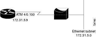
Note ![]() The Cisco IOS XE software supports no more than one PPP half-bridge per Ethernet subnetwork.
The Cisco IOS XE software supports no more than one PPP half-bridge per Ethernet subnetwork.
Multilink PPP
The Multilink PPP feature provides load balancing functionality over multiple WAN links, while providing multivendor interoperability, packet fragmentation and proper sequencing, and load calculation on both inbound and outbound traffic. The Cisco implementation of MLP supports the fragmentation and packet sequencing specifications in RFC 1990. Additionally, you can change the default endpoint discriminator value that is supplied as part of user authentication. Refer to RFC 1990 for more information about the endpoint discriminator.
MLP allows packets to be fragmented and the fragments to be sent at the same time over multiple point-to-point links to the same remote address. The multiple links come up in response to a defined dialer load threshold. The load can be calculated on inbound traffic, outbound traffic, or on either, as needed for the traffic between the specific sites. MLP provides bandwidth on demand and reduces transmission latency across WAN links.
MLP is designed to work over synchronous and asynchronous serial and BRI and PRI types of single or multiple interfaces that have been configured to support both dial-on-demand rotary groups and PPP encapsulation.
MLP Interleaving and Queueing
Interleaving on MLP allows large packets to be multilink encapsulated and fragmented into a small enough size to satisfy the delay requirements of real-time traffic; small real-time packets are not multilink encapsulated and are sent between fragments of the large packets. The interleaving feature also provides a special transmit queue for the smaller, delay-sensitive packets, enabling them to be sent earlier than other flows.
Weighted fair queueing on MLP works on the packet level, not at the level of multilink fragments. Thus, if a small real-time packet gets queued behind a larger best-effort packet and no special queue has been reserved for real-time packets, the small packet will be scheduled for transmission only after all the fragments of the larger packet are scheduled for transmission.
Weighted fair queueing is supported on all interfaces that support Multilink PPP, including MLP virtual access interfaces and virtual interface templates. Weighted fair-queueing is enabled by default.
Interleaving applies only to interfaces that can configure a multilink bundle interface.
Multilink and fair queueing are not supported when a multilink bundle is off-loaded to a different system using Multichassis Multilink PPP (MMP). Thus, interleaving is not supported in MMP networking designs.
How to Configure Media-Independent PPP and Multilink PPP
•![]() Enabling CHAP or PAP Authentication
Enabling CHAP or PAP Authentication
•![]() Enabling Link Quality Monitoring
Enabling Link Quality Monitoring
•![]() Configuring Compression of PPP Data
Configuring Compression of PPP Data
•![]() Configuring Microsoft Point-to-Point Compression
Configuring Microsoft Point-to-Point Compression
•![]() Configuring IP Address Pooling
Configuring IP Address Pooling
•![]() Configuring PPP Reliable Link
Configuring PPP Reliable Link
•![]() Disabling or Reenabling Peer Neighbor Routes
Disabling or Reenabling Peer Neighbor Routes
•![]() Configuring PPP Half-Bridging
Configuring PPP Half-Bridging
•![]() Configuring MLP Interleaving and Queueing
Configuring MLP Interleaving and Queueing
•![]() Disabling PPP Multilink Fragmentation
Disabling PPP Multilink Fragmentation
•![]() Monitoring and Maintaining PPP and MLP Interfaces
Monitoring and Maintaining PPP and MLP Interfaces
Enabling PPP Encapsulation
The encapsulation ppp command enables PPP on serial lines to encapsulate IP and other network protocol datagrams.
SUMMARY STEPS
1. ![]() enable
enable
2. ![]() configure terminal
configure terminal
3. ![]() configure fastethernet number
configure fastethernet number
4. ![]() encapsulation ppp
encapsulation ppp
5. ![]() end
end
DETAILED STEPS
Enabling CHAP or PAP Authentication
To enable CHAP or PAP authentication, perform the steps mentioned in this section.

For an example of CHAP, see the section "CHAP with an Encrypted Password Examples" section". CHAP is specified in RFC 1994, PPP Challenge Handshake Authentication Protocol (CHAP).
For information about MS-CHAP, see MS-CHAP Support.
SUMMARY STEPS
1. ![]() enable
enable
2. ![]() configure terminal
configure terminal
3. ![]() interface fastethernet number
interface fastethernet number
4. ![]() ppp authentication {chap | chap pap | pap chap | pap} [if-needed] [list-name | default] [callin]
ppp authentication {chap | chap pap | pap chap | pap} [if-needed] [list-name | default] [callin]
5. ![]() ppp use-tacacs [single-line]
ppp use-tacacs [single-line]
or
aaa authentication ppp
6. ![]() exit
exit
7. ![]() username name [user-maxlinks link-number] password secret
username name [user-maxlinks link-number] password secret
8. ![]() end
end
DETAILED STEPS
Enabling Link Quality Monitoring
Link Quality Monitoring (LQM) is available on all serial interfaces running PPP. LQM will monitor the link quality, and if the quality drops below a configured percentage, the router will shut down the link. The percentages are calculated for both the incoming and outgoing directions. The outgoing quality is calculated by comparing the total number of packets and bytes sent with the total number of packets and bytes received by the destination node. The incoming quality is calculated by comparing the total number of packets and bytes received with the total number of packets and bytes sent by the destination peer.
Note ![]() LQM is not compatible with Multilink PPP.
LQM is not compatible with Multilink PPP.
When LQM is enabled, Link Quality Reports (LQRs) are sent, in place of keepalives, every keepalive period. All incoming keepalives are responded to properly. If LQM is not configured, keepalives are sent every keepalive period and all incoming LQRs are responded to with an LQR.
LQR is specified in RFC 1989, PPP Link Quality Monitoring.
To enable LQM on the interface, use the following command in interface configuration mode:
SUMMARY STEPS
1. ![]() enable
enable
2. ![]() configure terminal
configure terminal
3. ![]() interface fastethernet number
interface fastethernet number
4. ![]() ppp quality percentage
ppp quality percentage
5. ![]() exit
exit
6. ![]() end
end
DETAILED STEPS
Configuring Compression of PPP Data
You can configure point-to-point software compression on serial interfaces that use PPP encapsulation. Compression reduces the size of a PPP frame via lossless data compression. PPP encapsulations support both predictor and Stacker compression algorithms.
If most of your traffic is already compressed files, do not use compression.
To configure software compression, perform the following task:
Software compression is available in all router platforms. Software compression is performed by the main processor in the router.
Compression is performed in software and might significantly affect system performance. We recommend that you disable compression if the router CPU load exceeds 65 percent. To display the CPU load, use the show process cpu EXEC command.
To configure compression over PPP, use the following commands in interface configuration mode:
SUMMARY STEPS
1. ![]() enable
enable
2. ![]() configure terminal
configure terminal
3. ![]() interface fastethernet number
interface fastethernet number
4. ![]() encapsulation ppp
encapsulation ppp
5. ![]() compress [predictor | stac | mppc [ignore-pfc]]
compress [predictor | stac | mppc [ignore-pfc]]
6. ![]() end
end
DETAILED STEPS
Configuring Microsoft Point-to-Point Compression
Perform this task to configure MPCC. This will help you set MPPC once PPP encapsulation is configured on the router.
Prerequisites
Ensure that PPP encapsulation is enabled before you configure MPPC.
Restrictions
The following restrictions apply to the MPPC feature:
•![]() MPPC is supported only with PPP encapsulation.
MPPC is supported only with PPP encapsulation.
•![]() Compression can be processor intensive because it requires a reserved block of memory to maintain the history buffer. Do not enable modem or hardware compression because it may cause performance degradation, compression failure, or data expansion.
Compression can be processor intensive because it requires a reserved block of memory to maintain the history buffer. Do not enable modem or hardware compression because it may cause performance degradation, compression failure, or data expansion.
•![]() Both ends of the point-to-point link must be using the same compression method (STAC, Predictor, or MPPC, for example).
Both ends of the point-to-point link must be using the same compression method (STAC, Predictor, or MPPC, for example).
SUMMARY STEPS
1. ![]() enable
enable
2. ![]() configure terminal
configure terminal
3. ![]() interface serial number
interface serial number
4. ![]() compress [mppc [ignore-pfc]]
compress [mppc [ignore-pfc]]
DETAILED STEPS
Examples
Following is sample debug ppp negotiation command output showing protocol reject:
PPP Async2: protocol reject received for protocol = 0x2145
PPP Async2: protocol reject received for protocol = 0x2145
PPP Async2: protocol reject received for protocol = 0x2145
Configuring IP Address Pooling
•![]() Choosing the IP Address Assignment Method
Choosing the IP Address Assignment Method
Choosing the IP Address Assignment Method
The IP address pooling feature now allows configuration of a global default address pooling mechanism, per-interface configuration of the address pooling mechanism, and per-interface configuration of a specific address or pool name.
You can define the type of IP address pooling mechanism used on router interfaces in one or both of the ways described in the following sections:
•![]() Defining the Global Default Address Pooling Mechanism
Defining the Global Default Address Pooling Mechanism
•![]() Configuring IP Address Assignment
Configuring IP Address Assignment
Defining the Global Default Address Pooling Mechanism
The global default mechanism applies to all point-to-point interfaces that support PPP encapsulation and that have not otherwise been configured for IP address pooling. You can define the global default mechanism to be either DHCP or local address pooling.
To configure the global default mechanism for IP address pooling, perform the tasks in one of following sections:
•![]() Defining DHCP as the Global Default Mechanism
Defining DHCP as the Global Default Mechanism
•![]() Defining Local Address Pooling as the Global Default Mechanism
Defining Local Address Pooling as the Global Default Mechanism
After you have defined a global default mechanism, you can disable it on a specific interface by configuring the interface for some other pooling mechanism. You can define a local pool other than the default pool for the interface or you can configure the interface with a specific IP address to be used for dial-in peers.
You can also control the DHCP network discovery mechanism; see the following section for more information:
•![]() Controlling DHCP Network Discovery
Controlling DHCP Network Discovery
Defining DHCP as the Global Default Mechanism
DHCP specifies the following components:
•![]() A DHCP server—A host-based DHCP server configured to accept and process requests for temporary IP addresses.
A DHCP server—A host-based DHCP server configured to accept and process requests for temporary IP addresses.
•![]() A DHCP proxy-client—A Cisco access server configured to arbitrate DHCP calls between the DHCP server and the DHCP client. The DHCP client-proxy feature manages a pool of IP addresses available to dial-in clients without a known IP address.
A DHCP proxy-client—A Cisco access server configured to arbitrate DHCP calls between the DHCP server and the DHCP client. The DHCP client-proxy feature manages a pool of IP addresses available to dial-in clients without a known IP address.
To enable DHCP as the global default mechanism, use the following commands in global configuration mode:
SUMMARY STEPS
1. ![]() enable
enable
2. ![]() configure terminal
configure terminal
3. ![]() ip address-pool dhcp-proxy-client
ip address-pool dhcp-proxy-client
4. ![]() ip dhcp-server [ip-address | name]
ip dhcp-server [ip-address | name]
5. ![]() end
end
DETAILED STEPS
Defining Local Address Pooling as the Global Default Mechanism
Note ![]() If no other pool is defined, a local pool called "default" is used. Optionally, you can associate an address pool with a named pool group.
If no other pool is defined, a local pool called "default" is used. Optionally, you can associate an address pool with a named pool group.
To specify that the global default mechanism to use is local pooling, use the following commands in global configuration mode:
SUMMARY STEPS
1. ![]() enable
enable
2. ![]() configure terminal
configure terminal
3. ![]() ip address-pool local
ip address-pool local
4. ![]() ip local pool {named-address-pool | default} first-IP-address [last-IP-address] [group group-name] [cache-size size]
ip local pool {named-address-pool | default} first-IP-address [last-IP-address] [group group-name] [cache-size size]
DETAILED STEPS
Controlling DHCP Network Discovery
To allow peer routers to dynamically discover Domain Name System (DNS) and NetBIOS name server information configured on a DHCP server using PPP IP Control Protocol (IPCP) extensions, use the following command in global configuration mode:
The ip dhcp-client network-discovery global configuration command provides a way to control the DHCP network discovery mechanism. The number of DHCP Inform or Discovery messages can be set to 1 or 2, which determines how many times the system sends the DHCP Inform or Discover messages before stopping network discovery. You can set a timeout period from 3 to 15 seconds, or leave the default timeout period at 15 seconds. The default for the informs and discovers keywords is 0, which disables the transmission of these messages.
SUMMARY STEPS
1. ![]() enable
enable
2. ![]() configure terminal
configure terminal
3. ![]() ip dhcp-client network-discovery informs number-of-messages discovers number-of-messages period seconds
ip dhcp-client network-discovery informs number-of-messages discovers number-of-messages period seconds
DETAILED STEPS
Configuring IP Address Assignment
After you have defined a global default mechanism for assigning IP addresses to dial-in peers, you can configure the few interfaces for which it is important to have a nondefault configuration. You can do any of the following;
•![]() Define a nondefault address pool for use by a specific interface.
Define a nondefault address pool for use by a specific interface.
•![]() Define DHCP on an interface even if you have defined local pooling as the global default mechanism.
Define DHCP on an interface even if you have defined local pooling as the global default mechanism.
•![]() Specify one IP address to be assigned to all dial-in peers on an interface.
Specify one IP address to be assigned to all dial-in peers on an interface.
•![]() Make temporary IP addresses available on a per-interface basis to asynchronous clients using SLIP or PPP.
Make temporary IP addresses available on a per-interface basis to asynchronous clients using SLIP or PPP.
To define a nondefault address pool for use on an interface, use the following commands beginning in global configuration mode:
SUMMARY STEPS
1. ![]() enable
enable
2. ![]() configure terminal
configure terminal
3. ![]() ip local pool {named-address-pool | default} {first-IP-address [last-IP-address]} [group group-name] [cache-size size]}
ip local pool {named-address-pool | default} {first-IP-address [last-IP-address]} [group group-name] [cache-size size]}
4. ![]() interface type number
interface type number
5. ![]() peer default ip address pool pool-name-list
peer default ip address pool pool-name-list
6. ![]() peer default ip address pool dhcp
peer default ip address pool dhcp
7. ![]() peer default ip address ip-address
peer default ip address ip-address
DETAILED STEPS
Configuring PPP Reliable Link
PPP reliable link is Cisco's implementation of RFC 1663, PPP Reliable Transmission, which defines a method of negotiating and using Numbered Mode Link Access Procedure, Balanced (LAPB) to provide a reliable serial link. Numbered Mode LAPB provides retransmission of error packets across the serial link.
Although LAPB protocol overhead consumes some bandwidth, you can offset that consumption by the use of PPP compression over the reliable link. PPP compression is separately configurable and is not required for use of a reliable link.
Note ![]() PPP reliable link is available only on synchronous serial interfaces. PPP reliable link cannot be used over V.120, and does not work with Multilink PPP.
PPP reliable link is available only on synchronous serial interfaces. PPP reliable link cannot be used over V.120, and does not work with Multilink PPP.
To configure PPP reliable link on a specified interface, use the following command in interface configuration mode:
SUMMARY STEPS
1. ![]() enable
enable
2. ![]() configure terminal
configure terminal
3. ![]() interface type number
interface type number
4. ![]() ppp reliable-link
ppp reliable-link
DETAILED STEPS
Troubleshooting PPP
You can troubleshoot PPP reliable link by using the debug lapb command and the debug ppp negotiations, debug ppp errors, and debug ppp packets commands. You can determine whether LAPB has been established on a connection by using the show interface command.
Disabling or Reenabling Peer Neighbor Routes
Cisco IOS XE software automatically creates neighbor routes by default; that is, it automatically sets up a route to the peer address on a point-to-point interface when the PPP IPCP negotiation is completed.
To disable this default behavior or to reenable it once it has been disabled, use the following commands in interface configuration mode:
SUMMARY STEPS
1. ![]() enable
enable
2. ![]() configure terminal
configure terminal
3. ![]() interface type number
interface type number
4. ![]() no peer neighbor-route
no peer neighbor-route
5. ![]() peer neighbor-route
peer neighbor-route
DETAILED STEPS
Configuring PPP Half-Bridging
To configure a serial interface to function as a half-bridge, use the following commands beginning in global configuration mode as appropriate for your network:
SUMMARY STEPS
1. ![]() enable
enable
2. ![]() configure terminal
configure terminal
3. ![]() interface type number
interface type number
4. ![]() ppp bridge appletalk
ppp bridge appletalk
or
ppp bridge ip
or
ppp bridge ipx [novell-ether | arpa | sap | snap]
5. ![]() ip address n.n.n.n
ip address n.n.n.n
or
appletalk address network.node
or
appletalk cable-range cable-range network.node
or
ipx network network
DETAILED STEPS
Configuring Multilink PPP
•![]() Configuring MLP on Synchronous Interfaces
Configuring MLP on Synchronous Interfaces
•![]() Assigning an Interface to a Multilink Bundle
Assigning an Interface to a Multilink Bundle
•![]() Configuring MLP Using Multilink Group Interfaces
Configuring MLP Using Multilink Group Interfaces
•![]() Configuring Multilink PPP Minimum Links Mandatory
Configuring Multilink PPP Minimum Links Mandatory
•![]() Changing the Default Endpoint Discriminator
Changing the Default Endpoint Discriminator
Configuring MLP on Synchronous Interfaces
To configure Multilink PPP on synchronous interfaces, you configure the synchronous interfaces to support PPP encapsulation and Multilink PPP.
To configure a synchronous interface, use the following commands beginning in global configuration mode:
SUMMARY STEPS
1. ![]() enable
enable
2. ![]() configuration terminal
configuration terminal
3. ![]() interface serial 1
interface serial 1
4. ![]() no ip address
no ip address
5. ![]() encapuslation ppp
encapuslation ppp
6. ![]() ppp multilink
ppp multilink
7. ![]() pulse-time seconds
pulse-time seconds
DETAILED STEPS
Creating a Multilink Bundle
To create a multilink bundle, use the following commands beginning in global configuration mode:
SUMMARY STEPS
1. ![]() enable
enable
2. ![]() configure terminal
configure terminal
3. ![]() interface multilink group-number
interface multilink group-number
4. ![]() ip address address mask
ip address address mask
5. ![]() encapsulation ppp
encapsulation ppp
6. ![]() ppp multilink
ppp multilink
DETAILED STEPS
Assigning an Interface to a Multilink Bundle
Perform this task to assign an interface to a multilink bundle.
SUMMARY STEPS
1. ![]() enable
enable
2. ![]() configure terminal
configure terminal
3. ![]() interface multilink group number
interface multilink group number
4. ![]() no ip address
no ip address
5. ![]() keepalive
keepalive
6. ![]() encapsulation ppp
encapsulation ppp
7. ![]() ppp multilink group group-number
ppp multilink group group-number
8. ![]() ppp multilink
ppp multilink
9. ![]() ppp authentication chap
ppp authentication chap
10. ![]() pulse-time seconds
pulse-time seconds
DETAILED STEPS
Configuring MLP Using Multilink Group Interfaces
MLP can be configured by assigning a multilink group to a virtual template configuration. Virtual templates allow a virtual access interface to dynamically clone interface parameters from the specified virtual template. If a multilink group is assigned to a virtual template, and then the virtual template is assigned to a physical interface, all links that pass through the physical interface will belong to the same multilink bundle.
Note ![]() If a multilink group interface has one member link, the amount of bandwidth available will not change when a multilink interface is shut down. Therefore, you can shut down the multilink interface by removing its link.
If a multilink group interface has one member link, the amount of bandwidth available will not change when a multilink interface is shut down. Therefore, you can shut down the multilink interface by removing its link.
A multilink group interface configuration will override a global multilink virtual template configured with the multilink virtual template command.
Multilink group interfaces can be used with ATM, PPP over Frame Relay, and serial interfaces.
To configure MLP using a multilink group interface, perform the following tasks:
•![]() Configure the multilink group.
Configure the multilink group.
•![]() Assign the multilink group to a virtual template.
Assign the multilink group to a virtual template.
•![]() Configure the physical interface to use the virtual template.
Configure the physical interface to use the virtual template.
SUMMARY STEPS
1. ![]() enable
enable
2. ![]() configure terminal
configure terminal
3. ![]() interface multilink group-number
interface multilink group-number
4. ![]() ip address address mask
ip address address mask
5. ![]() encapsulation ppp
encapsulation ppp
6. ![]() exit
exit
7. ![]() interface virtual template number
interface virtual template number
8. ![]() ppp multilink group group-number
ppp multilink group group-number
9. ![]() exit
exit
10. ![]() interface atm interface-number.subinterface-number point-to-point
interface atm interface-number.subinterface-number point-to-point
11. ![]() pvc vpi/vli
pvc vpi/vli
12. ![]() protocol ppp virtual-template name
protocol ppp virtual-template name
13. ![]() end
end
DETAILED STEPS
Configuring Multilink PPP Minimum Links Mandatory
Perform this task to configure the minimum number of links in an MLP bundle required to keep that bundle active.
SUMMARY STEPS
1. ![]() enable
enable
2. ![]() configure terminal
configure terminal
3. ![]() ppp multilink
ppp multilink
4. ![]() ppp multilink min-links links mandatory
ppp multilink min-links links mandatory
DETAILED STEPS
Changing the Default Endpoint Discriminator
By default, when the system negotiates use of MLP with the peer, the value that is supplied for the endpoint discriminator is the same as the username used for authentication. That username is configured for the interface by the Cisco IOS ppp chap hostname or ppp pap sent-username command, or defaults to the globally configured host name (or stack group name, if this interface is a Stack Group Bidding Protocol, or SGBP, group member).
Perform this task to override or change the default endpoint discriminator.
SUMMARY STEPS
1. ![]() enable
enable
2. ![]() configure terminal
configure terminal
3. ![]() interface virutal template number
interface virutal template number
4. ![]() ppp multilink endpoint {hostname | ip ipaddress | mac LAN-interface | none | phone telephone-number | string char-string}
ppp multilink endpoint {hostname | ip ipaddress | mac LAN-interface | none | phone telephone-number | string char-string}
DETAILED STEPS
Configuring MLP Interleaving and Queueing
MLP support for interleaving can be configured on virtual templates. To configure interleaving, complete the following tasks:
•![]() Configure the virtual template.
Configure the virtual template.
•![]() Configure MLP and interleaving on the interface or template.
Configure MLP and interleaving on the interface or template.
Note ![]() Fair queueing, which is enabled by default, must remain enabled on the interface.
Fair queueing, which is enabled by default, must remain enabled on the interface.
Configuring MLP Interleaving
Note ![]() Interleaving statistics can be displayed by using the show interfaces command, specifying the particular interface on which interleaving is enabled. Interleaving data is displayed only if there are interleaves. For example, the following line shows interleaves: Output queue: 315/64/164974/31191 (size/threshold/drops/interleaves)
Interleaving statistics can be displayed by using the show interfaces command, specifying the particular interface on which interleaving is enabled. Interleaving data is displayed only if there are interleaves. For example, the following line shows interleaves: Output queue: 315/64/164974/31191 (size/threshold/drops/interleaves)
Perform this task to configure MLP Interleaving.
SUMMARY STEPS
1. ![]() enable
enable
2. ![]() configure terminal
configure terminal
3. ![]() interface virtual template number
interface virtual template number
4. ![]() ppp multilink
ppp multilink
5. ![]() ppp multilink interleave
ppp multilink interleave
6. ![]() ppp multilink fragment delay milliseconds
ppp multilink fragment delay milliseconds
7. ![]() ip rtp reserve lowest-udp-port range-of-ports [maximum-bandwidth]
ip rtp reserve lowest-udp-port range-of-ports [maximum-bandwidth]
8. ![]() exit
exit
9. ![]() multilink virtual-template virtual-template-number
multilink virtual-template virtual-template-number
DETAILED STEPS
Disabling PPP Multilink Fragmentation
Perform the following task to disable PPP multilink fragmentation.
SUMMARY STEPS
1. ![]() enable
enable
2. ![]() configuration terminal
configuration terminal
3. ![]() interface multilink group number
interface multilink group number
4. ![]() ppp multilink fragment disable
ppp multilink fragment disable
5. ![]() exit
exit
DETAILED STEPS
Monitoring and Maintaining PPP and MLP Interfaces
Perform this task to display MLP and MMP bundle information.
SUMMARY STEPS
1. ![]() enable
enable
2. ![]() show ppp multilink
show ppp multilink
3. ![]() exit
exit
DETAILED STEPS
Configuration Examples for PPP and MLP
•![]() Multilink PPP with Traffic Shaping Example
Multilink PPP with Traffic Shaping Example
•![]() CHAP with an Encrypted Password Examples
CHAP with an Encrypted Password Examples
•![]() MLP on Synchronous Serial Interfaces Example
MLP on Synchronous Serial Interfaces Example
•![]() MLP Using Multilink Group Interfaces over ATM Example
MLP Using Multilink Group Interfaces over ATM Example
•![]() MLP Interleaving and Queueing for Real-Time Traffic Example
MLP Interleaving and Queueing for Real-Time Traffic Example
Multilink PPP with Traffic Shaping Example
The following example shows the configuration of multilink PPP with traffic shaping and QoS. In this example two bundles, with four links in each bundle, are configured between two devices. The ppp chap hostname command entries are required for originating and terminating multiple bundles on a single pair of devices.
controller T3 0/3/1
framing c-bit
cablelength 224
t1 1 channel-group 0 timeslots 1-24
t1 2 channel-group 0 timeslots 1-24
t1 3 channel-group 0 timeslots 1-24
t1 4 channel-group 0 timeslots 1-24
t1 5 channel-group 0 timeslots 1-24
t1 6 channel-group 0 timeslots 1-24
t1 7 channel-group 0 timeslots 1-24
t1 8 channel-group 0 timeslots 1-24
!
class-map match-all DETERMINISTICOUT
match ip precedence 3
class-map match-all VOICEVIDEOCONTROLOUT
match ip precedence 2
class-map match-all VOICEOUT
match ip precedence 1
class-map match-all ROUTINGPROTOCOLS
match ip precedence 5
class-map match-all CONTROLLEDLOADOUT
match ip precedence 4
!
policy-map QOS304QCHILD
class VOICEOUT
priority level 1
police cir percent 30
class VOICEVIDEOCONTROLOUT
priority level 2
police cir percent 5
class DETERMINISTICOUT
bandwidth remaining ratio 20
class CONTROLLEDLOADOUT
bandwidth remaining ratio 18
class ROUTINGPROTOCOLS
bandwidth remaining ratio 4
class class-default
bandwidth remaining ratio 22
policy-map ASRMLPPP6MBPARENT
class class-default
shape average percent 98
service-policy QOS304QCHILD
!
interface Multilink1
ip address 192.168.1.1 255.255.255.0
ppp chap hostname multilink_name-1
ppp multilink
ppp multilink group 1
service-policy output ASRMLPPP6MBPARENT
!
interface Multilink2
ip address 192.168.2.1 255.255.255.0
ppp chap hostname multilink_name-2
ppp multilink
ppp multilink group 2
service-policy output ASRMLPPP6MBPARENT
!
interface Serial0/3/1/1:0
no ip address
encapsulation ppp
no keepalive
ppp chap hostname multilink_name-1
ppp multilink
ppp multilink group 1
!
interface Serial0/3/1/2:0
no ip address
encapsulation ppp
no keepalive
ppp chap hostname multilink_name-1
ppp multilink
ppp multilink group 1
!
interface Serial0/3/1/3:0
no ip address
encapsulation ppp
no keepalive
ppp chap hostname multilink_name-1
ppp multilink
ppp multilink group 1
!
interface Serial0/3/1/4:0
no ip address
encapsulation ppp
no keepalive
ppp chap hostname multilink_name-1
ppp multilink
ppp multilink group 1
!
interface Serial0/3/1/5:0
no ip address
encapsulation ppp
no keepalive
ppp chap hostname multilink_name-2
ppp multilink
ppp multilink group 2
!
interface Serial0/3/1/6:0
no ip address
encapsulation ppp
no keepalive
ppp chap hostname multilink_name-2
ppp multilink
ppp multilink group 2
!
interface Serial0/3/1/7:0
no ip address
encapsulation ppp
no keepalive
ppp chap hostname multilink_name-2
ppp multilink
ppp multilink group 2
!
interface Serial0/3/1/8:0
no ip address
encapsulation ppp
no keepalive
ppp chap hostname multilink_name-2
ppp multilink
ppp multilink group 2
!
CHAP with an Encrypted Password Examples
The following examples show how to enable CHAP on serial interface 0 of three devices:
Configuration of Router yyy
hostname yyy
interface serial 0/0/0
encapsulation ppp
ppp authentication chap
username xxx password secretxy
username zzz password secretzy
Configuration of Router xxx
hostname xxx
interface serial 0/0/0
encapsulation ppp
ppp authentication chap
username yyy password secretxy
username zzz password secretxz
Configuration of Router zzz
hostname zzz
interface serial 0/0/0
encapsulation ppp
ppp authentication chap
username xxx password secretxz
username yyy password secretzy
When you look at the configuration file, the passwords will be encrypted and the display will look similar to the following:
hostname xxx
interface serial 0/0/0
encapsulation ppp
ppp authentication chap
username yyy password 7 121F0A18
username zzz password 7 1329A055
MLP on Synchronous Serial Interfaces Example
MLP provides characteristics most similar to hardware inverse multiplexers, with good manageability and Layer 3 services support. Figure 2 shows a typical inverse multiplexing application using two Cisco routers and Multilink PPP over four T1 lines.
Figure 2 Inverse Multiplexing Application Using Multilink PPP
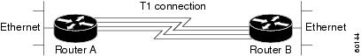
The following example shows the configuration commands used to create the inverse multiplexing application:
Router A Configuration
hostname RouterA
!
!
username RouterB password your_password
ip subnet-zero
multilink virtual-template 1
!
interface Virtual-Template1
ip unnumbered Ethernet0
ppp authentication chap
ppp multilink
!
interface Serial0
no ip address
encapsulation ppp
no fair-queue
ppp multilink
pulse-time 3
!
interface Serial1
no ip address
encapsulation ppp
no fair-queue
ppp multilink
pulse-time 3
!
interface Serial2
no ip address
encapsulation ppp
no fair-queue
ppp multilink
pulse-time 3
!
interface Serial3
no ip address
encapsulation ppp
no fair-queue
ppp multilink
pulse-time 3
!
interface GigabitEthernet0/0/0
ip address 10.17.1.254 255.255.255.0
!
router rip
network 10.0.0.0
!
end
Router B Configuration
hostname RouterB
!
!
username RouterB password your_password
ip subnet-zero
multilink virtual-template 1
!
interface Virtual-Template1
ip unnumbered Ethernet0
ppp authentication chap
ppp multilink
!
interface Serial0
no ip address
encapsulation ppp
no fair-queue
ppp multilink
pulse-time 3
!
interface Serial1
no ip address
encapsulation ppp
no fair-queue
ppp multilink
pulse-time 3
!
interface Serial2
no ip address
encapsulation ppp
no fair-queue
ppp multilink
pulse-time 3
!
interface Serial3
no ip address
encapsulation ppp
no fair-queue
ppp multilink
pulse-time 3
!
interface Ethernet0
ip address 10.17.2.254 255.255.255.0
!
router rip
network 10.0.0.0
!
end
MLP Using Multilink Group Interfaces over ATM Example
The following example configures MLP over an ATM PVC using a multilink group:
interface multilink 1
ip address 10.200.83.106 255.255.255.252
ip tcp header-compression iphc-format delay 20000
service policy output xyz
encapsulation ppp
ppp multilink
ppp multilink fragment delay 10
ppp multilink interleave
ppp timeout multilink link remove 10
ip rtp header-compression iphc-format
interface virtual-template 3
bandwidth 128
ppp multilink group 1
interface atm 4/0.1 point-to-point
pvc 0/32
abr 100 80
protocol ppp virtual-template 3
.
MLP Interleaving and Queueing for Real-Time Traffic Example
The following example defines a virtual interface template that enables MLP interleaving and a maximum real-time traffic delay of 20 milliseconds, and then applies that virtual template to the MLP bundle:
interface virtual-template 1
ip unnumbered ethernet 0
ppp multilink
ppp multilink interleave
ppp multilink fragment delay 20
ip rtp interleave 32768 20 1000
multilink virtual-template 1
Additional References
Related Documents
|
|
|
|---|---|
PPP commands |
MIBs
Technical Assistance
Feature Information for Media-Independent PPP and Multilink PPP
Table 1 lists the features in this module and provides links to specific configuration information.
Use Cisco Feature Navigator to find information about platform support and software image support. Cisco Feature Navigator enables you to determine which Cisco IOS XE software images support a specific software release, feature set, or platform. To access Cisco Feature Navigator, go to http://tools.cisco.com/ITDIT/CFN/jsp/index.jsp. An account on Cisco.com is not required.
Note ![]() Table 1 lists only the Cisco IOS XE software release that introduced support for a given feature in a given Cisco IOS XE software release train. Unless noted otherwise, subsequent releases of that Cisco IOS XE software release train also support that feature.
Table 1 lists only the Cisco IOS XE software release that introduced support for a given feature in a given Cisco IOS XE software release train. Unless noted otherwise, subsequent releases of that Cisco IOS XE software release train also support that feature.
|
|
|
|
|---|---|---|
Media-Independent PPP and Multilink PPP |
Cisco IOS XE Release 2.1 |
This feature was introduced on Cisco ASR 1000 Series Routers. |
Multilink PPP Minimum Links Mandatory |
Cisco IOS XE Release 2.1 |
The Multilink PPP Minimum Links Mandatory feature enables you to configure the minimum number of links in a MLP bundle required to keep that bundle active. The following sections provide information about this feature: • • The following commands were introduced or modified: multilink min-links, ppp multilink links minimum. |
DHCP Proxy Client |
Cisco IOS XE Release 2.3 |
The DHCP proxy client feature allows you to manage a pool of IP addresses available to PPP or SLIP dial-in clients without a known IP address. The following section provides information about this feature: |
 Feedback