Cisco IOS XE Security Configuration Guide: Securing the Data Plane, Release 2
Bias-Free Language
The documentation set for this product strives to use bias-free language. For the purposes of this documentation set, bias-free is defined as language that does not imply discrimination based on age, disability, gender, racial identity, ethnic identity, sexual orientation, socioeconomic status, and intersectionality. Exceptions may be present in the documentation due to language that is hardcoded in the user interfaces of the product software, language used based on RFP documentation, or language that is used by a referenced third-party product. Learn more about how Cisco is using Inclusive Language.
- Updated:
- February 18, 2011
Chapter: Zone-based Policy Firewall
- Finding Feature Information
- Contents
- Prerequisites for Zone-Based Policy Firewall
- Restrictions for Zone-Based Policy Firewall
- Information About Zone-Based Policy Firewall
- Top-level Class Maps and Policy Maps
- Overview of Zones
- Security Zones
- Virtual Interfaces as Members of Security Zones
- Zone Pairs
- Zones and Inspection
- Zones and ACLs
- Overview of Security Zone Firewall Policies
- Class Maps and Policy Maps for Zone-Based Policy Firewalls
- Layer 3 and Layer 4 Class Maps and Policy Maps
- Class-Map Configuration Restriction
- Class-Default Class Map
- Access Control List and Class Map
- Firewall and Network Address Translation
- WAAS and Firewall Integration Support
- WAAS Traffic Flow Optimization Deployment Scenarios
- Configuring Layer 3 and Layer 4 Firewall Policies
- Configuring an Inspect Parameter Map
- Configuring NetFlow Event Logging
- Creating Security Zones and Zone Pairs, and Attaching a Policy Map to a Zone Pair
- Configuring the Firewall with WAAS
- Configuring an LDAP-Enabled Firewall
- Configuring an SCCP-Enabled Firewall
Zone-Based Policy Firewall
This module describes the Cisco IOS XE unidirectional firewall policy between groups of interfaces known as zones.
Finding Feature Information
Your software release may not support all the features documented in this module. For the latest feature information and caveats, see the release notes for your platform and software release. To find information about the features documented in this module, and to see a list of the releases in which each feature is supported, see the "Feature Information for Zone-Based Policy Firewall" section.
Use Cisco Feature Navigator to find information about platform support and Cisco software image support. To access Cisco Feature Navigator, go to http://www.cisco.com/go/cfn. An account on Cisco.com is not required.
Contents
•![]() Prerequisites for Zone-Based Policy Firewall
Prerequisites for Zone-Based Policy Firewall
•![]() Restrictions for Zone-Based Policy Firewall
Restrictions for Zone-Based Policy Firewall
•![]() Information About Zone-Based Policy Firewall
Information About Zone-Based Policy Firewall
•![]() How to Configure Zone-Based Policy Firewall
How to Configure Zone-Based Policy Firewall
•![]() Configuration Examples for Zone-Based Policy Firewall
Configuration Examples for Zone-Based Policy Firewall
•![]() Feature Information for Zone-Based Policy Firewall
Feature Information for Zone-Based Policy Firewall
Prerequisites for Zone-Based Policy Firewall
The general guideline before you create zones is that you should group interfaces that are similar when they are viewed from a security perspective.
Restrictions for Zone-Based Policy Firewall
•![]() Application-level maps (also referred to as Layer 7 class maps) are not supported in Cisco IOS XE software.
Application-level maps (also referred to as Layer 7 class maps) are not supported in Cisco IOS XE software.
•![]() In a Cisco Wide Area Application Services (WAAS) and Cisco IOS XE firewall configuration, all packets processed by a Wide Area Application Engine (WAE) device must go over the Cisco IOS XE firewall in both directions to support the Web Cache Coordination Protocol (WCCP) generic routing encapsulation (GRE) redirect. This situation occurs when the Layer 2 redirect is not available. If Layer 2 redirect is configured on the WAE, the system defaults to the GRE redirect to continue to function.
In a Cisco Wide Area Application Services (WAAS) and Cisco IOS XE firewall configuration, all packets processed by a Wide Area Application Engine (WAE) device must go over the Cisco IOS XE firewall in both directions to support the Web Cache Coordination Protocol (WCCP) generic routing encapsulation (GRE) redirect. This situation occurs when the Layer 2 redirect is not available. If Layer 2 redirect is configured on the WAE, the system defaults to the GRE redirect to continue to function.
•![]() When an in-to-out zone-based policy is configured to match the Internet Control Message Protocol (ICMP) on a Windows system, the traceroute command works. However, the same configuration on an Apple system does not work because it uses a UDP-based traceroute. To overcome this issue, configure an out-to-in zone-based policy with the icmp time-exceeded and icmp host unreachable commands with the pass command (not the inspect command).
When an in-to-out zone-based policy is configured to match the Internet Control Message Protocol (ICMP) on a Windows system, the traceroute command works. However, the same configuration on an Apple system does not work because it uses a UDP-based traceroute. To overcome this issue, configure an out-to-in zone-based policy with the icmp time-exceeded and icmp host unreachable commands with the pass command (not the inspect command).
•![]() In a WAAS and Cisco IOS XE firewall configuration, WCCP does not support traffic redirection using policy-based routing (PBR).
In a WAAS and Cisco IOS XE firewall configuration, WCCP does not support traffic redirection using policy-based routing (PBR).
•![]() Stateful inspection support for multicast traffic is not supported between any zones, including the self zone. Use Control Plane Policing for protection of the control plane against multicast traffic.
Stateful inspection support for multicast traffic is not supported between any zones, including the self zone. Use Control Plane Policing for protection of the control plane against multicast traffic.
•![]() A UDP-based traceroute is not supported through ICMP inspection.
A UDP-based traceroute is not supported through ICMP inspection.
Information About Zone-Based Policy Firewall
•![]() Top-level Class Maps and Policy Maps
Top-level Class Maps and Policy Maps
•![]() Virtual Interfaces as Members of Security Zones
Virtual Interfaces as Members of Security Zones
•![]() Overview of Security Zone Firewall Policies
Overview of Security Zone Firewall Policies
•![]() Class Maps and Policy Maps for Zone-Based Policy Firewalls
Class Maps and Policy Maps for Zone-Based Policy Firewalls
•![]() Layer 3 and Layer 4 Class Maps and Policy Maps
Layer 3 and Layer 4 Class Maps and Policy Maps
•![]() Class-Map Configuration Restriction
Class-Map Configuration Restriction
•![]() Access Control List and Class Map
Access Control List and Class Map
•![]() Firewall and Network Address Translation
Firewall and Network Address Translation
•![]() WAAS and Firewall Integration Support
WAAS and Firewall Integration Support
•![]() WAAS Traffic Flow Optimization Deployment Scenarios
WAAS Traffic Flow Optimization Deployment Scenarios
Top-level Class Maps and Policy Maps
Top-level class maps allow you to identify the traffic stream at a high level. This is accomplished by using match access-group and match protocol commands. Top-level class maps are also referred to as Layer 3 and Layer 4 class maps.
Top-level policy maps allow you to define high-level actions by using the inspect, drop, and pass keywords. You can attach the policy maps to a target (zone pair).

Note ![]() Only inspect type policies can be configured on a zone pair.
Only inspect type policies can be configured on a zone pair.
Overview of Zones
A zone is a group of interfaces that have similar functions or features. They provide a way for you to specify where a Cisco IOS XE software firewall is applied.
For example, on a router, gigabit ethernet interface 0/0/0 and gigabit ethernet interface 0/0/1 may be connected to the local LAN. These two interfaces are similar because they represent the internal network, so they can be grouped into a zone for firewall configurations.
By default, the traffic between interfaces in the same zone is not be subjected to any policy. The traffic passes freely. Firewall zones are used for security features.
Note ![]() Zones may not span interfaces in different VPN routing and forwarding (VRF) instances.
Zones may not span interfaces in different VPN routing and forwarding (VRF) instances.
Security Zones
A security zone is a group of interfaces to which a policy can be applied.
Grouping interfaces into zones involves the following two procedures:
•![]() Creating a zone so that interfaces can be attached to it.
Creating a zone so that interfaces can be attached to it.
•![]() Configuring an interface to be a member of a given zone.
Configuring an interface to be a member of a given zone.
By default, traffic flows among interfaces that are members of the same zone.
When an interface is a member of a security zone, all traffic to and from that interface (except traffic going to the router or initiated by the router) is dropped. To permit traffic to and from a zone-member interface, you must make that zone part of a zone pair and then apply a policy to that zone pair. If the policy permits traffic (through inspect or pass actions), traffic can flow through the interface.
Basic rules to consider when setting up your zones are as follows:
•![]() Traffic from a zone interface to a nonzone interface or from a nonzone interface to a zone interface is always dropped.
Traffic from a zone interface to a nonzone interface or from a nonzone interface to a zone interface is always dropped.
•![]() Traffic between two zone interfaces is inspected if there is a zone pair relationship for each zone and if there is a configured policy for that zone pair.
Traffic between two zone interfaces is inspected if there is a zone pair relationship for each zone and if there is a configured policy for that zone pair.
•![]() By default, all traffic between two interfaces in the same zone is always allowed as if the "pass" action is configured.
By default, all traffic between two interfaces in the same zone is always allowed as if the "pass" action is configured.
•![]() A zone pair can be configured with a zone as both the source and the destination zones. An inspect policy can be configured on this zone pair to inspect or drop the traffic between two interfaces in the same zone.
A zone pair can be configured with a zone as both the source and the destination zones. An inspect policy can be configured on this zone pair to inspect or drop the traffic between two interfaces in the same zone.
For traffic to flow among all the interfaces in a router, all the interfaces must be a member of one security zone or another.
It is not necessary for all router interfaces to be members of security zones.
Figure 1 illustrates the following:
•![]() Interfaces E0 and E1 are members of security zone Z1.
Interfaces E0 and E1 are members of security zone Z1.
•![]() Interface E2 is a member of security zone Z2.
Interface E2 is a member of security zone Z2.
•![]() Interface E3 is not a member of any security zone.
Interface E3 is not a member of any security zone.
Figure 1 Security Zone Restrictions
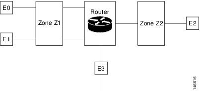
The following situations exist:
•![]() The zone pair and policy are configured in the same zone. Traffic flows freely between interfaces E0 and E1 because they are members of the same security zone (Z1).
The zone pair and policy are configured in the same zone. Traffic flows freely between interfaces E0 and E1 because they are members of the same security zone (Z1).
•![]() If no policies are configured, traffic will not flow between any other interfaces (for example, E0 and E2, E1 and E2, E3 and E1, and E3 and E2).
If no policies are configured, traffic will not flow between any other interfaces (for example, E0 and E2, E1 and E2, E3 and E1, and E3 and E2).
•![]() Traffic can flow between E0 or E1 and E2 only when an explicit policy permitting traffic is configured between zone Z1 and zone Z2.
Traffic can flow between E0 or E1 and E2 only when an explicit policy permitting traffic is configured between zone Z1 and zone Z2.
•![]() Traffic can never flow between E3 and E0/E1/E2 unless default zones are enabled.
Traffic can never flow between E3 and E0/E1/E2 unless default zones are enabled.
Virtual Interfaces as Members of Security Zones
A virtual interface is a logical interface configured with generic configuration information for a specific purpose or for configuration common to specific users, plus router-dependent information. The template contains Cisco IOS XE software interface commands that are applied to virtual access interfaces, as needed. To configure a virtual template interface, use the interface virtual-template command.
Zone member information is acquired from a RADIUS server and then the dynamically created interface is made a member of that zone.
The zone-member security command puts the dynamic interface into the corresponding zone.
Zone Pairs
A zone pair allows you to specify a unidirectional firewall policy between two security zones.
To define a zone pair, use the zone-pair security command. The direction of the traffic is specified by specifying a source and a destination zone. The source and destination zones of a zone pair must be security zones.
If desired, you can select the default or self zone as either the source or the destination zone. The self zone is a system-defined zone. It does not have any interfaces as members. A zone pair that includes the self zone, along with the associated policy, applies to traffic directed to the router or traffic generated by the router. It does not apply to traffic through the router.
The most common usage of firewalls is to apply them to traffic through a router, so you usually need at least two zones (that is, you cannot use the self zone).
To permit traffic between zone-member interfaces, you must configure a policy permitting (or inspecting) traffic between that zone and another zone. To attach a firewall policy map to the target zone pair, use the service-policy type inspect command.
Figure 2 shows the application of a firewall policy to traffic flowing from zone Z1 to zone Z2, which means that the ingress interface for the traffic is a member of zone Z1 and the egress interface is a member of zone Z2.
Figure 2 Zone Pairs
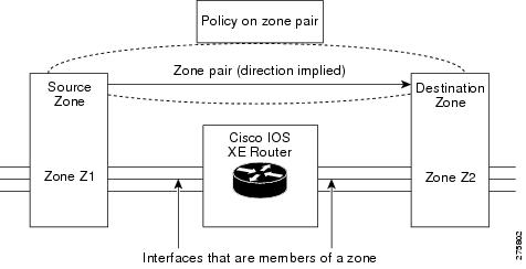
If there are two zones and you require policies for traffic going in both directions (from Z1 to Z2 and Z2 to Z1), you must configure two zone pairs (one for each direction).
If a policy is not configured between a pair of zones, traffic is dropped. However, it is not necessary to configure a zone pair and a service policy solely for return traffic. Return traffic is allowed, by default, if a service policy permits the traffic in the forward direction. In Figure 2, it is not mandatory that you configure a zone-pair source Z2 destination Z1 solely for allowing return traffic from Z2 to Z1. The service policy on the Z1-Z2 zone pair takes care of it.
Zones and Inspection
Zone-based policy firewalls examine the source and destination zones from the ingress and egress interfaces for a firewall policy. It is not necessary that all traffic flowing to or from an interface be inspected; you can designate that individual flows in a zone pair be inspected through your policy map that you apply across the zone pair. The policy map will contain class maps that specify the individual flows.
You can also configure inspect parameters like TCP thresholds and timeouts on a per-flow basis.
Zones and ACLs
Pinholes are not punched for return traffic in interface Access Control List (ACL).
ACLs applied to interfaces that are members of zones are processed before the policy is applied on the zone pair. So, you must relax interface ACLs when there are policies between zones so that they cannot interfere with the policy firewall traffic.
Overview of Security Zone Firewall Policies
A class is a way of identifying a set of packets based on its contents. Normally you define a class so that you can apply an action on the identified traffic that reflects a policy. A class is designated through class maps.
An action is a specific functionality. It typically is associated with a traffic class. For example, inspect, drop, and pass are actions.
To create firewall policies, you should complete the following tasks:
•![]() Define a match criteria (class map)
Define a match criteria (class map)
•![]() Associate actions to the match criteria (policy map)
Associate actions to the match criteria (policy map)
•![]() Attach the policy map to a zone pair (service policy)
Attach the policy map to a zone pair (service policy)
The class-map command creates a class map to be used for matching packets to a specified class. Packets arriving at the targets (such as the input interface, output interface, or zone-pair), determined by how the service-policy command is configured, are checked against the match criteria configured for a class map to determine if the packet belongs to that class.
The policy-map command creates or modifies a policy map that can be attached to one or more targets to specify a service policy. Use the policy-map command to specify the name of the policy map to be created, added to, or modified before you can configure policies for classes whose match criteria are defined in a class map.
Class Maps and Policy Maps for Zone-Based Policy Firewalls
Quality of service (QoS) class maps have numerous match criteria; firewalls have fewer match criteria. Firewall class maps have type inspect; this information controls what shows up under firewall class maps.
A policy is an association of traffic classes and actions. It specifies what actions should be performed on the defined traffic classes. An action is a specific function, and it is typically associated with a traffic class. For example, inspect and drop are actions.
Layer 3 and Layer 4 Class Maps and Policy Maps
Layer 3 and Layer 4 class maps are used to identify traffic streams on which different actions should be performed.
A Layer 3 or Layer 4 policy map is sufficient for the basic inspection of traffic.
The following example shows how to configure class map c1 with the match criteria of ACL 101 and the FTP protocol, and create an inspect policy map named p1 to specify that packets will be dropped on the traffic at c1:
Router(config)# class-map type inspect match-all c1
Router(config-cmap)# match access-group 101
Router(config-cmap)# match protocol ftp
Router(config)# policy-map type inspect p1
Router(config-pmap)# class type inspect c1
Router(config-pmap-c)# drop
Supported Protocols
The following protocols are supported:
•![]() FTP
FTP
•![]() H.323
H.323
•![]() ICMP
ICMP
•![]() Lightweight Directory Access Protocol (LDAP)
Lightweight Directory Access Protocol (LDAP)
•![]() LDAP over Transport Layer Security/Secure Socket Layer (LDAPS)
LDAP over Transport Layer Security/Secure Socket Layer (LDAPS)
•![]() Real-time Streaming Protocol (RTSP)
Real-time Streaming Protocol (RTSP)
•![]() Session Initiation Protocol (SIP)
Session Initiation Protocol (SIP)
•![]() SCCP (Skinny Client Control Protocol)
SCCP (Skinny Client Control Protocol)
•![]() TCP
TCP
•![]() TFTP
TFTP
•![]() UDP
UDP
Class-Map Configuration Restriction
If traffic meets multiple match criteria, the match criteria must be applied in the order of specific to less specific. For example, consider the following class map example:
class-map type inspect match-any my-test-cmap
match protocol ftp
match protocol tcp
In this example, FTP traffic must first encounter the match protocol ftp command to ensure that the traffic will be handled by the service-specific capabilities of FTP inspection. If the "match" lines were reversed so traffic encountered the match protocol tcp command before it was compared to the match protocol ftp command, the traffic would simply be classified as TCP traffic and inspected according to the capabilities of the Firewall's TCP Inspection component.
Class-Default Class Map
In addition to user-defined classes, a system-defined class map named class-default represents all packets that do not match any of the user-defined classes in a policy. It always is the last class in a policy map.
You can define explicit actions for this group of packets. If you do not configure any actions for class default in an inspect policy, the default action is drop.
Access Control List and Class Map
Access Control Lists (ACLs) are commonly implemented on Cisco routers. Access lists are packet-classifying mechanisms. These access lists define actual network traffic that will be permitted or denied when it is applied to a particular router network interface. Thus, the ACL is a sequential collection of permit and deny conditions that applies to a packet. The router tests packets against the conditions in the ACL one at a time. A deny condition is interpreted as "do not match." Packets matching a deny access control entry (ACE) cause an ACL process to terminate and the next match statement within the class to be examined.
Class maps are used to match a range of variables in an access list based on the following criteria:
•![]() If a class map does not find a match or matches a permit or deny, then the ACL fails.
If a class map does not find a match or matches a permit or deny, then the ACL fails.
•![]() If the class map is specified then the class map performs either an AND (match-all) or an OR (match-any) operation on these variables.
If the class map is specified then the class map performs either an AND (match-all) or an OR (match-any) operation on these variables.
•![]() If a match-all attribute is specified and any match, ACL, or protocol fails to match the packet, then further evaluation of the current class is stopped, and the next class in the policy is examined.
If a match-all attribute is specified and any match, ACL, or protocol fails to match the packet, then further evaluation of the current class is stopped, and the next class in the policy is examined.
•![]() If any match in a match-any attribute succeeds, then the class-map criteria are met and the action defined in the policy is performed.
If any match in a match-any attribute succeeds, then the class-map criteria are met and the action defined in the policy is performed.
•![]() If an ACL matches the match-any attribute, then the firewall will attempt to ascertain the Layer 7 protocol based on the destination port.
If an ACL matches the match-any attribute, then the firewall will attempt to ascertain the Layer 7 protocol based on the destination port.
If you specify the match-all attribute in a class map, the Layer 4 match criteria (TCP, UDP, and ICMP) are set and the Layer 7 match criteria are not set. Hence, the Layer 4 inspection is performed and Layer 7 inspection is omitted.
The access lists can create network devices that are configured to implement the network security policies for an organization. Access lists come in different forms: standard and extended access lists. Standard access lists are defined to permit or deny an IP address or range of IP addresses. Extended access lists define both the source and the destination IP address or the IP address range. Extended access lists can also be defined to permit or deny packets based on TCP, UDP, or ICMP protocol types and the destination port number of the packet.
When access lists are used for packet classification, the deny match criteria are regarded as "do not match." Packets matching an ACE cause an ACL matching of the current ACL to terminate. Thus, the ACL match results in failure and the next match within the class to be examined.
The following example shows how a packet received from 10.2.3.4 is matched with class test1. In this example, the access list 102 entry matches the deny condition and stops processing other entries in the access list. Because the class map has been specified with a match all attribute, the "class-map test1" match fails. However, it is inspected if it matches one of the protocols listed in test1 class map.
If the class map test1 had a match-any attribute (instead of match-all), then the ACL would have matched deny and failed, but then the ACL would have matched the HTTP protocol and performed the inspection using "pmap1."
access-list 102 deny ip 10.2.3.4 0.0.0. any
access-list 102 permit any any
class-map type inspect match-all test1
match access-list 102
match protocol http
class-map type inspect match-any test2
match protocol sip
match protocol ftp
match protocol http
parameter-map type inspect pmap1
tcp idle-time 15
parameter-map type inspect pmap2
udp idle-time 3600
policy-map type inspect test
class type inspect test1
inspect pmap1
class type inspect test2
inspect pmap2
class type inspect class-default
drop log
Firewall and Network Address Translation
Network Address Translation (NAT) enables private IP internetworks that use nonregistered IP addresses to connect to the Internet. NAT operates on a router, usually connecting two networks together, and translates the private (not globally unique) addresses in the internal network into legal addresses before packets are forwarded onto another network. NAT can be configured to advertise only one address for the entire network to the outside world. A router configured with NAT will have at least one interface to the inside network and one to the outside network.
In a typical environment, NAT is configured at the exit router between a stub domain and the backbone. When a packet is leaving the domain, NAT translates the locally significant source address into a globally unique address. When a packet is entering the domain, NAT translates the globally unique destination address into a local address. If more than one exit point exists, each NAT must have the same translation table. If the software cannot allocate an address because it has run out of addresses, it drops the packet and sends an ICMP host unreachable packet.
With reference to NAT, the term "inside" refers to those networks that are owned by an organization and that must be translated. Inside this domain, hosts will have addresses in one address space, while when they are outside, they will appear to have addresses in another address space when NAT is configured. The first address space is referred to as the local address space and the second is referred to as the global address space.
Consider a scenario where NAT translates both the source and the destination IP addresses. A packet is sent to a router from inside NAT with source address 192.168.1.1 and destination address 10.1.1.1. NAT translates these addresses and sends the packet to the external network with source address 209.165.200.225 and destination address 209.165.200.224.
Similarly, when the response comes back from outside NAT, the source address will be 209.165.200.225 and the destination address will be 209.165.200.224. Therefore, on inside NAT, the packets will have a source of 10.1.1.1 and a destination address of 192.168.1.1.
In this scenario, if you want to create an ACE to be used in a firewall policy, the pre-NAT IP addresses (also known as inside local and outside global addresses) 192.168.1.1 and 209.165.200.224 must be used.
WAAS and Firewall Integration Support
The WAAS software optimizes security-compliant WANs and application acceleration solutions with the following benefits:
•![]() Optimizes a WAN through full stateful inspection capabilities
Optimizes a WAN through full stateful inspection capabilities
•![]() Simplifies Payment Card Industry (PCI) compliance
Simplifies Payment Card Industry (PCI) compliance
•![]() Protects transparent WAN accelerated traffic
Protects transparent WAN accelerated traffic
•![]() Integrates WAAS networks transparently
Integrates WAAS networks transparently
•![]() Supports the Network Management Equipment (NME) WAE modules or standalone WAAS device deployment
Supports the Network Management Equipment (NME) WAE modules or standalone WAAS device deployment
WAAS has an automatic discovery mechanism that uses TCP options during the initial three-way handshake used to identify WAE devices transparently. After automatic discovery, optimized traffic flows (paths) experience a change in the TCP sequence number to allow endpoints to distinguish between optimized and nonoptimized traffic flows.
Note ![]() Paths are synonymous with connections.
Paths are synonymous with connections.
The Cisco IOS XE firewall automatically discovers WAAS optimized traffic by enabling the sequence number to change without compromising the stateful Layer 4 inspection of TCP traffic flows that contain internal firewall TCP state variables. These variables are adjusted for the presence of WAE devices.
If the Cisco IOS XE firewall notices that a traffic flow has successfully completed WAAS automatic discovery, it permits the initial sequence number shift for the traffic flow and maintains the Layer 4 state on the optimized traffic flow.
WAAS Traffic Flow Optimization Deployment Scenarios
The following sections describe three different WAAS traffic flow optimization scenarios for branch office deployments. WAAS traffic flow optimization works with the Cisco IOS XE firewall feature on a Cisco Aggregation Services Router (ASR).
•![]() WAAS Branch Deployment with an Off-Path Device
WAAS Branch Deployment with an Off-Path Device
•![]() WAAS Branch Deployment with an Inline Device
WAAS Branch Deployment with an Inline Device
Figure 3 shows an example of an end-to-end WAAS traffic flow optimization with the Cisco IOS XE firewall. In this particular deployment, an NME-WAE device is on the same router as CISCO IOS Integrated Services Router (ISR). WCCP is used to redirect traffic for interception.
Figure 3 End-to-End WAAS Optimization Path
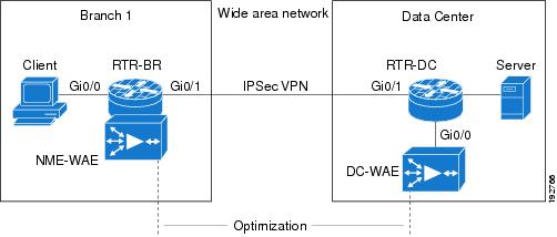
Note ![]() NME-WAE is not supported on ASR. Therefore, to support NME-WAE in branch office, the RTR-BR must be an ISR.
NME-WAE is not supported on ASR. Therefore, to support NME-WAE in branch office, the RTR-BR must be an ISR.
WAAS Branch Deployment with an Off-Path Device
A WAE device can be either an NME-WAE that is installed on an ISR as an integrated service engine (as shown in Figure 3) or a standalone WAE device.
Figure 4 shows a WAAS branch deployment that uses WCCP to redirect traffic to an off-path, standalone WAE device for traffic interception. The configuration for this option is the same as the WAAS branch deployment with an NME-WAE.
Figure 4 WAAS Off-Path Branch Deployment
Note ![]() The RTR-BR (as shown in Figure 4) can be an Aggregation Services Router (ASR).
The RTR-BR (as shown in Figure 4) can be an Aggregation Services Router (ASR).
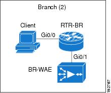
WAAS Branch Deployment with an Inline Device
Figure 5 shows a WAAS branch deployment that has an inline WAE device that is physically in front of the ISR router. Because the WAE device is in front of the router, Layer 7 inspection on the client side is not supported because the Cisco IOS XE firewall receives WAAS optimized packets.
Figure 5 WAAS Inline Path Branch Deployment
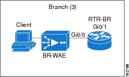
An edge WAAS device with the Cisco IOS XE firewall is applied at branch office sites that must inspect traffic moving to and from a WAN connection. The Cisco IOS XE firewall monitors traffic for optimization indicators (TCP options and subsequent TCP sequence number changes) and allows optimized traffic to pass, while still applying Layer 4 stateful inspection and deep packet inspection to all traffic, maintaining security while accommodating WAAS optimization advantages.
Note ![]() If the WAE device is in the inline location, the device enters its bypass mode after the automatic discovery process. Although the router is not directly involved in WAAS optimization, the router must be aware that WAAS optimization is applied to the traffic in order to apply the Cisco IOS XE firewall inspection to network traffic and make allowances for optimization activity if optimization indicators are present.
If the WAE device is in the inline location, the device enters its bypass mode after the automatic discovery process. Although the router is not directly involved in WAAS optimization, the router must be aware that WAAS optimization is applied to the traffic in order to apply the Cisco IOS XE firewall inspection to network traffic and make allowances for optimization activity if optimization indicators are present.
How to Configure Zone-Based Policy Firewall
•![]() Configuring Layer 3 and Layer 4 Firewall Policies
Configuring Layer 3 and Layer 4 Firewall Policies
•![]() Configuring an Inspect Parameter Map
Configuring an Inspect Parameter Map
•![]() Configuring NetFlow Event Logging
Configuring NetFlow Event Logging
•![]() Creating Security Zones and Zone Pairs, and Attaching a Policy Map to a Zone Pair
Creating Security Zones and Zone Pairs, and Attaching a Policy Map to a Zone Pair
•![]() Configuring the Firewall with WAAS
Configuring the Firewall with WAAS
•![]() Configuring an LDAP-Enabled Firewall
Configuring an LDAP-Enabled Firewall
Configuring Layer 3 and Layer 4 Firewall Policies
Layer 3 and Layer 4 policies are "top level" policies that are attached to the target (zone pair). Use the following tasks to configure Layer 3 and Layer 4 firewall policies:
•![]() Configuring a Class Map for a Layer 3 and Layer 4 Firewall Policy
Configuring a Class Map for a Layer 3 and Layer 4 Firewall Policy
•![]() Creating a Policy Map for a Layer 3 and Layer 4 Firewall Policy
Creating a Policy Map for a Layer 3 and Layer 4 Firewall Policy
Configuring a Class Map for a Layer 3 and Layer 4 Firewall Policy
Perform the following task to configure a class map for classifying network traffic.
Note ![]() You must perform at least one step from Step 4, 5, or 6.
You must perform at least one step from Step 4, 5, or 6.
SUMMARY STEPS
1. ![]() enable
enable
2. ![]() configure terminal
configure terminal
3. ![]() class-map type inspect [match-any | match-all] class-map-name
class-map type inspect [match-any | match-all] class-map-name
4. ![]() match access-group {access-group | name access-group-name}
match access-group {access-group | name access-group-name}
5. ![]() match protocol protocol-name
match protocol protocol-name
6. ![]() exit
exit
Creating a Policy Map for a Layer 3 and Layer 4 Firewall Policy
Perform the following task to create a policy map for a Layer 3 and Layer 4 firewall policy that will be attached to zone pairs.
If you are creating an inspect type policy map, note that only the following actions are allowed: drop, inspect, and pass.
Note ![]() You must perform at least one step from Step 5, 6, or 7.
You must perform at least one step from Step 5, 6, or 7.
SUMMARY STEPS
1. ![]() enable
enable
2. ![]() configure terminal
configure terminal
3. ![]() policy-map type inspect policy-map-name
policy-map type inspect policy-map-name
4. ![]() class type inspect class-name
class type inspect class-name
5. ![]() inspect [parameter-map-name]
inspect [parameter-map-name]
6. ![]() drop [log]
drop [log]
7. ![]() pass [log]
pass [log]
8. ![]() end
end
Configuring an Inspect Parameter Map
An inspect parameter map is optional if you are using an inspect type policy. If you do not configure a parameter map, the software uses default parameters. Parameters associated with the inspect action apply to all nested actions (if any). If parameters are specified in both the top and lower levels, those in the lower levels override those in the top levels
Changes to the parameter map are not reflected on connections already established through the firewall. Changes are applicable only to new connections permitted to the firewall. To ensure that your firewall enforces policies strictly, clear all the connections allowed in the firewall after you change the parameter map. To clear existing connections, use the clear zone-pair inspect sessions command.
SUMMARY STEPS
1. ![]() enable
enable
2. ![]() configure terminal
configure terminal
3. ![]() parameter-map type inspect parameter-map-name
parameter-map type inspect parameter-map-name
4. ![]() alert {on | off}
alert {on | off}
5. ![]() audit-trail {on | off}
audit-trail {on | off}
6. ![]() dns-timeout seconds
dns-timeout seconds
7. ![]() icmp idle-time seconds
icmp idle-time seconds
8. ![]() max-incomplete {low | high} number-of-connections
max-incomplete {low | high} number-of-connections
9. ![]() one-minute {low | high} number-of-connections
one-minute {low | high} number-of-connections
10. ![]() sessions maximum sessions
sessions maximum sessions
11. ![]() tcp finwait-time seconds
tcp finwait-time seconds
12. ![]() tcp idle-time seconds
tcp idle-time seconds
13. ![]() tcp max-incomplete host threshold [block-time minutes]
tcp max-incomplete host threshold [block-time minutes]
14. ![]() tcp synwait-time seconds
tcp synwait-time seconds
15. ![]() udp idle-time seconds
udp idle-time seconds
16. ![]() exit
exit
Configuring NetFlow Event Logging
Global parameter maps are used for NetFlow event logging. With NetFlow event logging enabled, logs are sent to an off-box high-speed log collector. By default, this functionality is not enabled. (If this functionality is not enabled, firewall logs are sent to a logger buffer located in the Route Processor or console.)
SUMMARY STEPS
1. ![]() enable
enable
2. ![]() configure terminal
configure terminal
3. ![]() parameter-map type inspect global
parameter-map type inspect global
4. ![]() log dropped-packets
log dropped-packets
5. ![]() log flow-export v9 udp destination ipv4-address port
log flow-export v9 udp destination ipv4-address port
6. ![]() log flow-export template timeout-rate seconds
log flow-export template timeout-rate seconds
7. ![]() end
end
8. ![]() show parameter-map type inspect global
show parameter-map type inspect global
Creating Security Zones and Zone Pairs, and Attaching a Policy Map to a Zone Pair
You need two security zones to create a zone pair. However, you can create only one security zone and use a system-defined security zone called "self." Note that if you select a self zone, you cannot configure inspect policing. An inspect policy can be present between a zone-self or self-zone zone pair.
Use this process to complete the following tasks:
•![]() Create at least one security zone
Create at least one security zone
•![]() Define zone pairs
Define zone pairs
•![]() Assign interfaces to security zones
Assign interfaces to security zones
•![]() Attach a policy map to a zone pair
Attach a policy map to a zone pair

Tip ![]() Before you create zones, think about what should constitute the zones. The general guideline is that you should group interfaces that are similar when they are viewed from a security perspective.
Before you create zones, think about what should constitute the zones. The general guideline is that you should group interfaces that are similar when they are viewed from a security perspective.
Security Zone Restrictions
•![]() An interface can be a member of only one security zone.
An interface can be a member of only one security zone.
•![]() When an interface is a member of a security zone, all traffic to and from that interface is blocked unless you configure an explicit interzone policy on a zone pair involving that zone.
When an interface is a member of a security zone, all traffic to and from that interface is blocked unless you configure an explicit interzone policy on a zone pair involving that zone.
•![]() Traffic cannot flow between an interface that is a member of a security zone and an interface that is not a member of a security zone because a policy can be applied only between two zones.
Traffic cannot flow between an interface that is a member of a security zone and an interface that is not a member of a security zone because a policy can be applied only between two zones.
•![]() For traffic to flow among all the interfaces in a router, all the interfaces must be members of one security zone or another. This is particularly important because after you make an interface a member of a security zone, a policy action (such as inspect or pass) must explicitly allow packets. Otherwise, packets are dropped.
For traffic to flow among all the interfaces in a router, all the interfaces must be members of one security zone or another. This is particularly important because after you make an interface a member of a security zone, a policy action (such as inspect or pass) must explicitly allow packets. Otherwise, packets are dropped.
•![]() If an interface on a router cannot be part of a security zone or firewall policy, you may have to put that interface in a security zone and configure a "pass all" policy (that is, a "dummy" policy) between that zone and other zones to which a traffic flow is desired.
If an interface on a router cannot be part of a security zone or firewall policy, you may have to put that interface in a security zone and configure a "pass all" policy (that is, a "dummy" policy) between that zone and other zones to which a traffic flow is desired.
•![]() An ACL on an interface that is a zone member should not be restrictive (strict).
An ACL on an interface that is a zone member should not be restrictive (strict).
•![]() Traffic between interfaces in the same security zone is not subjected to any policy; the traffic passes freely. If you have created only one zone, you can use the system-defined default zone (self) as part of a zone pair. Such a zone pair and its associated policy applies to the traffic directed to the router or generated by the router.
Traffic between interfaces in the same security zone is not subjected to any policy; the traffic passes freely. If you have created only one zone, you can use the system-defined default zone (self) as part of a zone pair. Such a zone pair and its associated policy applies to the traffic directed to the router or generated by the router.
•![]() You can use the default keyword to include all the interfaces that are not configured on any of the security zones. In the default zone, the policy can be defined either as a source zone or a destination zone.
You can use the default keyword to include all the interfaces that are not configured on any of the security zones. In the default zone, the policy can be defined either as a source zone or a destination zone.
SUMMARY STEPS
1. ![]() enable
enable
2. ![]() configure terminal
configure terminal
3. ![]() zone security {zone-name | default}
zone security {zone-name | default}
4. ![]() description line-of-description
description line-of-description
5. ![]() exit
exit
6. ![]() zone-pair security zone-pair-name [source {source-zone-name | self | default} destination [destination-zone-name | self | default]]
zone-pair security zone-pair-name [source {source-zone-name | self | default} destination [destination-zone-name | self | default]]
7. ![]() description line-of-description
description line-of-description
8. ![]() service-policy type inspect policy-map-name
service-policy type inspect policy-map-name
9. ![]() exit
exit
10. ![]() interface type number
interface type number
11. ![]() zone-member security zone-name
zone-member security zone-name
12. ![]() exit
exit
Configuring the Firewall with WAAS
Perform the following task to configure an end-to-end WAAS traffic flow optimization for the firewall that uses WCCP to redirect traffic to a WAE device for traffic interception.
In Cisco IOS XE software, WAAS support is always enabled and WAAS processing is always discovered. Thus, the ip inspect waas enable command is not necessary and therefore not supported.
SUMMARY STEPS
1. ![]() enable
enable
2. ![]() configure terminal
configure terminal
3. ![]() ip wccp service-id
ip wccp service-id
4. ![]() class-map type inspect [match-any | match-all] class-map-name
class-map type inspect [match-any | match-all] class-map-name
5. ![]() match protocol protocol-name
match protocol protocol-name
6. ![]() exit
exit
7. ![]() policy-map type inspect policy-map-name
policy-map type inspect policy-map-name
8. ![]() class type inspect class-name
class type inspect class-name
9. ![]() inspect
inspect
10. ![]() class class-default
class class-default
11. ![]() exit
exit
12. ![]() exit
exit
13. ![]() zone security {zone-name | default}
zone security {zone-name | default}
14. ![]() description line-of-description
description line-of-description
15. ![]() exit
exit
16. ![]() zone-pair security zone-pair-name [source {source-zone-name | self | default} destination {destination-zone-name | self | default}]
zone-pair security zone-pair-name [source {source-zone-name | self | default} destination {destination-zone-name | self | default}]
17. ![]() description line-of-description
description line-of-description
18. ![]() service-policy type inspect policy-map-name
service-policy type inspect policy-map-name
19. ![]() exit
exit
20. ![]() interface type number
interface type number
21. ![]() description line-of-description
description line-of-description
22. ![]() zone-member security zone-name
zone-member security zone-name
23. ![]() ip address ip-address mask
ip address ip-address mask
24. ![]() ip wccp {service-id {group-listen | redirect {in | out}} | redirect exclude in | web-cache {group-listen | redirect {in | out}}}
ip wccp {service-id {group-listen | redirect {in | out}} | redirect exclude in | web-cache {group-listen | redirect {in | out}}}
25. ![]() exit
exit
Configuring an LDAP-Enabled Firewall
Lightweight Directory Access Protocol (LDAP) is an application protocol that is used for querying and updating information stored on directory servers. The LDAP-Enabled Firewall feature enables Cisco firewalls to support Layer 4 LDAP inspection by default. Perform the following task to configure an LDAP-enabled firewall.
Prerequisites
You can configure an LDAP-enabled firewall in interface configuration mode or in global configuration mode. Before you configure an LDAP-enabled firewall in interface configuration mode, you must have configured a zone using the zone security command.
SUMMARY STEPS
1. ![]() enable
enable
2. ![]() configure terminal
configure terminal
3. ![]() zone security {zone-name | default}
zone security {zone-name | default}
4. ![]() exit
exit
5. ![]() zone security {zone-name | default}
zone security {zone-name | default}
6. ![]() exit
exit
7. ![]() class-map type inspect [match-any | match-all] class-map-name
class-map type inspect [match-any | match-all] class-map-name
8. ![]() match protocol protocol-name
match protocol protocol-name
9. ![]() exit
exit
10. ![]() policy-map type inspect policy-map-name
policy-map type inspect policy-map-name
11. ![]() class type inspect class-name
class type inspect class-name
12. ![]() inspect
inspect
13. ![]() class class-default
class class-default
14. ![]() exit
exit
15. ![]() exit
exit
16. ![]() zone-pair security zone-pair-name [source {source-zone-name | self | default} destination {destination-zone-name | self | default}]
zone-pair security zone-pair-name [source {source-zone-name | self | default} destination {destination-zone-name | self | default}]
17. ![]() service-policy type inspect policy-map-name
service-policy type inspect policy-map-name
18. ![]() end
end
Configuring an SCCP-Enabled Firewall
SCCP enables voice communication between two Skinny clients through the use of a Cisco Unified Call Manager. The SCCP-Enabled Firewall feature enables Cisco firewalls to inspect Skinny control packets that are exchanged between a Skinny client and the Call Manager. Perform the following task to configure an SCCP-enabled firewall.
Prerequisites
When you enable SCCP (through the match protocol command) in a firewall configuration, you must also enable TFTP (through the match protocol command); otherwise, the IP phones that use SCCP cannot communicate with the Cisco Unified Call Manager.
SUMMARY STEPS
1. ![]() enable
enable
2. ![]() configure terminal
configure terminal
3. ![]() class-map type inspect [match-any | match-all] class-map-name
class-map type inspect [match-any | match-all] class-map-name
4. ![]() match protocol protocol-name
match protocol protocol-name
5. ![]() match protocol protocol-name
match protocol protocol-name
6. ![]() exit
exit
7. ![]() policy-map type inspect match-any policy-map-name
policy-map type inspect match-any policy-map-name
8. ![]() class type inspect class-name
class type inspect class-name
9. ![]() inspect
inspect
10. ![]() class class-default
class class-default
11. ![]() exit
exit
12. ![]() exit
exit
13. ![]() zone security {zone-name | default}
zone security {zone-name | default}
14. ![]() exit
exit
15. ![]() zone security {zone-name | default}
zone security {zone-name | default}
16. ![]() exit
exit
17. ![]() zone-pair security zone-pair-name [source {source-zone-name | self | default} destination {destination-zone-name | self | default}]
zone-pair security zone-pair-name [source {source-zone-name | self | default} destination {destination-zone-name | self | default}]
18. ![]() service-policy type inspect policy-map-name
service-policy type inspect policy-map-name
19. ![]() exit
exit
20. ![]() interface type number
interface type number
21. ![]() zone-member security zone-name
zone-member security zone-name
22. ![]() interface type number
interface type number
23. ![]() zone-member security zone-name
zone-member security zone-name
24. ![]() exit
exit
Configuration Examples for Zone-Based Policy Firewall
•![]() Example: Configuring a Policy-Map and Zone-Based Firewall
Example: Configuring a Policy-Map and Zone-Based Firewall
•![]() Example: Firewall Configuration with WAAS
Example: Firewall Configuration with WAAS
•![]() Example: LDAP-Enabled Firewall Configuration
Example: LDAP-Enabled Firewall Configuration
•![]() Example: SCCP-Enabled Firewall Configuration
Example: SCCP-Enabled Firewall Configuration
Example: Configuring a Policy-Map and Zone-Based Firewall
The following example shows how to configure a policy map and allow TCP flows to pass from the private to public firewall zones:
class-map type inspect match-all no-http-inspect
match access-group 199
match protocol tcp
policy-map type inspect no-http-inspect
class type inspect no-http-inspect
inspect
class class-default
!
zone security private
zone security public
zone-pair security zp source private destination public
service-policy type inspect test
!
interface GigabitEthernet 0/1/0.1
encapsulation dot1Q 2
ip address 10.1.1.1 255.255.255.0
zone-member security private
!
interface GigabitEthernet 0/1/0.2
encapsulation dot1Q 3
ip address 10.2.1.1 255.255.255.0
zone-member security private
!
interface GigabitEthernet 0/1/1.1
encapsulation dot1Q 2
ip address 10.1.1.1 255.255.255.0
zone-member security public
!
interface GigabitEthernet 0/1/1.2
encapsulation dot1Q 3
ip address 10.2.1.1 255.255.255.0
zone-member security public
!
Example: Firewall Configuration with WAAS
The following example provides an end-to-end WAAS traffic flow optimization configuration for the firewall that uses WCCP to redirect traffic to a WAE device for traffic interception.
The following configuration example prevents traffic from being dropped between security zone members because the integrated-service-engine interface is configured on a different zone and each security zone member is assigned an interface.
ip wccp 61
ip wccp 62
class-map type inspect match-any most-traffic
match protocol icmp
match protocol ftp
match protocol tcp
match protocol udp
policy—map type inspect p1
class type inspect most—traffic
inspect
class class—default
zone security zone-hr
zone security zone-outside
zone security z-waas
zone—pair security hr—out source zone-hr destination zone-outside
 service—policy type inspect p1
zone—pair security out—hr source zone-outside destination zone-hr
service—policy type inspect p1
zone—pair security eng—out source zone-eng destination zone-outside
service—policy type inspect p1
interface GigabitEthernet 0/0/0
description Trusted Interface
ipaddress 10.70.0.1 255.0.0.0
ip wccp 61 redirect in
zone—member security zone-hr
interface GigabitEthernet 0/0/1
description Trusted Interface
ipaddress 10.71.0.2 255.0.0.0
ip wccp 61 redirect in
zone—member security zone-eng
interface GigabitEthernet 0/0/1
description Untrusted Interface
ipaddress 10.72.2.3 255.0.0.0
ip wccp 62 redirect in
zone—member security zone-outside
interface Integrated—Service—Engine l/0
ipaddress 10.70.100.1 255.0.0.0
ip wccp redirect exclude in
zone—member security z-waas
Example: LDAP-Enabled Firewall Configuration
The following example shows how to configure a firewall policy to inspect Layer 4 LDAP messages:
Interface Configuration
interface GigabitEthernet 0/1/5
ip address 192.168.0.1 255.255.255.0
zone-member security private
no shutdown
interface GigabitEthernet 0/1/6
ip address 192.168.1.1 255.255.255.0
zone-member security internet
no shutdown
Global Firewall Configuration
zone security private
zone security internet
class-map type inspect match-any internet-traffic-class
match protocol ldap
match protocol ldaps
match protocol ldap-admin
policy-map type inspect private-internet-policy
class type inspect internet-traffic-class
inspect
class class-default
zone-pair security private-internet source private destination internet
service-policy type inspect private-internet-policy
Example: SCCP-Enabled Firewall Configuration
The following example shows how to enable SCCP in a firewall configuration:
class-map type inspect match-any c-appl
match protocol sccp
match protocol tftp
policy-map type inspect p1
class type inspect c-appl
inspect
class class-default
zone security z-in
zone security z-out
zone-pair security in2out source z-in destination z-out
service-policy type inspect p1
interface gigabitethernet 0/1/5
zone-member security z-in
interface gigabitethernet 0/1/
zone-member security z-out
Additional References
Related Documents
|
|
|
|---|---|
Cisco IOS commands |
|
Security commands |
|
Quality of Service commands |
Standards
|
|
|
|---|---|
No new or modified standards are supported by this release. |
— |
MIBs
|
|
|
|---|---|
None |
To locate and download MIBs for selected platforms, Cisco software releases, and feature sets, use Cisco MIB Locator found at the following URL: |
RFCs
|
|
|
|---|---|
RFC 4511 |
Lightweight Directory Access Protocol (LDAP): The Protocol |
Technical Assistance
Feature Information for Zone-Based Policy Firewall
Table 1 lists the features in this module and provides links to specific configuration information.
Use Cisco Feature Navigator to find information about platform support and software image support. Cisco Feature Navigator enables you to determine which software images support a specific software release, feature set, or platform. To access Cisco Feature Navigator, go to http://www.cisco.com/go/cfn. An account on Cisco.com is not required.
Note ![]() Table 1 lists only the software release that introduced support for a given feature in a given software release train. Unless noted otherwise, subsequent releases of that software release train also support that feature.
Table 1 lists only the software release that introduced support for a given feature in a given software release train. Unless noted otherwise, subsequent releases of that software release train also support that feature.
|
|
|
|
|---|---|---|
Firewall—NetMeeting Directory (LDAP) ALG Support |
Cisco IOS XE Release 2.4 |
LDAP is an application protocol that is used for querying and updating information stored on directory servers. This feature enables Cisco Firewalls to support Layer 4 LDAP inspection by default. The following section provides information about this feature: • • The following command was modified: match protocol. |
Firewall—SCCP Video ALG Support |
Cisco IOS XE Release 2.4 |
SCCP enables voice communication between two Skinny clients through the use of a Cisco Unified Call Manager. This feature enables Cisco firewalls to inspect Skinny control packets that are exchanged between a Skinny client and the Call Manager. The following section provides information about this feature: • • The following command was modified: match protocol. |
NAT High Speed Logging (HSL) Support |
Cisco IOS XE Release 2.1 |
This feature introduces support for firewall High Speed Logging (HSL) using NetFlow v9 as the export format. The following section provides information about this feature: • The following commands were introduced to support this feature: log dropped-packet, log flow-export v9 udp destination, log flow-export template timeout-rate, parameter-map type inspect global. |
Zone-Based Policy Firewall |
Cisco IOS XE Release 2.1 |
This feature provides a Cisco IOS XE software unidirectional firewall policy between groups of interfaces known as zones. |
Zone-Based Firewall—Default zone |
Cisco IOS XE Release 2.6 |
A default zone enables a firewall policy to be configured on a zone pair that consist of a zone and a default zone. Any interface without explicit zone membership belongs to a default zone. The following commands were modified: zone-pair security and zone security. |
 Feedback