- Pseudowire Emulation Edge-to-Edge MIBs for Ethernet, Frame Relay, and ATM Services
- MPLS Embedded Management�LSP Ping/Traceroute and AToM VCCV
- MPLS EM�MPLS LSP Multipath Tree Trace
- MPLS Enhancements to Interfaces MIB
- MPLS Label Distribution Protocol MIB
- MPLS Label Distribution Protocol MIB Version 8 Upgrade
- MPLS LSP Ping/Traceroute for LDP/TE, and LSP Ping for VCCV
- MPLS Traffic Engineering�Fast Reroute MIB
- MPLS Traffic Engineering MIB
- MPLS VPN�MIB Support
MPLS: Embedded Management and MIBs Configuration Guide, Cisco IOS XE Release 3S
Bias-Free Language
The documentation set for this product strives to use bias-free language. For the purposes of this documentation set, bias-free is defined as language that does not imply discrimination based on age, disability, gender, racial identity, ethnic identity, sexual orientation, socioeconomic status, and intersectionality. Exceptions may be present in the documentation due to language that is hardcoded in the user interfaces of the product software, language used based on RFP documentation, or language that is used by a referenced third-party product. Learn more about how Cisco is using Inclusive Language.
- Updated:
- February 26, 2009
Chapter: MPLS Embedded Management—LSP Ping/Traceroute and AToM VCCV
- Finding Feature Information
- Contents
- Prerequisites for MPLS Embedded Management—LSP Ping/Traceroute and AToM VCCV
- Restrictions for MPLS Embedded Management—LSP Ping/Traceroute and AToM VCCV
- Information About MPLS Embedded Management—LSP Ping/Traceroute and AToM VCCV
- MPLS LSP Ping Operation
- MPLS LSP Traceroute Operation
- Any Transport over MPLS Virtual Circuit Connection Verification
- MPLS LSP Ping/Traceroute Command Options
- MPLS Echo Request Packets Not Forwarded by IP
- Information Provided by the Router Processing LSP Ping or LSP Traceroute
- MTU Discovery in an LSP
- LSP Network Management
- ICMP ping and trace Commands and Troubleshooting
- Load Balancing for IPv4 LDP LSPs
- Additional References
- Feature Information for MPLS Embedded Management—LSP Ping/Traceroute and AToM VCCV
- Glossary
MPLS Embedded Management-LSP Ping, Traceroute and AToM VCCV
As Multiprotocol Label Switching (MPLS) deployments increase and the traffic types they carry increase, the ability of service providers to monitor label switched paths (LSPs) and quickly isolate MPLS forwarding problems is critical to their ability to offer services. The MPLS Embedded Management—LSP Ping/Traceroute and Any Transport over MPLS Virtual Circuit Connection Verification feature helps them do this.
The MPLS Embedded Management—LSP Ping/Traceroute and AToM VCCV feature can detect when an LSP fails to deliver user traffic.
•![]() You can use MPLS LSP Ping to test LSP connectivity for IPv4 Label Distribution Protocol (LDP) prefixes, traffic engineering (TE) Forwarding Equivalence Classes (FECs), and AToM FECs.
You can use MPLS LSP Ping to test LSP connectivity for IPv4 Label Distribution Protocol (LDP) prefixes, traffic engineering (TE) Forwarding Equivalence Classes (FECs), and AToM FECs.
•![]() You can use MPLS LSP Traceroute to trace the LSPs for IPv4 LDP prefixes and TE tunnel FECs.
You can use MPLS LSP Traceroute to trace the LSPs for IPv4 LDP prefixes and TE tunnel FECs.
•![]() AToM VCCV allows you to use MPLS LSP Ping to test the pseudowire (PW) section of an AToM virtual circuit (VC).
AToM VCCV allows you to use MPLS LSP Ping to test the pseudowire (PW) section of an AToM virtual circuit (VC).
Internet Control Message Protocol (ICMP) ping and trace are often used to help diagnose the root cause when a forwarding failure occurs. The MPLS Embedded Management—LSP Ping/Traceroute and AToM VCCV feature extends this diagnostic and troubleshooting ability to the MPLS network and aids in the identification of inconsistencies between the IP and MPLS forwarding tables, inconsistencies in the MPLS control and data plane, and problems with the reply path.
The MPLS Embedded Management—LSP Ping/Traceroute and AToM VCCV feature uses MPLS echo request and reply packets to test LSPs. The Cisco implementation of MPLS echo request and echo reply are based on the Internet Engineering Task Force (IETF) Internet-Draft Detecting MPLS Data Plane.
Finding Feature Information
For the latest feature information and caveats, see the release notes for your platform and software release. To find information about the features documented in this module, and to see a list of the releases in which each feature is supported, use the "Feature Information for MPLS Embedded Management—LSP Ping/Traceroute and AToM VCCV" section.
Use Cisco Feature Navigator to find information about platform support and Cisco IOS XE software image support. To access Cisco Feature Navigator, go to http://www.cisco.com/go/cfn. An account on Cisco.com is not required.
Contents
•![]() Prerequisites for MPLS Embedded Management—LSP Ping/Traceroute and AToM VCCV
Prerequisites for MPLS Embedded Management—LSP Ping/Traceroute and AToM VCCV
•![]() Restrictions for MPLS Embedded Management—LSP Ping/Traceroute and AToM VCCV
Restrictions for MPLS Embedded Management—LSP Ping/Traceroute and AToM VCCV
•![]() Information About MPLS Embedded Management—LSP Ping/Traceroute and AToM VCCV
Information About MPLS Embedded Management—LSP Ping/Traceroute and AToM VCCV
•![]() Feature Information for MPLS Embedded Management—LSP Ping/Traceroute and AToM VCCV
Feature Information for MPLS Embedded Management—LSP Ping/Traceroute and AToM VCCV
Prerequisites for MPLS Embedded Management—LSP Ping/Traceroute and AToM VCCV
Before you use the MPLS Embedded Management—LSP Ping/Traceroute and AToM VCCV feature, you should:
•![]() Determine the baseline behavior of your MPLS network. For example:
Determine the baseline behavior of your MPLS network. For example:
–![]() What is the expected MPLS experimental (EXP) treatment?
What is the expected MPLS experimental (EXP) treatment?
–![]() What is the expected maximum size packet or maximum transmission unit (MTU) of the label switched path?
What is the expected maximum size packet or maximum transmission unit (MTU) of the label switched path?
–![]() What is the topology? What are the expected label switched paths? How many links in the LSP? Trace the paths of the label switched packets including the paths for load balancing.
What is the topology? What are the expected label switched paths? How many links in the LSP? Trace the paths of the label switched packets including the paths for load balancing.
•![]() Understand how to use MPLS and MPLS applications, including traffic engineering, AToM, and LDP. You need to
Understand how to use MPLS and MPLS applications, including traffic engineering, AToM, and LDP. You need to
–![]() Know how LDP is configured
Know how LDP is configured
–![]() Understand AToM concepts
Understand AToM concepts
–![]() Be able to troubleshoot a TE tunnel
Be able to troubleshoot a TE tunnel
•![]() Understand label switching, forwarding, and load balancing.
Understand label switching, forwarding, and load balancing.
Restrictions for MPLS Embedded Management—LSP Ping/Traceroute and AToM VCCV
The following restrictions apply to the MPLS Embedded Management—LSP Ping/Traceroute and AToM VCCV feature:
•![]() You cannot use MPLS LSP Traceroute to trace the path taken by AToM packets. MPLS LSP Traceroute is not supported for AToM. (MPLS LSP Ping is supported for AToM.) However, you can use MPLS LSP Traceroute to troubleshoot the Interior Gateway Protocol (IGP) LSP that is used by AToM.
You cannot use MPLS LSP Traceroute to trace the path taken by AToM packets. MPLS LSP Traceroute is not supported for AToM. (MPLS LSP Ping is supported for AToM.) However, you can use MPLS LSP Traceroute to troubleshoot the Interior Gateway Protocol (IGP) LSP that is used by AToM.
•![]() You cannot use MPLS LSP Ping/Traceroute to validate/trace MPLS Virtual Private Networks (VPNs).
You cannot use MPLS LSP Ping/Traceroute to validate/trace MPLS Virtual Private Networks (VPNs).
•![]() You cannot use MPLS LSP Traceroute to troubleshoot LSPs that employ Time to Live (TTL) hiding.
You cannot use MPLS LSP Traceroute to troubleshoot LSPs that employ Time to Live (TTL) hiding.
Information About MPLS Embedded Management—LSP Ping/Traceroute and AToM VCCV
Before using the MPLS Embedded Management—LSP Ping/Traceroute and AToM VCCV feature, you need an understanding of the following concepts:
•![]() MPLS LSP Traceroute Operation
MPLS LSP Traceroute Operation
•![]() Any Transport over MPLS Virtual Circuit Connection Verification
Any Transport over MPLS Virtual Circuit Connection Verification
•![]() MPLS LSP Ping/Traceroute Command Options
MPLS LSP Ping/Traceroute Command Options
•![]() MPLS Echo Request Packets Not Forwarded by IP
MPLS Echo Request Packets Not Forwarded by IP
•![]() Information Provided by the Router Processing LSP Ping or LSP Traceroute
Information Provided by the Router Processing LSP Ping or LSP Traceroute
•![]() ICMP ping and trace Commands and Troubleshooting
ICMP ping and trace Commands and Troubleshooting
•![]() Load Balancing for IPv4 LDP LSPs
Load Balancing for IPv4 LDP LSPs
MPLS LSP Ping Operation
MPLS LSP Ping uses MPLS echo request and reply packets to validate an LSP. Both an MPLS echo request and an MPLS echo reply are User Datagram Protocol (UDP) packets with source and destination ports set to 3503.
The MPLS echo request packet is sent to a target router through the use of the appropriate label stack associated with the LSP to be validated. Use of the label stack causes the packet to be switched inband of the LSP (that is, forwarded over the LSP itself). The destination IP address of the MPLS echo request packet is different from the address used to select the label stack. The destination address of the UDP packet is defined as a 127.x.y.z/8 address. This prevents the IP packet from being IP switched to its destination if the LSP is broken.
An MPLS echo reply is sent in response to an MPLS echo request. It is sent as an IP packet and forwarded using IP, MPLS, or a combination of both types of switching. The source address of the MPLS echo reply packet is an address from the router generating the echo reply. The destination address is the source address of the router in the MPLS echo request packet.
Figure 1 shows MPLS LSP Ping echo request and echo reply paths.
Figure 1 MPLS LSP Ping Echo Request and Echo Reply Paths

If you initiate an MPLS LSP Ping request at LSR1 to an FEC at LSR6, you get the results shown in Table 1.
|
|
|
|
|---|---|---|
1. |
LSR1 |
Initiates an MPLS LSP Ping request for an FEC at the target router LSR6 and sends an MPLS echo request to LSR2. |
2. |
LSR2 |
Receives and forwards the MPLS echo request packet through transit routers LSR3 and LSR4 to the penultimate router LSR5. |
3. |
LSR5 |
Receives the MPLS echo request, pops the MPLS label, and forwards the packet to LSR6 as an IP packet. |
4. |
LSR6 |
Receives the IP packet, processes the MPLS echo request, and sends an MPLS echo reply to LSR1 through an alternate route. |
5. |
LSR7 to LSR10 |
Receive and forward the MPLS echo reply back toward LSR1, the originating router. |
6. |
LSR1 |
Receives the MPLS echo reply in response to the MPLS echo request. |
You can use MPLS LSP Ping to validate IPv4 LDP, AToM, and IPv4 Resource Reservation Protocol (RSVP) FECs by using appropriate keywords and arguments with the command:
ping mpls {ipv4 destination-address destination-mask | pseudowire ipv4-address vc-id vc-id
| traffic-eng tunnel-interface tunnel-number}
MPLS LSP Traceroute Operation
MPLS LSP Traceroute also uses MPLS echo request and reply packets to validate an LSP. The echo request and echo reply are UDP packets with source and destination ports set to 3503.
The MPLS LSP Traceroute feature uses time-to-live (TTL) settings to force expiration of the TTL along an LSP. MPLS LSP Traceroute incrementally increases the TTL value in its MPLS echo requests (TTL = 1, 2, 3, 4,...) to discover the downstream mapping of each successive hop. The success of the LSP traceroute depends on the transit router processing the MPLS echo request when it receives a labeled packet with a TTL = 1. On Cisco routers, when the TTL expires, the packet is sent to the Route Processor (RP) for processing. The transit router returns an MPLS echo reply containing information about the transit hop in response to the TTL-expired MPLS packet.
Figure 2 shows an MPLS LSP Traceroute example with an LSP from LSR1 to LSR4.
Figure 2 MPLS LSP Traceroute Example

If you enter an LSP traceroute to a FEC at LSR4 from LSR1, you get the results shown in Table 2.
|
|
|
|
|
|---|---|---|---|
1. |
LSR1 |
MPLS echo request—With a target FEC pointing to LSR4 and to a downstream mapping |
• • |
2. |
LSR2 |
MPLS echo reply |
Receives packet with TTL = 1 • • |
3. |
LSR1 |
MPLS echo request—With the same target FEC and the downstream mapping received in the echo reply from LSR2 |
• • |
4. |
LSR2 |
MPLS echo request |
Receives packet with TTL = 2 • • |
5. |
LSR3 |
MPLS reply packet |
Receives packet with TTL = 1 • • |
6. |
LSR1 |
MPLS echo request—With the same target FEC and the downstream mapping received in the echo reply from LSR3 |
• • |
7. |
LSR2 |
MPLS echo request |
Receives packet with TTL = 3 • • |
8. |
LSR3 |
MPLS echo request |
Receives packet with TTL = 2 • • |
9. |
LSR4 |
MPLS echo reply |
Receives packet with TTL = 1 • • • |
You can use MPLS LSP Traceroute to validate IPv4 LDP and IPv4 RSVP FECs by using appropriate keywords and arguments with the trace mpls command:
trace mpls {ipv4 destination-address destination-mask | traffic-eng tunnel-interface
tunnel-number}
By default, the TTL is set to 30. Therefore, the traceroute output always contains 30 lines, even if an LSP problem exists. This might mean duplicate entries in the output, should an LSP problem occur. The router address of the last point that the trace reaches is repeated until the ouput is 30 lines. You can ignore the duplicate entries. The following example shows that the trace encountered an LSP problem at the router that has an IP address of 10.6.1.6:
Router# traceroute mpls ipv4 10.6.7.4/32
Tracing MPLS Label Switched Path to 10.6.7.4/32, timeout is 2 seconds
Codes: '!' - success, 'Q' - request not transmitted,
'.' - timeout, 'U' - unreachable,
'R' - downstream router but not target
Type escape sequence to abort.
0 10.6.1.14 MRU 4470 [Labels: 22 Exp: 0]
R 1 10.6.1.5 MRU 4470 [Labels: 21 Exp: 0] 2 ms
R 2 10.6.1.6 4 ms <------ Router address repeated for 2nd to 30th TTL.
R 3 10.6.1.6 1 ms
R 4 10.6.1.6 1 ms
R 5 10.6.1.6 3 ms
R 6 10.6.1.6 4 ms
R 7 10.6.1.6 1 ms
R 8 10.6.1.6 2 ms
R 9 10.6.1.6 3 ms
R 10 10.6.1.6 4 ms
R 11 10.6.1.6 1 ms
R 12 10.6.1.6 2 ms
R 13 10.6.1.6 4 ms
R 14 10.6.1.6 5 ms
R 15 10.6.1.6 2 ms
R 16 10.6.1.6 3 ms
R 17 10.6.1.6 4 ms
R 18 10.6.1.6 2 ms
R 19 10.6.1.6 3 ms
R 20 10.6.1.6 4 ms
R 21 10.6.1.6 1 ms
R 22 10.6.1.6 2 ms
R 23 10.6.1.6 3 ms
R 24 10.6.1.6 4 ms
R 25 10.6.1.6 1 ms
R 26 10.6.1.6 3 ms
R 27 10.6.1.6 4 ms
R 28 10.6.1.6 1 ms
R 29 10.6.1.6 2 ms
R 30 10.6.1.6 3 ms <------ TTL 30.
If you know the maximum number of hops in your network, you can set the TTL to a smaller value with the trace mpls ttl maximum-time-to-live command. The following example shows the same traceroute command as the previous example, except that this time the TTL is set to 5.
Router# traceroute mpls ipv4 10.6.7.4/32 ttl 5
Tracing MPLS Label Switched Path to 10.6.7.4/32, timeout is 2 seconds
Codes: '!' - success, 'Q' - request not transmitted,
'.' - timeout, 'U' - unreachable,
'R' - downstream router but not target
Type escape sequence to abort.
0 10.6.1.14 MRU 4470 [Labels: 22 Exp: 0]
R 1 10.6.1.5 MRU 4474 [No Label] 3 ms
R 2 10.6.1.6 4 ms <------ Router address repeated for 2nd to 5th TTL.
R 3 10.6.1.6 1 ms
R 4 10.6.1.6 3 ms
R 5 10.6.1.6 4 ms
Any Transport over MPLS Virtual Circuit Connection Verification
AToM Virtual Circuit Connection Verification (AToM VCCV) allows the sending of control packets inband of an AToM PW from the originating provider edge (PE) router. The transmission is intercepted at the destination PE router, instead of being forwarded to the customer edge (CE) router. This capability allows you to use MPLS LSP Ping to test the PW section of AToM virtual circuits (VCs).
AToM VCCV consists of the following:
•![]() A signaled component in which the AToM VCCV capabilities are advertised during VC label signaling
A signaled component in which the AToM VCCV capabilities are advertised during VC label signaling
•![]() A switching component that causes the AToM VC payload to be treated as a control packet
A switching component that causes the AToM VC payload to be treated as a control packet
AToM VCCV Signaling
One of the steps involved in AToM VC setup is the signaling of VC labels and AToM VCCV capabilities between AToM VC endpoints. The router uses an optional parameter, defined in the Internet Draft draft-ieft-pwe3-vccv-01.txt, to communicate the AToM VCCV disposition capabilities of each endpoint.
The AToM VCCV disposition capabilities are categorized as follows:
•![]() Applications—MPLS LSP Ping and ICMP Ping are applications that AToM VCCV supports to send packets inband of an AToM PW for control purposes.
Applications—MPLS LSP Ping and ICMP Ping are applications that AToM VCCV supports to send packets inband of an AToM PW for control purposes.
•![]() Switching modes—Type 1 and Type 2 are switching modes that AToM VCCV uses for differentiating between control and data traffic.
Switching modes—Type 1 and Type 2 are switching modes that AToM VCCV uses for differentiating between control and data traffic.
Table 3 describes AToM VCCV Type 1 and Type 2 switching modes.
Selection of AToM VCCV Switching Types
Cisco routers always use Type 1 switching, if available, when they send MPLS LSP Ping packets over an AToM VC control channel. Type 2 switching accommodates those VC types and implementations that do not support or interpret the AToM control word.
Table 4 shows the AToM VCCV switching mode advertised and the switching mode selected by the AToM VC.
An AToM VC advertises its AToM VCCV disposition capabilities in both directions: that is, from the originating router (PE1) to the destination router (PE2), and from PE2 to PE1.
In some instances, AToM VCs might use different switching types if the two endpoints have different AToM VCCV capabilities. If PE1 supports Type 1 and Type 2 AToM VCCV switching and PE2 supports only Type 2 AToM VCCV switching, there are two consequences:
•![]() LSP ping packets sent from PE1 to PE2 are encapsulated with Type 2 switching.
LSP ping packets sent from PE1 to PE2 are encapsulated with Type 2 switching.
•![]() LSP ping packets sent from PE2 to PE1 use Type 1 switching.
LSP ping packets sent from PE2 to PE1 use Type 1 switching.
You can determine the AToM VCCV capabilities advertised to and received from the peer by entering the show mpls l2transport binding command at the PE router. For example:
Router# show mpls l2transport binding
Destination Address: 10.131.191.252, VC ID: 333
Local Label: 16
Cbit: 1, VC Type: FastEthernet, GroupID: 0
MTU: 1500, Interface Desc: n/a
VCCV Capabilities: Type 1, Type 2
Remote Label: 19
Cbit: 1, VC Type: FastEthernet, GroupID: 0
MTU: 1500, Interface Desc: n/a
VCCV Capabilities: Type 1
MPLS LSP Ping/Traceroute Command Options
MPLS LSP Ping/Traceroute command options are specified as keywords and arguments on the ping mpls and trace mpls commands.
The ping mpls command provides the following options:
ping mpls {ipv4 destination-address destination-mask [destination address-start
address-end increment] [ttl time-to-live] | pseudowire ipv4-address vc-id vc-id
[destination address-start address-end increment] | traffic-eng tunnel-interface
tunnel-number [ttl time-to-live]} [source source-address] [repeat count]
[timeout seconds][{size packet-size} | {sweep minimum maximum size-increment}]
[pad pattern] [reply mode reply-mode] [interval msec] [exp exp-bits] [verbose]
The trace mpls command provides the following options:
trace mpls {ipv4 destination-address destination-mask [destination address-start
address-end address-increment] | traffic-eng tunnel-interface tunnel-number}
[source source-address] [timeout seconds] [reply mode reply-mode]
[ttl maximum-time-to-live] [exp exp-bits]
The following sections describe some command options of the MPLS LSP Ping/Traceroute features:
•![]() Selection of FECs for Validation
Selection of FECs for Validation
•![]() Reply Mode Options for MPLS LSP Ping/Traceroute
Reply Mode Options for MPLS LSP Ping/Traceroute
•![]() Other MPLS LSP Ping/Traceroute Command Options
Other MPLS LSP Ping/Traceroute Command Options
•![]() MPLS LSP Ping/Traceroute Option Interactions and Loops
MPLS LSP Ping/Traceroute Option Interactions and Loops
Selection of FECs for Validation
An LSP is formed by labels. Routers learn labels through LDP, TE, AToM, or other MPLS applications. You can use MPLS LSP Ping/Traceroute to validate an LSP used for forwarding traffic for a given FEC. Table 5 lists the keywords and arguments for the ping mpls and traceroute mpls commands that allow the selection of an LSP for validation.
|
|
|
|
|---|---|---|
LDP IPv4 prefix |
ipv4 destination-address destination-mask |
ipv4 destination-address destination-mask |
MPLS TE tunnel |
traffic-eng tunnel-interface tunnel-number |
traffic-eng tunnel-interface tunnel-number |
AToM VC |
pseudowire ipv4-address vc-id vc-id |
—1 |
1 MPLS LSP Traceroute does not support the AToM tunnel LSP type for this release. |
Reply Mode Options for MPLS LSP Ping/Traceroute
The reply mode is used to control how the responding router replies to an MPLS echo request sent by an MPLS LSP Ping or MPLS LSP Traceroute command. Table 6 describes the reply mode options.
The reply with an IPv4 UDP packet implies that the router should send an IPv4 UDP packet in reply to an MPLS echo request. If you select the ipv4 reply mode, you do not have explicit control over whether the packet uses IP or MPLS hops to reach the originator of the MPLS echo request. This is the mode that you would normally use to test and verify LSPs.
The reply with an IPv4 UDP packet that contains a router alert forces the packet to go back to the destination and be processed by the Route Processor (RP) process switching at each intermediate hop. This bypasses hardware/line card forwarding table inconsistencies. You should select this option when the originating (headend) routers fail to receive a reply to the MPLS echo request.
You can instruct the replying router to send an echo reply with the IP router alert option by using one of the following commands:
ping mpls {ipv4 destination-address destination-mask | pseudowire ipv4-address vc-id vc-id
| traffic-eng tunnel-interface tunnel-number} reply mode router-alert
or
trace mpls {ipv4 destination-address destination-mask | traffic-eng tunnel-interface
tunnel-number} reply mode router-alert
However, the reply with a router alert adds overhead to the process of getting a reply back to the originating router. This method is more expensive to process than a reply without a router alert and should be used only if there are reply failures. That is, the reply with a router alert label should only be used for MPLS LSP Ping or MPLS LSP Traceroute when the originating (headend) router fails to receive a reply to an MPLS echo request.
Packet Handling Along Return Path with an IP/MPLS Router Alert
When an IP packet that contains an IP router alert option in its IP header or an MPLS packet with a router alert label as its outermost label arrives at a router, the router punts (redirects) the packet to the RP process level for handling. This allows these packets to bypass the forwarding failures in hardware routing tables. Table 7 describes how IP and MPLS packets with an IP router alert option are handled by the router switching path processes.
Other MPLS LSP Ping/Traceroute Command Options
Table 8 describes other MPLS LSP Ping/Traceroute command options that can be specified as keywords or arguments with the ping mpls command, or with both the ping mpls and trace mpls commands. Options available for you to use only on the ping mpls command are indicated as such.
MPLS LSP Ping options described in Table 8 can be implemented by the use of the following syntax:
ping mpls {ipv4 destination-address destination-mask [destination address-start
address-end increment] [ttl time-to-live] | pseudowire ipv4-address vc-id vc-id
[destination address-start address-end increment] | traffic-eng tunnel-interface
tunnel-number [ttl time-to-live]} [source source-address] [repeat count]
[{size packet-size} | {sweep minimum maximum size-increment}] [pad pattern]
[timeout seconds] [interval msec] [exp exp-bits] [verbose]
MPLS LSP Traceroute options described in Table 8 can be implemented by the use of the following syntax:
trace mpls {ipv4 destination-address destination-mask [destination address-start
address-end address-increment] | traffic-eng tunnel-interface tunnel-number}
[source source-address] [timeout seconds] [ttl maximum-time-to-live] [exp exp-bits]
MPLS LSP Ping/Traceroute Option Interactions and Loops
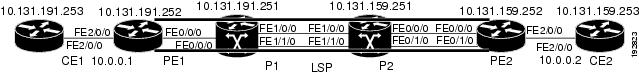
Usage examples for the MPLS Embedded Management—LSP Ping/Traceroute and AToM VCCV feature in this and subsequent sections are based on the sample topology shown in Figure 3.
Figure 3 Sample Topology for Configuration Examples
The interaction of some MPLS Embedded Management—LSP Ping/Traceroute and AToM VCCV options can cause loops. See the following topic for a description of the loops you might encounter with the ping mpls and trace mpls commands:
•![]() Possible Loops with MPLS LSP Ping
Possible Loops with MPLS LSP Ping
•![]() Possible Loop with MPLS LSP Traceroute
Possible Loop with MPLS LSP Traceroute
Possible Loops with MPLS LSP Ping
With the MPLS LSP Ping feature, loops can occur if you use the repeat count option, the sweep size range option, or the UDP destination address range option.
ping mpls {ipv4 destination-address destination-mask [destination address-start
address-end increment] | pseudowire ipv4-address vc-id vc-id [destination address-start
address-end increment] | traffic-eng tunnel-interface tunnel-number} [repeat count]
[sweep minimum maximum size-increment]
Following is an example of how a loop operates if you use the following keywords and arguments on the ping mpls command:
Router# ping mpls ipv4 10.131.159.251/32 destination 127.0.0.1 127.0.0.1 0.0.0.1 repeat 2
sweep 1450 1475 25
Sending 2, [1450..1500]-byte MPLS Echos to 10.131.159.251/32,
timeout is 2 seconds, send interval is 0 msec:
Codes: '!' - success, 'Q' - request not transmitted,
'.' - timeout, 'U' - unreachable,
'R' - downstream router but not target
Type escape sequence to abort.
Destination address 127.0.0.1
!
!
Destination address 127.0.0.1
!
!
Destination address 127.0.0.1
!
!
Destination address 127.0.0.1
!
!
An mpls ping command is sent for each packet size range for each destination address until the end address is reached. For this example, the loop continues in the same manner until the destination address, 127.0.0.1, is reached. The sequence continues until the number is reached that you specified with the repeat count keyword and argument. For this example, the repeat count is 2. The MPLS LSP Ping loop sequence is as follows:
repeat = 1
destination address 1 (address-start)
for (size from sweep minimum to maximum, counting by size-increment)
send an lsp ping
destination address 2 (address-start + address-increment)
for (size from sweep minimum to maximum, counting by size-increment)
send an lsp ping
destination address 3 (address-start + address-increment + address-increment)
for (size from sweep minimum to maximum, counting by size-increment)
send an lsp ping
.
.
.
until destination address = address-end
.
.
.
until repeat = count
Possible Loop with MPLS LSP Traceroute
With the MPLS LSP Traceroute feature, loops can occur if you use the UDP destination address range option and the time-to-live option.
trace mpls {ipv4 destination-address destination-mask [destination address-start
address-end address-increment] | traffic-eng tunnel-interface tunnel-number
[ttl maximum-time-to-live]
Here is an example of how a loop operates if you use the following keywords and arguments on the trace mpls command:
Router# trace mpls ipv4 10.131.159.251/32 destination 127.0.0.1 127.0.0.1 1 ttl 5
Tracing MPLS Label Switched Path to 10.131.159.251/32, timeout is 2 seconds
Codes: '!' - success, 'Q' - request not transmitted,
'.' - timeout, 'U' - unreachable,
'R' - downstream router but not target
Type escape sequence to abort.
Destination address 127.0.0.1
0 10.131.191.230 MRU 1500 [Labels: 19 Exp: 0]
R 1 10.131.159.226 MRU 1504 [implicit-null] 40 ms
! 2 10.131.159.225 40 ms
Destination address 127.0.0.2
0 10.131.191.230 MRU 1500 [Labels: 19 Exp: 0]
R 1 10.131.159.226 MRU 1504 [implicit-null] 40 ms
! 2 10.131.159.225 40 ms
Destination address 127.0.0.3
0 10.131.191.230 MRU 1500 [Labels: 19 Exp: 0]
R 1 10.131.159.226 MRU 1504 [implicit-null] 40 ms
! 2 10.131.159.225 48 ms
An mpls trace command is sent for each TTL from 1 to the maximum TTL (ttl maximum-time-to-live keyword and argument) for each destination address until the address specified with the destination end-address argument is reached. For this example, the maximum TTL is 5 and the end destination address is 127.0.0.1. The MPLS LSP Traceroute loop sequence is as follows:
destination address 1 (address-start)
for (ttl from 1 to maximum-time-to-live)
send an lsp trace
destination address 2 (address-start + address-increment)
for (ttl from 1 to maximum-time-to-live)
send an lsp trace
destination address 3 (address-start + address-increment + address-increment)
for (ttl from 1 to maximum-time-to-live)
send an lsp trace
.
.
.
until destination address = address-end
MPLS Echo Request Packets Not Forwarded by IP
MPLS echo request packets sent during an LSP ping are never forwarded by IP. The IP header destination address field in an MPLS echo request packet is a 127.x.y.z/8 address. Routers should not forward packets using a 127.x.y.z/8 address. The 127.x.y.z/8 address corresponds to an address for the local host.
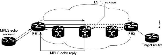
The use of a 127.x.y.z address as a destination address of the UDP packet is significant in that the MPLS echo request packet fails to make it to the target router if a transit router does not label switch the LSP. This allows for the detection of LSP breakages.
•![]() If an LSP breakage occurs at a transit router, the MPLS echo packet is not forwarded, but consumed by the router.
If an LSP breakage occurs at a transit router, the MPLS echo packet is not forwarded, but consumed by the router.
•![]() If the LSP is intact, the MPLS echo packet reaches the target router and is processed by the terminal point of the LSP.
If the LSP is intact, the MPLS echo packet reaches the target router and is processed by the terminal point of the LSP.
Figure 4 shows the path of the MPLS echo request and reply when a transit router fails to label switch a packet in an LSP.
Figure 4 Path When Transit Router Fails to Label Switch a Packet

Note ![]() An AToM payload does not contain usable forwarding information at a transit router because the payload might not be an IP packet. An MPLS VPN packet, although an IP packet, does not contain usable forwarding information at a transit router because the destination IP address is only significant to the VRFs at the endpoints of the MPLS network.
An AToM payload does not contain usable forwarding information at a transit router because the payload might not be an IP packet. An MPLS VPN packet, although an IP packet, does not contain usable forwarding information at a transit router because the destination IP address is only significant to the VRFs at the endpoints of the MPLS network.
Information Provided by the Router Processing LSP Ping or LSP Traceroute
Table 9 describes the characters that the router processing an LSP ping or LSP traceroute packet returns to the sender about the failure or success of the request.
You can also view the return code for an MPLS LSP Ping operation if you enter the verbose keyword on the ping mpls command.
MTU Discovery in an LSP
During an MLPS LSP Ping, MPLS echo request packets are sent with the IP packet attribute set to do not fragment. That is, the DF bit is set in the IP header of the packet. This allows you to use the MPLS echo request to test for the MTU that can be supported for the packet through the LSP without fragmentation.
Figure 5 shows a sample network with a single LSP from PE1 to PE2 formed with labels advertised by means of LDP.
Figure 5 Sample Network with LSP—Labels Advertised by LDP

You can determine the maximum receive unit (MRU) at each hop by tracing the LSP using the MPLS Traceroute feature. The MRU is the maximum size of a labeled packet that can be forwarded through an LSP. The following example shows the results of a trace mpls command when the LSP is formed with labels created by LDP:
Router# trace mpls ipv4 10.131.159.252/32
Tracing MPLS Label Switched Path to 10.131.159.252/32, timeout is 2 seconds
Codes: '!' - success, 'Q' - request not transmitted,
'.' - timeout, 'U' - unreachable,
'R' - downstream router but not target
Type escape sequence to abort.
0 10.131.191.230 MRU 1496 [Labels: 22/19 Exp: 0/0]
R 1 10.131.159.226 MRU 1500 [Labels: 19 Exp: 0] 40 ms
R 2 10.131.159.229 MRU 1504 [implicit-null] 28 ms
! 3 10.131.159.230 40 ms
You can determine the MRU for the LSP at each hop through the use of the show forwarding detail command:
Router# show mpls forwarding 10.131.159.252 detail
Local Outgoing Prefix Bytes tag Outgoing Next Hop
tag tag or VC or Tunnel Id switched interface
22 19 10.131.159.252/32 0 Tu1 point2point
MAC/Encaps=14/22, MRU=1496, Tag Stack{22 19}, via Et0/0
AABBCC009700AABBCC0098008847 0001600000013000
No output feature configured
To determine the maximum sized echo request that will fit on the LSP, you can find the IP MTU by using the show interface interface-name command.
Router# show interface e0/0
FastEthernet0/0/0 is up, line protocol is up
Hardware is Lance, address is aabb.cc00.9800 (bia aabb.cc00.9800)
Internet address is 10.131.191.230/30
MTU 1500 bytes, BW 10000 Kbit, DLY 1000 usec, rely 255/255, load 1/255
Encapsulation ARPA, loopback not set
Keepalive set (10 sec)
ARP type: ARPA, ARP Timeout 04:00:00
Last input 00:00:01, output 00:00:01, output hang never
Last clearing of "show interface" counters never
Input queue: 0/75/0/0 (size/max/drops/flushes); Total output drops: 0
Queueing strategy: fifo
Output queue: 0/40 (size/max)
5 minute input rate 0 bits/sec, 0 packets/sec
5 minute output rate 0 bits/sec, 0 packets/sec
377795 packets input, 33969220 bytes, 0 no buffer
Received 231137 broadcasts, 0 runts, 0 giants, 0 throttles
0 input errors, 0 CRC, 0 frame, 0 overrun, 0 ignored
0 input packets with dribble condition detected
441772 packets output, 40401350 bytes, 0 underruns
0 output errors, 0 collisions, 10 interface resets
0 babbles, 0 late collision, 0 deferred
0 lost carrier, 0 no carrier
0 output buffer failures, 0 output buffers swapped out
The IP MTU in the show interface interface-name example is 1500 bytes. Subtract the number of bytes corresponding to the label stack from the MTU number. From the output of the show mpls forwarding command, the Tag stack consists of one label (21). Therefore, the largest MPLS echo request packet that can be sent in the LSP, shown in Figure 5, is 1500 - (2 x 4) = 1492.
You can validate this by using the following mpls ping command:
Router# ping mpls ipv4 10.131.159.252/32 sweep 1492 1500 1 repeat 1
Sending 1, [1492..1500]-byte MPLS Echos to 10.131.159.252/32,
timeout is 2 seconds, send interval is 0 msec:
Codes: '!' - success, 'Q' - request not transmitted,
'.' - timeout, 'U' - unreachable,
'R' - downstream router but not target
Type escape sequence to abort.
!QQQQQQQQ
Success rate is 11 percent (1/9), round-trip min/avg/max = 40/40/40 ms
In this command, only packets of 1492 bytes are sent successfully, as indicated by the exclamation point (!). Packets of byte sizes 1493 to 1500 are source-quenched, as indicated by the Q.
You can pad an MPLS echo request so that a payload of a given size can be tested. The pad TLV is useful when you use the MPLS echo request to discover the MTU supportable by an LSP. MTU discovery is extremely important for applications like AToM that contain non-IP payloads that cannot be fragmented.
LSP Network Management
To manage an MPLS network you must have the ability to monitor label switched paths (LSPs) and quickly isolate MPLS forwarding problems. You need ways to characterize the liveliness of an LSP and reliably detect when a label switched path fails to deliver user traffic.
You can use MPLS LSP Ping to verify the LSP that is used to transport packets destined for IPv4 LDP prefixes, TE tunnels, and AToM PW FECs. You can use MPLS LSP Traceroute to trace LSPs that are used to carry packets destined for IPv4 LDP prefixes and TE tunnel FECs.
An MPLS echo request is sent through an LSP to validate it. A TTL expiration or LSP breakage causes the transit router to process the echo request before it gets to the intended destination and returns an MPLS echo reply that contains an explanatory reply code to the originator of the echo request.
The successful echo request is processed at the egress of the LSP. The echo reply is sent via an IP path, an MPLS path, or a combination of both back to the originator of the echo request.
ICMP ping and trace Commands and Troubleshooting
ICMP ping and trace commands are often used to help diagnose the root cause of a failure. When an LSP is broken, the packet might make its way to the target router by way of IP forwarding, thus making ICMP ping and traceroute unreliable for detecting MPLS forwarding problems. The MPLS Embedded Management—LSP Ping/Traceroute and AToM VCCV feature extends this diagnostic and troubleshooting ability to the MPLS network and handles inconsistencies between the IP and MPLS forwarding tables, inconsistencies in the MPLS control and data plane, and problems with the reply path.
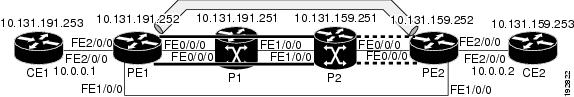
Figure 6 shows a sample topology with an LDP LSP and TE tunnel LSP.
Figure 6 Sample Topology with LDP and TE Tunnel LSPs
This section contains the following topics:
•![]() MPLS LSP Ping/Traceroute Discovers LSP Breakage
MPLS LSP Ping/Traceroute Discovers LSP Breakage
•![]() MPLS LSP Traceroute Tracks Untagged Cases
MPLS LSP Traceroute Tracks Untagged Cases
•![]() MPLS LSP Ping/Traceroute Returns a Q
MPLS LSP Ping/Traceroute Returns a Q
MPLS LSP Ping/Traceroute Discovers LSP Breakage
This section contains the following topics:
•![]() Configuration for Sample Topology
Configuration for Sample Topology
•![]() Verifying That the LSP Is Set Up Correctly
Verifying That the LSP Is Set Up Correctly
Configuration for Sample Topology
These are sample topology configurations for the troubleshooting examples in the following sections (see Figure 6). There are the six sample router configurations.
Router CE1 Configuration
Following is the configuration for the CE1 router:
version 12.0
!
hostname ce1
!
enable password lab
!
interface Loopback0
ip address 10.131.191.253 255.255.255.255
no ip directed-broadcast
!
interface FastEthernet2/0/0
ip address 10.0.0.1 255.255.255.255
no ip directed-broadcast
no keepalive
no cdp enable
!
end
Router PE1 Configuration
Following is the configuration for the PE1 router:
version 12.0
!
hostname pe1
!
ip cef
mpls label protocol ldp
mpls traffic-eng tunnels
no mpls traffic-eng auto-bw timers frequency 0
mpls ldp discovery targeted-hello accept
!
interface Loopback0
ip address 10.131.191.252 255.255.255.255
no ip directed-broadcast
!
interface Tunnel1
ip unnumbered Loopback0
no ip directed-broadcast
mpls label protocol ldp
mpls ip
tunnel destination 10.131.159.255
tunnel mode mpls traffic-eng
tunnel mpls traffic-eng autoroute announce
tunnel mpls traffic-eng priority 2 2
tunnel mpls traffic-eng bandwidth 512
tunnel mpls traffic-eng path-option 1 dynamic
!
interface Tunnel2
ip unnumbered Loopback0
no ip directed-broadcast
shutdown
mpls label protocol ldp
mpls ip
tunnel destination 10.131.159.255
tunnel mode mpls traffic-eng
tunnel mpls traffic-eng autoroute announce
tunnel mpls traffic-eng priority 1 1
tunnel mpls traffic-eng bandwidth 100
tunnel mpls traffic-eng path-option 1 dynamic
!
interface FastEthernet0/0/0
ip address 10.131.191.230 255.255.255.255
no ip directed-broadcast
mpls traffic-eng tunnels
mpls ip
ip rsvp bandwidth 1500 1500
ip rsvp signalling dscp 0
!
interface FastEthernet1/0/0
ip address 10.131.159.246 255.255.255.255
no ip directed-broadcast
no shutdown
mpls ip
ip rsvp bandwidth 1500 1500
ip rsvp signalling dscp 0
!
interface FastEthernet2/0/0
no ip address
no ip directed-broadcast
no cdp enable
xconnect 10.131.159.252 333 encapsulation mpls
!
interface FastEthernet3/0/0
no ip address
no ip directed-broadcast
shutdown
!
router ospf 1
log-adjacency-changes
passive-interface Loopback0
network 10.131.159.244 0.0.0.3 area 0
network 10.131.191.228 0.0.0.3 area 0
network 10.131.191.232 0.0.0.3 area 0
network 10.131.191.252 0.0.0.0 area 0
mpls traffic-eng router-id Loopback0
mpls traffic-eng area 0
!
ip classless
end
Router P1 Configuration
Following is the configuration for the P1 router:
version 12.0
service timestamps debug datetime msec
service timestamps log datetime msec
no service password-encryption
!
hostname p1
!
enable password lab
!
ip cef
mpls label protocol ldp
mpls ldp logging neighbor-changes
mpls traffic-eng tunnels
no mpls traffic-eng auto-bw timers frequency 0
mpls ldp discovery targeted-hello accept
!
interface Loopback0
ip address 10.131.191.251 255.255.255.255
no ip directed-broadcast
!
interface FastEthernet0/0/0
ip address 10.131.191.229 255.255.255.255
no ip directed-broadcast
mpls traffic-eng tunnels
mpls ip
ip rsvp bandwidth 1500 1500
ip rsvp signalling dscp 0
!
interface FastEthernet1/0/0
ip address 10.131.159.226 255.255.255.255
no ip directed-broadcast
mpls traffic-eng tunnels
mpls ip
ip rsvp bandwidth 1500 1500
ip rsvp signalling dscp 0
!
router ospf 1
log-adjacency-changes
passive-interface Loopback0
network 10.131.159.224 0.0.0.3 area 0
network 10.131.191.228 0.0.0.3 area 0
network 10.131.191.251 0.0.0.0 area 0
mpls traffic-eng router-id Loopback0
mpls traffic-eng area 0
!
end
Router P2 Configuration
Following is the configuration for the P2 router:
version 12.0
hostname p2
!
ip cef
mpls label protocol ldp
mpls ldp logging neighbor-changes
mpls traffic-eng tunnels
no mpls traffic-eng auto-bw timers frequency 0
mpls ldp discovery directed-hello accept
!
!
interface Loopback0
ip address 10.131.159.251 255.255.255.255
no ip directed-broadcast
!
interface FastEthernet0/0/0
ip address 10.131.159.229 255.255.255.255
no ip directed-broadcast
mpls traffic-eng tunnels
mpls ip
ip rsvp bandwidth 1500 1500
ip rsvp signalling dscp 0
!
interface FastEthernet1/0/0
ip address 10.131.159.225 255.255.255.255
no ip directed-broadcast
mpls traffic-eng tunnels
mpls ip
ip rsvp bandwidth 1500 1500
ip rsvp signalling dscp 0
!
router ospf 1
log-adjacency-changes
passive-interface Loopback0
network 10.131.159.224 0.0.0.3 area 0
network 10.131.159.228 0.0.0.3 area 0
network 10.131.159.251 0.0.0.0 area 0
mpls traffic-eng router-id Loopback0
mpls traffic-eng area 0
!
end
Router PE2 Configuration
Following is the configuration for the PE2 router:
version 12.0
service timestamps debug datetime msec
service timestamps log datetime msec
no service password-encryption
!
hostname as2_pe
!
logging snmp-authfail
enable password lab
!
clock timezone EST -5
ip subnet-zero
ip cef
no ip domain-lookup
mpls label protocol ldp
mpls ldp logging neighbor-changes
mpls ldp explicit-null
mpls traffic-eng tunnels
no mpls traffic-eng auto-bw timers frequency 0
tag-switching tdp discovery directed-hello accept
frame-relay switching
!
!
interface Loopback0
ip address 10.131.159.252 255.255.255.255
no ip directed-broadcast
!
interface Tunnel0
ip unnumbered Loopback0
no ip directed-broadcast
tunnel destination 10.131.191.252
tunnel mode mpls traffic-eng
tunnel mpls traffic-eng path-option 5 explicit name as1pe-long-path
!
interface FastEthernet0/0/0
ip address 10.131.159.230 255.255.255.255
no ip directed-broadcast
mpls traffic-eng tunnels
tag-switching ip
ip rsvp bandwidth 1500 1500
ip rsvp signalling dscp 0
!
interface FastEthernet1/0/0
ip address 10.131.159.245 255.255.255.255
no ip directed-broadcast
mpls traffic-eng tunnels
tag-switching ip
ip rsvp bandwidth 1500 1500
ip rsvp signalling dscp 0
!
interface FastEthernet2/0/0
no ip address
no ip directed-broadcast
no cdp enable
xconnect 10.131.191.252 333 encapsulation mpls
!
interface FastEthernet3/0/0
no ip address
no ip directed-broadcast
!
interface Serial4/0/0
no ip address
no ip directed-broadcast
shutdown
!
interface Serial5/0/0
no ip address
no ip directed-broadcast
shutdown
!
router ospf 1
mpls traffic-eng router-id Loopback0
mpls traffic-eng area 0
log-adjacency-changes
passive-interface Loopback0
network 10.131.122.0 0.0.0.3 area 0
network 10.131.159.228 0.0.0.3 area 0
network 10.131.159.232 0.0.0.3 area 0
network 10.131.159.244 0.0.0.3 area 0
network 10.131.159.252 0.0.0.0 area 0
!
ip classless
!
!
ip explicit-path name as1pe-long-path enable
next-address 10.131.159.229
next-address 10.131.159.226
next-address 10.131.191.230
!
!
line con 0
exec-timeout 0 0
line aux 0
line vty 0 4
exec-timeout 0 0
password lab
login
!
end
Router CE2 Configuration
Following is the configuration for the CE2 router:
version 12.0
!
hostname ce2
!
enable password lab
!
interface Loopback0
ip address 10.131.159.253 255.255.255.255
no ip directed-broadcast
!
interface FastEthernet2/0/0
ip address 10.0.0.2 255.255.255.255
no ip directed-broadcast
no keepalive
no cdp enable
!
end
Verifying That the LSP Is Set Up Correctly
A show mpls forwarding-table command shows that tunnel 1 is in the MPLS forwarding table.
Router# show mpls forwarding-table 10.131.159.252
Local Outgoing Prefix Bytes tag Outgoing Next Hop
tag tag or VC or Tunnel Id switched interface
22 19 [T] 10.131.159.252/32 0 Tu1 point2point
[T] Forwarding through a TSP tunnel.
View additional tagging info with the 'detail' option
A show mpls traffic-eng tunnels tunnel 1 command entered at PE1 displays information about tunnel 1 and verifies that it is forwarding packets with an out label of 22.
Router# show mpls traffic-eng tunnels tunnel 1
Name: PE1_t1 (Tunnel1) Destination: 10.131.159.251
Status:
Admin: up Oper: up Path: valid Signalling: connected
path option 1, type dynamic (Basis for Setup, path weight 20)
Config Parameters:
Bandwidth: 512 kbps (Global) Priority: 2 2 Affinity: 0x0/0xFFFF
Metric Type: TE (default)
AutoRoute: enabled LockDown: disabled Loadshare: 512 bw-based
auto-bw: disabled
Active Path Option Parameters:
State: dynamic path option 1 is active
BandwidthOverride: disabled LockDown: disabled Verbatim: disabled
InLabel : -
OutLabel : FastEthernet0/0/0, 22
RSVP Signalling Info:
Src 10.131.191.252, Dst 10.131.159.251, Tun_Id 1, Tun_Instance 28
RSVP Path Info:
My Address: 10.131.191.230
Explicit Route: 10.131.191.229 10.131.159.226 10.131.159.225 10.131.159.251
Record Route: NONE
Tspec: ave rate=512 kbits, burst=1000 bytes, peak rate=512 kbits
RSVP Resv Info:
Record Route: NONE
Fspec: ave rate=512 kbits, burst=1000 bytes, peak rate=512 kbits
Shortest Unconstrained Path Info:
Path Weight: 20 (TE)
Explicit Route: 10.131.191.230 10.131.191.229 10.131.159.226 10.131.159.225
10.131.159.251
History:
Tunnel:
Time since created: 9 days, 14 hours, 12 minutes
Time since path change: 2 minutes, 18 seconds
Current LSP:
Uptime: 2 minutes, 18 seconds
Prior LSP:
ID: path option 1 [3]
Removal Trigger: tunnel shutdown
A trace mpls command issued at PE1 verifies that packets with 22 as the outermost label and 19 as the end of stack label are forwarded from PE1 to PE2.
Router# trace mpls ipv4 10.131.159.252/32
Tracing MPLS Label Switched Path to 10.131.159.252/32, timeout is 2 seconds
Codes: '!' - success, 'Q' - request not transmitted,
'.' - timeout, 'U' - unreachable,
'R' - downstream router but not target
Type escape sequence to abort.
0 10.131.191.230 MRU 1496 [Labels: 22/19 Exp: 0/0]
R 1 10.131.159.226 MRU 1504 [Labels: 19 Exp: 0] 40 ms
R 2 10.131.159.229 MRU 1504 [implicit-null] 28 ms
! 3 10.131.159.230 40 ms
The MPLS LSP Traceroute to PE2 is successful, as indicated by the exclamation point (!).
Discovering LSP Breakage
An LDP target-session is established between routers PE1 and P2, as shown in the output of the following show mpls ldp discovery command:
Router# show mpls ldp discovery
Local LDP Identifier:
10.131.191.252:0
Discovery Sources:
Interfaces:
FastEthernet0/0/0 (ldp): xmit/recv
LDP Id: 10.131.191.251:0
Tunnel1 (ldp): Targeted -> 10.131.159.251
Targeted Hellos:
10.131.191.252 -> 10.131.159.252 (ldp): active/passive, xmit/recv
LDP Id: 10.131.159.252:0
10.131.191.252 -> 10.131.159.251 (ldp): active, xmit/recv
LDP Id: 10.131.159.251:0
Enter the following command on the P2 router in global configuration mode:
Router# no mpls ldp discovery targeted-hello accept
The LDP configuration change causes the targeted LDP session between the headend and tailend of the TE tunnel to go down. Labels for IPv4 prefixes learned by P2 are not advertised to PE1. Thus, all IP prefixes reachable by P2 are reachable by PE1 only through IP (not MPLS). In other words, packets destined for those prefixes through Tunnel 1 at PE1 will be IP switched at P2 (which is undesirable).
The following show mpls ldp discovery command shows that the LDP targeted-session is down:
Router# show mpls ldp discovery
Local LDP Identifier:
10.131.191.252:0
Discovery Sources:
Interfaces:
FastEthernet0/0/0 (ldp): xmit/recv
LDP Id: 10.131.191.251:0
Tunnel1 (ldp): Targeted -> 10.131.159.251
Targeted Hellos:
10.131.191.252 -> 10.131.159.252 (ldp): active/passive, xmit/recv
LDP Id: 10.131.159.252:0
10.131.191.252 -> 10.131.159.251 (ldp): active, xmit
Enter the show mpls forwarding-table command at the PE1 router. The display shows that the outgoing packets are untagged as a result of the LDP configuration changes.
Router# show mpls forwarding-table 10.131.159.252
Local Outgoing Prefix Bytes tag Outgoing Next Hop
tag tag or VC or Tunnel Id switched interface
22 Untagged[T] 10.131.159.252/32 0 Tu1 point2point
[T] Forwarding through a TSP tunnel.
View additional tagging info with the 'detail' option
A ping mpls command entered at the PE1 router displays the following:
Router# ping mpls ipv4 10.131.159.252/32 repeat 1
Sending 1, 100-byte MPLS Echos to 10.131.159.252/32,
timeout is 2 seconds, send interval is 0 msec:
Codes: '!' - success, 'Q' - request not transmitted,
'.' - timeout, 'U' - unreachable,
'R' - downstream router but not target
Type escape sequence to abort.
R
Success rate is 0 percent (0/1)
The ping mpls command fails. The R indicates that the sender of the MPLS echo reply had a routing entry but no MPLS FEC. Entering the verbose keyword to the ping mpls command displays the MPLS LSP echo reply sender address and the return code. You should be able to solve the problem by Telneting to the replying router and inspecting its forwarding and label tables. You might need to look at the neighboring upstream router as well, because the breakage might be on the upstream router.
Router# ping mpls ipv4 10.131.159.252/32 repeat 1 verbose
Sending 1, 100-byte MPLS Echos to 10.131.159.252/32,
timeout is 2 seconds, send interval is 0 msec:
Codes: '!' - success, 'Q' - request not transmitted,
'.' - timeout, 'U' - unreachable,
'R' - downstream router but not target
Type escape sequence to abort.
R 10.131.159.225, return code 6
Success rate is 0 percent (0/1)
Alternatively, use the LSP traceroute command to figure out which router caused the breakage. In the following example, for subsequent values of TTL greater than 2, the same router keeps responding (10.131.159.225). This suggests that the MPLS echo request keeps getting processed by the router regardless of the TTL. Inspection of the label stack shows that P1 pops the last label and forwards the packet to P2 as an IP packet. This explains why the packet keeps getting processed by P2. MPLS echo request packets cannot be forwarded by use of the destination address in the IP header because the address is set to a 127/8 address.
Router# trace mpls ipv4 10.131.159.252/32 ttl 5
Tracing MPLS Label Switched Path to 10.131.159.252/32, timeout is 2 seconds
Codes: '!' - success, 'Q' - request not transmitted,
'.' - timeout, 'U' - unreachable,
'R' - downstream router but not target
Type escape sequence to abort.
0 10.131.191.230 MRU 1500 [Labels: 22 Exp: 0]
R 1 10.131.159.226 MRU 1504 [implicit-null] 40 ms
R 2 10.131.159.225 40 ms
R 3 10.131.159.225 40 ms
R 4 10.131.159.225 40 ms
R 5 10.131.159.225 40 ms
MPLS LSP Traceroute Tracks Untagged Cases
This troubleshooting section contains examples of how to use MPLS LSP Traceroute to determine potential issues with packets that are tagged as implicit null and packets that are untagged.
•![]() Troubleshooting Implicit Null Cases
Troubleshooting Implicit Null Cases
•![]() Troubleshooting Untagged Cases
Troubleshooting Untagged Cases
Untagged output interfaces at a penultimate hop do not impact the forwarding of IP packets through an LSP because the forwarding decision is made at the penultimate hop through use of the incoming label. The untagged case causes AToM and MPLS VPN traffic to be dropped at the penultimate hop.
Troubleshooting Implicit Null Cases
In the following example, Tunnel 1 is shut down, and only an LSP formed with LDP labels is established. An implicit null is advertised between the P2 and PE2 routers. Entering an MPLS LSP Traceroute at the PE1 router results in the following display:
Router# trace mpls ipv4 10.131.159.252/32
Tracing MPLS Label Switched Path to 10.131.159.252/32, timeout is 2 seconds
Codes: '!' - success, 'Q' - request not transmitted,
'.' - timeout, 'U' - unreachable,
'R' - downstream router but not target
Type escape sequence to abort.
0 10.131.191.230 MRU 1500 [Labels: 20 Exp: 0]
R 1 10.131.159.226 MRU 1500 [Labels: 19 Exp: 0] 80 ms
R 2 10.131.159.229 MRU 1504 [implicit-null] 28 ms
! 3 10.131.159.230 40 ms
This output shows that packets are forwarded from P2 to PE2 with an implicit-null label. Address 10.131.159.229 is configured for the P2 Fast Ethernet 0/0/0 out interface for the PE2 router.
Troubleshooting Untagged Cases
Untagged cases are valid configurations for IGP LSPs that could cause problems for MPLS VPNs.
A show mpls forwarding-table command and a show mpls ldp discovery command issued at the P2 router show that LDP is properly set up:
Router# show mpls forwarding-table 10.131.159.252
Local Outgoing Prefix Bytes tag Outgoing Next Hop
tag tag or VC or Tunnel Id switched interface
19 Pop tag 10.131.159.252/32 0 Et0/0 10.131.159.230
Router# show mpls ldp discovery
Local LDP Identifier:
10.131.159.251:0
Discovery Sources:
Interfaces:
FastEthernet0/0/0 (ldp): xmit/recv
LDP Id: 10.131.159.252:0
FastEthernet1/0/0 (ldp): xmit/recv
LDP Id: 10.131.191.251:0
The show mpls ldp discovery command output shows that Fast Ethernet 0/0/0, which connects PE2 to P2, is sending and receiving packets.
If a no mpls ip command is entered on Fast Ethernet 0/0/0, this could prevent an LDP session between the P2 and PE2 routers from being established. A show mpls ldp discovery command entered on the PE router shows that the MPLS LDP session with the PE2 router is down:
Router# show mpls ldp discovery
Local LDP Identifier:
10.131.159.251:0
Discovery Sources:
Interfaces:
FastEthernet0/0/0 (ldp): xmit
FastEthernet1/0/0 (ldp): xmit/recv
LDP Id: 10.131.191.251:0
If the MPLS LDP session to PE2 goes down, the LSP to 10.131.159.252 becomes untagged, as shown by the show mpls forwarding-table command:
Router# show mpls forwarding-table 10.131.159.252
Local Outgoing Prefix Bytes tag Outgoing Next Hop
tag tag or VC or Tunnel Id switched interface
19 Untagged 10.131.159.252/32 864 Et0/0 10.131.159.230
Untagged cases would provide an MPLS LSP Traceroute reply with packets tagged with No Label, as shown in the following display:
Router# trace mpls ipv4 10.131.159.252/32
Tracing MPLS Label Switched Path to 10.131.159.252/32, timeout is 2 seconds
Codes: '!' - success, 'Q' - request not transmitted,
'.' - timeout, 'U' - unreachable,
'R' - downstream router but not target
Type escape sequence to abort.
0 10.131.191.230 MRU 1500 [Labels: 20 Exp: 0]
R 1 10.131.159.226 MRU 1500 [Labels: 19 Exp: 0] 80 ms
R 2 10.131.159.229 MRU 1504 [No Label] 28 ms
! 3 10.131.159.230 40 ms
MPLS LSP Ping/Traceroute Returns a Q
The Q return code always means that the packet could not be transmitted. The problem can be caused by insufficient memory, but it probably results because an LSP could not be found that matches the FEC information that was entered on the command line.
The reason that the packet was not forwarded needs to be determined. To do so, look at the Routing Information Base (RIB), the Forwarding Information Base (FIB), the Label Information Base (LIB), and the MPLS Label Forwarding Information base (LFIB). Lack of an entry for the FEC in any one of these routing/forwarding bases would return a Q.
Table 10 lists commands you can use for troubleshooting when the MPLS echo reply returns a Q.
|
|
|
|---|---|
Routing Information Base |
show ip route |
Label Information Base/MPLS Forwarding Information Base |
show mpls forwarding-table detail |
The following example shows a ping mpls command where the MPLS echo request is not transmitted, as shown by the returned Qs:
Router# ping mpls ipv4 10.0.0.1/32
Sending 5, 100-byte MPLS Echos to 10.0.0.1/32,
timeout is 2 seconds, send interval is 0 msec:
Codes: '!' - success, 'Q' - request not transmitted,
'.' - timeout, 'U' - unreachable,
'R' - downstream router but not target
Type escape sequence to abort.
QQQQQ
Success rate is 0 percent (0/5)
A show mpls forwarding-table command and show ip route command demonstrate that the address is not in either routing table:
Router# show mpls forwarding-table 10.0.0.1
Local Outgoing Prefix Bytes tag Outgoing Next Hop
tag tag or VC or Tunnel Id switched interface
Router# show ip route 10.0.0.1
% Subnet not in table
The MPLS echo request is not transmitted because the IPv4 address (10.0.0.1) is not found in either the LFIB or the RIB routing table.
Load Balancing for IPv4 LDP LSPs
An ICMP ping or trace follows one path from the originating router to the target router. Round robin load balancing of IP packets from a source router is used to discover the various output paths to the target IP address.
For MPLS LSP Ping/Traceroute, Cisco routers use the source and destination addresses in the IP header for load balancing when multiple paths exist through the network to a target router. The Cisco implementation of MPLS might check the destination address of an IP payload to accomplish load balancing (this checking depends on the platform).
To check for load balancing paths, you use the 127.z.y.x/8 destination address in the ping mpls ipv4 ip-address address-mask destination address-start address-end address-increment command. The following examples show that different paths are followed to the same destination. This demonstrates that load balancing occurs between the originating router and the target router.
To ensure that the Fast Ethernet 1/0/0 interface on the PE1 router is operational, you enter the following commands on the PE1 router:
Router# configure terminal
Enter configuration commands, one per line. End with CNTL/Z.
Router(config)# interface fastethernet 1/0/0
Router(config-if)# no shutdown
Router(config-if)# end
*Dec 31 19:14:10.034: %LINK-3-UPDOWN: Interface FastEthernet1/0/0, changed state to up
*Dec 31 19:14:11.054: %LINEPROTO-5-UPDOWN: Line protocol on Interface FastEthernet1/0/0,
changed state to upend
PE1#
*Dec 31 19:14:12.574: %SYS-5-CONFIG_I: Configured from console by console
*Dec 31 19:14:19.334: %OSPF-5-ADJCHG: Process 1, Nbr 10.131.159.252 on FastEthernet1/0/0
from LOADING to FULL, Loading Done
PE1#
The following show mpls forwarding-table command displays the possible outgoing interfaces and next hops for the prefix 10.131.159.251/32:
Router# show mpls forwarding-table 10.131.159.251
Local Outgoing Prefix Bytes tag Outgoing Next Hop
tag tag or VC or Tunnel Id switched interface
21 19 10.131.159.251/32 0 FE0/0/0 10.131.191.229
20 10.131.159.251/32 0 FE1/0/0 10.131.159.245
The following ping mpls command to 10.131.159.251/32 with a destination UDP address of 127.0.0.1 shows that the path selected has a path index of 0:
Router# ping mpls ipv4 10.131.159.251/32 destination 127.0.0.1 repeat 1
Sending 1, 100-byte MPLS Echos to 10.131.159.251/32,
timeout is 2 seconds, send interval is 0 msec:
Codes: '!' - success, 'Q' - request not transmitted,
'.' - timeout, 'U' - unreachable,
'R' - downstream router but not target
Type escape sequence to abort.
!
Success rate is 100 percent (1/1), round-trip min/avg/max = 40/40/40 ms
PE1#
*Dec 29 20:42:40.638: LSPV: Echo Request sent on IPV4 LSP, load_index 2,
pathindex 0, size 100
*Dec 29 20:42:40.638: 46 00 00 64 00 00 40 00 FF 11 9D 03 0A 83 BF FC
*Dec 29 20:42:40.638: 7F 00 00 01 94 04 00 00 0D AF 0D AF 00 4C 14 70
*Dec 29 20:42:40.638: 00 01 00 00 01 02 00 00 1A 00 00 1C 00 00 00 01
*Dec 29 20:42:40.638: C3 9B 10 40 A3 6C 08 D4 00 00 00 00 00 00 00 00
*Dec 29 20:42:40.638: 00 01 00 09 00 01 00 05 0A 83 9F FB 20 00 03 00
*Dec 29 20:42:40.638: 13 01 AB CD AB CD AB CD AB CD AB CD AB CD AB CD
*Dec 29 20:42:40.638: AB CD AB CD
*Dec 29 20:42:40.678: LSPV: Echo packet received: src 10.131.159.225,
dst 10.131.191.252, size 74
*Dec 29 20:42:40.678: AA BB CC 00 98 01 AA BB CC 00 FC 01 08 00 45 C0
*Dec 29 20:42:40.678: 00 3C 32 D6 00 00 FD 11 15 37 0A 83 9F E1 0A 83
*Dec 29 20:42:40.678: BF FC 0D AF 0D AF 00 28 D1 85 00 01 00 00 02 02
*Dec 29 20:42:40.678: 03 00 1A 00 00 1C 00 00 00 01 C3 9B 10 40 A3 6C
*Dec 29 20:42:40.678: 08 D4 C3 9B 10 40 66 F5 C3 C8
The following ping mpls command to 10.131.159.251/32 with a destination UDP address of 127.0.0.1 shows that the path selected has a path index of 1:
Router# ping mpls ipv4 10.131.159.251/32 dest 127.0.0.1 repeat 1
Sending 1, 100-byte MPLS Echos to 10.131.159.251/32,
timeout is 2 seconds, send interval is 0 msec:
Codes: '!' - success, 'Q' - request not transmitted,
'.' - timeout, 'U' - unreachable,
'R' - downstream router but not target
Type escape sequence to abort.
!
Success rate is 100 percent (1/1), round-trip min/avg/max = 40/40/40 ms
*Dec 29 20:43:09.518: LSPV: Echo Request sent on IPV4 LSP, load_index 13,
pathindex 1, size 100
*Dec 29 20:43:09.518: 46 00 00 64 00 00 40 00 FF 11 9D 01 0A 83 BF FC
*Dec 29 20:43:09.518: 7F 00 00 03 94 04 00 00 0D AF 0D AF 00 4C 88 58
*Dec 29 20:43:09.518: 00 01 00 00 01 02 00 00 38 00 00 1D 00 00 00 01
*Dec 29 20:43:09.518: C3 9B 10 5D 84 B3 95 84 00 00 00 00 00 00 00 00
*Dec 29 20:43:09.518: 00 01 00 09 00 01 00 05 0A 83 9F FB 20 00 03 00
*Dec 29 20:43:09.518: 13 01 AB CD AB CD AB CD AB CD AB CD AB CD AB CD
*Dec 29 20:43:09.518: AB CD AB CD
*Dec 29 20:43:09.558: LSPV: Echo packet received: src 10.131.159.229,
dst 10.131.191.252, size 74
*Dec 29 20:43:09.558: AA BB CC 00 98 01 AA BB CC 00 FC 01 08 00 45 C0
*Dec 29 20:43:09.558: 00 3C 32 E9 00 00 FD 11 15 20 0A 83 9F E5 0A 83
*Dec 29 20:43:09.558: BF FC 0D AF 0D AF 00 28 D7 57 00 01 00 00 02 02
*Dec 29 20:43:09.558: 03 00 38 00 00 1D 00 00 00 01 C3 9B 10 5D 84 B3
*Dec 29 20:43:09.558: 95 84 C3 9B 10 5D 48 3D 50 78
To see the actual path chosen, you use the debug mpls lspv packet data command.
Note ![]() The hashing algorithm is nondeterministic. Therefore, the selection of the address-start, address-end, and address-increment arguments for the destination keyword might not provide the expected results.
The hashing algorithm is nondeterministic. Therefore, the selection of the address-start, address-end, and address-increment arguments for the destination keyword might not provide the expected results.
Additional References
The following sections provide references related to the MPLS Embedded Management—LSP Ping/Traceroute and AToM VCCV feature.
Related Documents
|
|
|
|---|---|
MPLS commands |
|
AToM and MPLS |
|
Switching services commands |
|
Concepts and tasks for configuring MPLS VPNs |
Standards
|
|
|
|---|---|
No new or modified standards are supported by this feature, and support for existing standards has not been modified by this feature. |
— |
MIBs
RFCs
Technical Assistance
Feature Information for MPLS Embedded Management—LSP Ping/Traceroute and AToM VCCV
Table 11 lists the features in this module and provides links to specific configuration information.
Use Cisco Feature Navigator to find information about platform support and software image support. Cisco Feature Navigator enables you to determine which Cisco IOS XE software images support a specific software release, feature set, or platform. To access Cisco Feature Navigator, go to http://www.cisco.com/go/cfn. An account on Cisco.com is not required.
Note ![]() Table 11 lists only the Cisco IOS XE software release that introduced support for a given feature in a given Cisco IOS XE software release train. Unless noted otherwise, subsequent releases of that Cisco IOS XE software release train also support that feature.
Table 11 lists only the Cisco IOS XE software release that introduced support for a given feature in a given Cisco IOS XE software release train. Unless noted otherwise, subsequent releases of that Cisco IOS XE software release train also support that feature.
|
|
|
|
|---|---|---|
MPLS LSP Ping/Traceroute and AToM VCCV |
Cisco IOS XE Release 2.3 |
You can use MPLS LSP Ping to test LSP connectivity for IPv4 Label Distribution Protocol (LDP) prefixes, traffic engineering (TE) Forwarding Equivalence Classes (FECs), and AToM FECs. You can use MPLS LSP Traceroute to trace the LSPs for IPv4 LDP prefixes and TE tunnel FECs. AToM VCCV allows you to use MPLS LSP Ping to test the pseudowire (PW) section of an AToM virtual circuit (VC). The following section provides information about this feature: • The following commands were introduced or modified: debug mpls lspv, ping mpls, trace mpls. |
Glossary
FEC—Forwarding Equivalence Class. A set of packets that can be handled equivalently for forwarding purposes and are thus suitable for binding to a single label. Examples include the set of packets destined for one address prefix and any flow.
flow—Generally, a set of packets traveling between a pair of hosts, or a pair of transport protocol ports on a pair of hosts. For example, packets with the same source address, source port, destination address, and destination port might be considered a flow.
A flow is also a stream of data traveling between two endpoints across a network (for example, from one LAN station to another). Multiple flows can be transmitted on a single circuit.
fragmentation—Process of breaking a packet into smaller units when transmitting over a network medium that cannot support the original size of the packet.
ICMP— Internet Control Message Protocol. A network layer Internet protocol that reports errors and provides other information relevant to IP packet processing. It is documented in RFC 792.
LFIB—label forwarding information base. A data structure and way of managing forwarding in which destinations and incoming labels are associated with outgoing interfaces and labels.
localhost—A name that represents the host name of a router (device). The localhost uses the reserved loopback IP address 127.0.0.1.
LSP—label switched path. A connection between two routers that uses MPLS to carry the packets.
LSPV—Label Switched Path Verification. An LSP Ping subprocess that encodes and decodes MPLS echo requests and replies; interfaces with IP, MPLS, and AToM switching for sending and receiving MPLS echo requests and replies; and, at the MPLS echo request originator router, maintains a database of outstanding echo requests for which echo responses have not been received.
MPLS router alert label—An MPLS label of 1. An MPLS packet with a router alert label is redirected by the router to the Route Processor (PR) processing level for handling. This allows these packets to bypass any forwarding failures in hardware routing tables.
MRU—maximum receive unit. Maximum size, in bytes, of a labeled packet that can be forwarded through an LSP.
MTU—maximum transmission unit. Maximum packet size, in bytes, that a particular interface can handle.
punt—Redirect packets with a router alert from the line card or interface to Route Processor (RP) level processing for handling.
PW—pseudowire. A mechanism that carries the essential elements of an emulated circuit from one provider edge (PE) router to another PE router over a packet-switched network.
RP—Route Processor. Processor module in the Cisco 7000 series routers that contains the CPU, system software, and most of the memory components that are used in the router. It is sometimes called a supervisory processor.
RSVP—Resource Reservation Protocol. A protocol that supports the reservation of resources across an IP network. Applications running on IP end systems can use RSVP to indicate to other nodes the nature (bandwidth, jitter, maximum burst, and so on) of the packet streams they want to receive. RSVP depends on IPv6. Is is also known as Resource Reservation Setup Protocol.
UDP—User Datagram Protocol. Connectionless transport layer protocol in the TCP/IP protocol stack. UDP is a simple protocol that exchanges datagrams without acknowledgments or guaranteed delivery, requiring that error processing and retransmission be handled by other protocols. UDP is defined in RFC 768.
 Feedback