
Table Of Contents
Configuring VPN IPsec/GRE Tunnel Interfaces As OER-Managed Exit Links
Prerequisites for Configuring VPN IPsec/GRE Tunnel Interfaces As OER-Managed Exit Links
Restrictions for Configuring VPN IPsec/GRE Tunnel Interfaces As OER-Managed Exit Links
Information About Configuring VPN IPsec/GRE Tunnel Interfaces As OER-Managed Exit Links
VPN IPsec/GRE Tunnel Interface Optimization
Protection of Route Prefixes with IPsec over GRE Tunnels
How to Configure VPN IPsec/GRE Tunnel Interfaces As OER-Managed Exit Links
Configuring OER to Monitor and Control IPsec VPN Prefixes over GRE Tunnels
Configuration of GRE Tunnel Interfaces As OER-Managed Exit Links
Configuration Examples for Configuring VPN IPsec/GRE Tunnel Interfaces As OER-Managed Exit Links
Configuring OER to Monitor and Control GRE/IPsec VPN Prefixes: Example
Feature Information for Configuring VPN IPsec/GRE Tunnel Interfaces As OER-Managed Exit Links
Configuring VPN IPsec/GRE Tunnel Interfaces As OER-Managed Exit Links
First Published: August 14, 2006Last Updated: July 31, 2006This module documents an Optimized Edge Routing (OER) solution that describes how to configure IP security (IPsec)/Generic Routing Encapsulation (GRE) tunnel interfaces as OER-managed exit links. The VPN IPsec/GRE Tunnel Optimization solution was introduced in Cisco IOS Release 12.3(11)T, and only network-based IPsec Virtual Private Networks (VPNs) are supported.
OER provides automatic route optimization and load distribution for multiple connections between networks. OER is an integrated Cisco IOS solution that allows you to monitor IP traffic flows and then define policies and rules based on prefix performance, link load distribution, link bandwidth monetary cost, and traffic type. OER provides active and passive monitoring systems, dynamic failure detection, and automatic path correction. Deploying OER enables intelligent load distribution and optimal route selection in an enterprise network.
Finding Feature Information in This Module
Your Cisco IOS software release may not support all of the features documented in this module. To reach links to specific feature documentation in this module and to see a list of the releases in which each feature is supported, use the "Feature Information for Configuring VPN IPsec/GRE Tunnel Interfaces As OER-Managed Exit Links" section.
Finding Support Information for Platforms and Cisco IOS and Catalyst OS Software Images
Use Cisco Feature Navigator to find information about platform support and Cisco IOS and Catalyst OS software image support. To access Cisco Feature Navigator, go to http://www.cisco.com/go/cfn. An account on Cisco.com is not required.
Contents
•
Prerequisites for Configuring VPN IPsec/GRE Tunnel Interfaces As OER-Managed Exit Links
•
•
•
•
•
Prerequisites for Configuring VPN IPsec/GRE Tunnel Interfaces As OER-Managed Exit Links
•
•
•
•
Restrictions for Configuring VPN IPsec/GRE Tunnel Interfaces As OER-Managed Exit Links
Cisco IOS OER supports the optimization of prefixes that are routed over IPsec/GRE tunnel interfaces. Only GRE and multipoint GRE VPN tunnels are supported.
Information About Configuring VPN IPsec/GRE Tunnel Interfaces As OER-Managed Exit Links
To configure VPN IPsec/GRE tunnel interfaces as OER-managed exit links you should understand the following concepts:
•
•
VPN IPsec/GRE Tunnel Interface Optimization
Cisco IOS OER supports the optimization of prefixes that are routed over IPsec/GRE tunnel interfaces. The VPN tunnel interface is configured as OER external interfaces on the master controller. Figure 1 shows an OER-managed network that is configured to optimize VPN traffic. Cisco IOS OER is deployed at the central office and remote offices.
Figure 1 Cisco IOS OER Network Optimized for VPN Routing
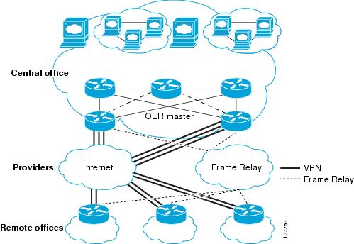
This enhancement allows you to configure two-way VPN optimization. A master controller and border router process are enabled on each side of the VPN. Each site maintains a separate master controller database. VPN routes can be dynamically learned through the tunnel interfaces or can be configured. Prefix and exit link policies are configured for VPN prefixes through a standard Cisco IOS OER configuration.
Protection of Route Prefixes with IPsec over GRE Tunnels
The IPsec-to-GRE model allows a service provider to provide VPN services over the IP backbone. Both the central and remote VPN clients terminate according to the IPsec-to-IPsec model. Prefixes are encapsulated using GRE tunnels. The GRE packet is protected by IPsec. The encapsulated prefixes are forwarded from the central VPN site to a customer headend router that is the other endpoint for GRE. The IPsec-protected GRE packets provide secure connectivity across the IP backbone of the service provider network.
For more information about configuring IPsec over GRE tunnels, see the Dynamic Multipoint IPsec VPNs (Using Multipoint GRE/NHRP to Scale IPsec VPNs) document published at the following URL:
http://www.cisco.com/en/US/tech/tk583/tk372/technologies_white_paper09186a008018983e.shtml
How to Configure VPN IPsec/GRE Tunnel Interfaces As OER-Managed Exit Links
This section contains the following task:
•
Configuring OER to Monitor and Control IPsec VPN Prefixes over GRE Tunnels
Perform this task to configure the IPsec VPN configuration over GRE tunnels. Initially the IPsec VPN is configured on a border router, and the tunnel interface is configured as an OER-managed external interface on the master controller. In this task an IKE policy is defined, a transform set is configured, a crypto profile and a crypto map are defined, and a GRE tunnel is configured.
The GRE tunnel and IPsec protection in this task are configured on the border router. The configuration steps in this task show how to configure a single tunnel. At least two tunnels must be configured on border routers in an OER-managed network. The IPsec configuration must be applied at each tunnel endpoint (the central and remote site).
Configuration of GRE Tunnel Interfaces As OER-Managed Exit Links
GRE tunnel interfaces on the border routers are configured as OER external interfaces on the master controller. At least two external tunnel interfaces must be configured on separate physical interfaces in an OER-managed network. These interfaces can be configured on a single border router or multiple border routers. Internal interfaces are configured normally using a physical interface that is on the border router and is reachable by the master controller.
Restrictions
Cisco IOS OER supports only IPsec/GRE VPNs. No other VPN types are supported.
SUMMARY STEPS
1.
2.
3.
4.
5.
6.
7.
8.
9.
10.
11.
12.
13.
14.
15.
16.
17.
18.
19.
20.
21.
22.
23.
24.
25.
26.
27.
28.
29.
30.
31.
32.
33.
34.
35.
36.
37.
DETAILED STEPS
Step 1
enable
Example:Router> enable
Enables privileged EXEC mode.
•
Step 2
configure terminal
Example:Router# configure terminal
Enters global configuration mode.
Step 3
crypto ipsec security-association lifetime {seconds seconds | kilobytes kilobytes}
Example:Router(config)# crypto ipsec security-association lifetime kilobytes 530000000
Sets global lifetime values used when negotiating IPsec security associations.
•
Step 4
crypto ipsec transform-set transform-set-name transform1 [transform2] [transform3] [transform4]
Example:Router(config)# crypto ipsec transform-set VPN_1 esp-des esp-3des esp-sha-hmac
Enters crypto transform configuration mode to create or modify a transform set—an acceptable combination of security protocols and algorithms.
•
Step 5
mode [tunnel | transport]
Example:Router(cfg-crypto-trans)# mode transport
Sets the mode for the transform set.
•
Step 6
exit
Example:Router(cfg-crypto-trans)# exit
Exits crypto transform configuration mode and enters global configuration mode.
Step 7
crypto map map-name seq-num [ipsec-isakmp]
Example:Router(config)# crypto map TUNNEL 10 ipsec-isakmp
Enters crypto map configuration mode to create or modify a crypto map.
•
Step 8
set peer {host-name [dynamic] [default] | ip-address [default]}Example:Router(config-crypto-map)# set peer 10.4.9.81
Specifies the IPsec peer in the crypto map entry.
Step 9
set transform-set transform-set-name [transform-set-name2...transform-set-name6]
Example:Router(config-crypto-map)# set transform-set VPN_1
Specifies which transform sets can be used with the crypto map entry.
•
Step 10
match address [access-list-id | name]
Example:Router(config-crypto-map)# match address 100
Specifies an extended access list to define IPsec peers for the crypto map entry.
•
Step 11
exit
Example:Router(config-crypto-map)# exit
Exits crypto map configuration mode and enters global configuration mode.
Step 12
crypto ipsec profile name
Example:Router(config)# crypto ipsec profile OER
Defines the IPsec parameters that are to be used for IPsec encryption between two IPsec routers and enters IPsec profile configuration mode.
•
Step 13
set transform-set transform-set-name [transform-set-name2...transform-set-name6]
Example:Router(ipsec-profile)# set transform-set VPN_1
Specifies which transform sets can be used with the crypto map entry.
•
Step 14
exit
Example:Router(ipsec-profile)# exit
Exits IPsec profile configuration mode and enters global configuration mode.
Step 15
crypto map map-name local-address interface-id
Example:Router(config)# crypto map TUNNEL local-address FastEthernet 0/0
Attaches a defined crypto map to the specified interface.
•
Step 16
crypto isakmp key encryption-level key-string {address peer-address [mask] | hostname name} [no-xauth]
Example:Router(config)# crypto isakmp key 0 CISCO address 10.4.9.81 no-xauth
Creates the preshared authentication key.
•
Step 17
crypto isakmp keepalive seconds [retries] [periodic | on-demand]
Example:Router(config)# crypto isakmp keepalive 10
Allows the gateway to send dead peer detection (DPD) messages to the peer.
Step 18
crypto isakmp policy priority
Example:Router(config)# crypto isakmp policy 1
Defines an Internet Key Exchange (IKE) policy and enters ISAKMP policy configuration mode.
Step 19
encryption {des | 3des | aes | aes 192 | aes 256}
Example:Router(config-isakmp)# encryption 3des
Specifies the encryption algorithm within the IKE policy.
•
Step 20
authentication {rsa-sig | rsa-encr | pre-share}
Example:Router(config-isakmp)# authentication pre-share
Specifies the authentication method within the IKE policy.
•
Step 21
exit
Example:Router(config-isakmp)# exit
Exits ISAKMP policy configuration mode and enters global configuration mode.
Step 22
interface type number [name-tag]
Example:Router(config)# interface FastEthernet0/0
Configures an interface type and enters interface configuration mode.
•
Step 23
ip address ip-address mask [secondary]
Example:Router(config-if)# ip address 10.4.9.14 255.255.255.0
Sets a primary or secondary IP address for an interface.
Step 24
crypto map map-name [redundancy standby-name]
Example:Router(config-if)# crypto map TUNNEL
Applies the crypto map set to the interface.
•
Step 25
exit
Example:Router(config-if)# exit
Exits interface configuration mode and enters global configuration mode.
Step 26
interface type number [name-tag]
Example:Router(config)# interface Tunnel0
Configures an interface type and enters interface configuration mode.
•
Step 27
ip address ip-address mask [secondary]
Example:Router(config-if) ip address 10.100.2.1 255.255.0.0
Sets a primary or secondary IP address for an interface.
Step 28
keepalive [period [retries]]
Example:Router(config-if) keepalive 30 5
Enables keepalive packets and specifies the number of times that the Cisco IOS software tries to send keepalive packets without a response before bringing down the interface or before bringing the tunnel protocol down for a specific interface.
Step 29
bandwidth {kbps | inherit [kbps]}
Example:Router(config-if)# bandwidth 500
Router(config-if)# bandwidth inherit
Sets and communicates the current bandwidth value for an interface to higher-level protocols.
Step 30
tunnel mode gre ip
Example:Router(config-if)# tunnel mode gre ip
Sets the encapsulation mode for the tunnel interface.
Note
Step 31
tunnel source {ip-address | interface-type interface-number}
Example:Router(config-if)# tunnel source 10.4.9.14
Sets the source address for a tunnel interface.
•
Step 32
tunnel destination {host-name | ip-address}
Example:Router(config-if)# tunnel destination 10.4.9.81
Specifies the destination for a tunnel interface.
•
Step 33
tunnel protection ipsec profile name [shared]
Example:Router(config-if)# tunnel protection ipsec profile OER
Associates the tunnel interface with the IPsec profile.
•
Step 34
exit
Example:Router(config-if)# exit
Exits interface configuration mode and enters global configuration mode.
Step 35
ip route prefix mask {ip-address | interface-type interface-number [ip-address]} [dhcp] [distance] [name] [permanent] [tag tag]
Example:Router(config)# ip route 10.2.2.2 255.255.255.255 Tunnel0
Establishes a static route.
•
Step 36
access-list access-list-number [dynamic dynamic-name [timeout minutes]] {deny | permit} protocol source source-wildcard destination destination-wildcard [precedence precedence] [tos tos] [log | log-input] [time-range time-range-name] [fragments]
Example:Router(config)# access-list 100 permit gre host 10.4.9.14 host 10.4.9.81
Creates or configures an extended IP access list.
•
•
Step 37
end
Example:Router(config)# end
Exits global configuration mode and enters privileged EXEC mode.
Configuration Examples for Configuring VPN IPsec/GRE Tunnel Interfaces As OER-Managed Exit Links
This section contains the following example:
•
Configuring OER to Monitor and Control GRE/IPsec VPN Prefixes: Example
Figure 2 shows a central VPN site and two remote VPN sites. VPN peering is established through the service provider clouds. An OER-managed network is configured at each site where Cisco IOS OER configuration is applied independently. Each site has a separate master controller and border router process, and each site maintains a separate master controller database.
Figure 2
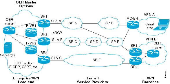
VPN Sites Controlled by OER-Managed Networks
Two GRE tunnels are configured between each remote site and the central site. VPN prefixes are encapsulated in GRE tunnels, which in turn are protected by IPsec encryption. The examples in this section show the configuration for the central VPN site, VPN A, and VPN B.
Central VPN Configuration: OER Master Controller
The central VPN site peers with VPN A and VPN B. A separate policy is defined for each site using an OER map. For VPN A prefixes, a delay policy of 80 ms is configured and out-of-policy prefixes are moved to the first in-policy exit. For VPN B prefixes, a delay policy of 40 ms and a relative loss policy are configured, and out-of-policy prefixes are moved to the best available exit.
key chain OERkey 1key-string CISCO!oer masterloggingborder 10.4.9.6 key-chain OERinterface Ethernet 0/0 externalinterface Ethernet 0/1 internal!border 10.4.9.7 key-chain OERinterface Ethernet 0/0 externalinterface Ethernet 0/1 internal!mode route controlmode monitor bothexit!ip prefix VPN A permit 10.4.9.25oer-map VPNAmatch ip address prefix-list VPNBset delay 800set mode select-exit goodexit!ip prefix VPNB permit 10.4.9.254oer-map VPNBmatch ip address prefix-list VPNCset delay 400set loss relative 100set resolve loss priority 1 variance 10set mode select-exit bestendCentral VPN Configuration: BR1
The following example, starting in global configuration mode, shows the central VPN configuration for BR1:
key chain OERkey 1key-string CISCO!oer borderlocal serial 0/1master 10.4.9.4 key-chain OER!ip route 10.70.1.0 255.255.255.0!route-map REDISTRIBUTE_STATICmatch tag 5000set metric -10exit!router eigrp 1network 10.70.0.0 0.0.0.255redistribute static route-map REDISTRIBUTE_STATICexit!crypto ipsec security-association lifetime kilobytes 530000000crypto ipsec security-association lifetime second 14400crypto ipsec transform-set VPN_1 esp-3des esp-sha-hmacmode transportexit!crypto map TUNNEL 10 ipsec-isakmpset peer 10.4.9.81set transform-set VPN_1match address 100!crypto ipsec profile OERset transform-set VPN_1exitcrypto map TUNNEL local-address Ethernet 0/0!crypto isakmp key 0 CISCO address 10.4.9.81 no-xauthcrypto isakmp keepalive 10crypto isakmp policy 1encryption 3desauthentication pre-shareexit!interface Ethernet0/0ip address 10.4.9.14 255.255.255.0crypto map TUNNELexit!interface Tunnel0ip address 10.100.2.1 255.255.0.0keepalive 30 5bandwidth 500bandwidth inherittunnel mode gre iptunnel source 10.4.9.14tunnel destination 10.4.9.81tunnel protection ipsec profile OERexitCentral VPN Configuration: BR2
The following example, starting in global configuration mode, shows the central VPN configuration of BR2:
key chain OERkey 1key-string CISCO!oer borderlocal Ethernet 0/1master 10.4.9.4 key-chain OER!ip route 10.70.1.0 255.255.255.0!route-map REDISTRIBUTE_STATICmatch tag 5000set metric -10exit!router eigrp 1network 10.70.0.0 0.0.0.255redistribute static route-map REDISTRIBUTE_STATIC!crypto ipsec security-association lifetime kilobytes 530000000crypto ipsec security-association lifetime second 14400crypto ipsec transform-set VPN_1 esp-3des esp-sha-hmacmode transportexit!crypto map TUNNEL 10 ipsec-isakmpset peer 10.4.9.82set transform-set VPN_1match address 100!crypto ipsec profile OERset transform-set VPN_1exitcrypto map TUNNEL local-address Ethernet 0/0!crypto isakmp key 0 CISCO address 10.4.9.82 no-xauthcrypto isakmp keepalive 10crypto isakmp policy 1encryption 3desauthentication pre-shareexit!interface Ethernet0/0ip address 10.4.9.15 255.255.255.0crypto map TUNNELexit!interface Tunnel0ip address 10.100.2.2 255.255.0.0keepalive 30 5bandwidth 500bandwidth inherittunnel mode gre iptunnel source 10.4.9.15tunnel destination 10.4.9.82tunnel protection ipsec profile OERendCentral VPN Configuration: Internal Peers
The following example shows an EIGRP routing process created to establish peering with the border routers and internal peers:
router eigrp 1network 10.50.1.0 0.0.0.255redistribute static route-map REDISTRIBUTE_STATICendVPN A Configuration: MC/BR
The following configuration example, starting in global configuration mode, shows the configuration of VPN A. VPN A is a remote site that is configured for a small office home office (SOHO) client. A single router is deployed. This router peers with service provider B and service provider E. No Interior Gateway Protocol (IGP) is deployed at this network; only a static route is configured to the remote tunnel endpoint at the central site. A delay policy, a loss policy, and optimal exit link selection are configured so that traffic is always routed through the ISP with the lowest delay time and lowest packet loss. A resolve policy is configured to configure loss to have the highest priority. Neither the physical interface configuration nor the router IGP peering configurations are shown in this example.
key chain BR1key 1key-string CISCO!
Note
oer borderlocal Loopback0master 192.168.0.1 key-chain BR1!oer masterlearndelaymode route controldelay threshold 100loss relative 200periodic 300mode select-exit goodresolve loss priority 1 variance 20resolve delay priority 2 variance 10!border 192.168.0.1 key-chain BR1interface Serial0/0 internalinterface Tunnel0 externalinterface Tunnel0 externalexit!crypto ipsec security-association lifetime kilobytes 530000000crypto ipsec security-association lifetime second 14400crypto ipsec transform-set VPN_1 esp-3des esp-sha-hmacmode transportexit!crypto map TUNNEL 10 ipsec-isakmpset peer 10.4.9.81set transform-set VPN_1match address 100!crypto ipsec profile OERset transform-set VPN_1exitcrypto map TUNNEL local-address Ethernet 0/0!crypto isakmp key 0 CISCO address 10.4.9.81 no-xauthcrypto isakmp keepalive 10crypto isakmp policy 1encryption 3desauthentication pre-shareexit!interface Ethernet0/0ip address 10.4.9.14 255.255.255.0crypto map TUNNELexit!interface Tunnel0ip address 10.100.2.1 255.255.0.0keepalive 30 5bandwidth 500bandwidth inherittunnel mode gre iptunnel source 10.4.9.14tunnel destination 10.4.9.81tunnel protection ipsec profile OERexit!
Note
VPN B Configuration: OER Master Controller
The following example, starting in global configuration mode, shows the master controller configuration in VPN B. Load distribution and route control mode are enabled. Out-of-policy prefixes are configured to be moved to the first in-policy exit.
key chain OERkey 1key-string CISCO!oer masterloggingborder 10.4.9.6 key-chain OERinterface Ethernet 0/0 externalinterface Ethernet 0/1 internal!border 10.4.9.7 key-chain OERinterface Ethernet 0/0 externalinterface Ethernet 0/1 internal!mode route controlmode select-exit goodmax-range utilization!learndelayendVPN B Configuration: BR1
The following example, starting in global configuration mode, shows the VPN B configuration for BR1:
key chain OERkey 1key-string CISCO!oer borderlocal Ethernet 0/1master 10.4.9.4 key-chain OER!route-map REDISTRIBUTE_STATICmatch tag 5000set metric -10exit!router ripnetwork 10.60.1.0redistribute static route-map REDISTRIBUTE_STATICend!crypto ipsec security-association lifetime kilobytes 530000000crypto ipsec security-association lifetime second 14400crypto ipsec transform-set VPN_1 esp-3des esp-sha-hmacmode transportexit!crypto map TUNNEL 10 ipsec-isakmpset peer 10.4.9.82set transform-set VPN_1match address 100!crypto ipsec profile OERset transform-set VPN_1exitcrypto map TUNNEL local-address Ethernet 0/0!crypto isakmp key 0 CISCO address 10.4.9.82 no-xauthcrypto isakmp keepalive 10crypto isakmp policy 1encryption 3desauthentication pre-shareexit!interface Ethernet0/0ip address 10.4.9.15 255.255.255.0crypto map TUNNELexit!interface Tunnel0ip address 10.100.2.2 255.255.0.0keepalive 30 5bandwidth 500bandwidth inherittunnel mode gre iptunnel source 10.4.9.15tunnel destination 10.4.9.82tunnel protection ipsec profile OERendVPN B Configuration: BR2
The following example, starting in global configuration mode, shows the VPN B configuration for BR2:
key chain OERkey 1key-string CISCO!oer borderlocal Ethernet 0/1master 10.4.9.4 key-chain OERexit!route-map REDISTRIBUTE_STATICmatch tag 5000set metric -10exit!router ripnetwork 10.60.1.0redistribute static route-map REDISTRIBUTE_STATICexit!crypto ipsec security-association lifetime kilobytes 530000000crypto ipsec security-association lifetime second 14400crypto ipsec transform-set VPN_1 esp-3des esp-sha-hmacmode transportexit!crypto map TUNNEL 10 ipsec-isakmpset peer 10.4.9.82set transform-set VPN_1match address 100!crypto ipsec profile OERset transform-set VPN_1exitcrypto map TUNNEL local-address Ethernet 0/0!crypto isakmp key 0 CISCO address 10.4.9.82 no-xauthcrypto isakmp keepalive 10crypto isakmp policy 1encryption 3desauthentication pre-shareexit!interface Ethernet0/0ip address 10.4.9.15 255.255.255.0crypto map TUNNELexit!interface Tunnel0ip address 10.100.2.2 255.255.0.0keepalive 30 5bandwidth 500bandwidth inherittunnel mode gre iptunnel source 10.4.9.15tunnel destination 10.4.9.82tunnel protection ipsec profile OERendVPN B Configuration: Internal Peers
The following example shows a Routing Information Protocol (RIP) routing process created to establish peering with the border routers and internal peers:
router ripnetwork 10.60.1.0endWhere to Go Next
This document describes a specific implementation of OER and presumes that you are familiar with the OER technology. If you want to review more information about OER, proceed to the Cisco IOS Optimized Edge Routing Overview module, followed by the Setting Up OER Network Components module. To learn more about the other OER phases, read through the other modules in the following list:
•
•
•
•
After you understand the various OER phases you may want to review other OER Solutions modules that are listed under "Related Documents" section.
Additional References
The following sections provide references related to configuring VPN IPsec/GRE tunnel interfaces as OER-managed exit links.
Related Documents
Cisco OER technology overview
Concepts and configuration tasks required to set up OER network components.
OER solution module: voice traffic optimization using OER active probes.
Cisco OER commands: complete command syntax, command mode, command history, defaults, usage guidelines and examples
Cisco IOS Optimized Edge Routing Command Reference, Release 12.4T
Cisco OER CPU and memory and test information
Cisco Optimized Edge Routing Cpu And Memory Performance Tests
Key Chain Authentication: information about authentication key configuration and management in Cisco IOS Software
"Managing Authentication Keys" section of the Cisco IOS IP Routing Protocols Configuration Guide, Release 12.4
IP Routing Protocol commands
Cisco IOS IP Routing Protocols Command Reference, Release 12.4T
IP Routing Protocol configuration tasks
Cisco IOS IP Routing Protocols Configuration Guide, Release 12.4
Technical Assistance
Feature Information for Configuring VPN IPsec/GRE Tunnel Interfaces As OER-Managed Exit Links
Table 1 lists the features in this module and provides links to specific configuration information. Only features that were introduced or modified in Cisco IOS Release 12.3(11)T or a later release appear in the table.
For information on a feature in this technology that is not documented here, see the "Cisco IOS Optimized Edge Routing Feature Roadmap."
Not all commands may be available in your Cisco IOS software release. For release information about a specific command, see the command reference documentation.
Use Cisco Feature Navigator to find information about platform support and software image support. Cisco Feature Navigator enables you to determine which Cisco IOS and Catalyst OS software images support a specific software release, feature set, or platform. To access Cisco Feature Navigator, go to http://www.cisco.com/go/cfn. An account on Cisco.com is not required.
Note

Any Internet Protocol (IP) addresses used in this document are not intended to be actual addresses. Any examples, command display output, and figures included in the document are shown for illustrative purposes only. Any use of actual IP addresses in illustrative content is unintentional and coincidental.
© 2006 Cisco Systems, Inc. All rights reserved.