Contents

MPLS Traffic Engineering Shared Risk Link Groups

The MPLS Traffic Engineering: Shared Risk Link Groups feature enhances backup tunnel path selection so that a backup tunnel avoids using links that are in the same Shared Risk Link Group (SRLG) as interfaces the backup tunnel is protecting.

SRLGs refer to situations where links in a network share a common fiber (or a common physical attribute). If one link fails, other links in the group may fail too. Links in the group have a shared risk.

Finding Feature Information

Your software release may not support all the features documented in this module. For the latest caveats and feature information, see Bug Search Tool and the release notes for your platform and software release. To find information about the features documented in this module, and to see a list of the releases in which each feature is supported, see the feature information table at the end of this module.

Use Cisco Feature Navigator to find information about platform support and Cisco software image support. To access Cisco Feature Navigator, go to www.cisco.com/​go/​cfn. An account on Cisco.com is not required.

Prerequisites for MPLS Traffic Engineering Shared Risk Link Groups

  • You must configure Fast Reroutable tunnels.

  • You must enable the autotunnel backup.

Restrictions for MPLS Traffic Engineering Shared Risk Link Groups

  • The backup tunnel must be within a single area.

  • Manually created backup tunnels do not automatically avoid SRLGs of protected interfaces.

  • A primary tunnel cannot be specified to avoid links belonging to specified SRLGS.

Information About MPLS Traffic Engineering Shared Risk Link Groups

MPLS Traffic Engineering Brief Overview

Multiprotocol Label Switching (MPLS) is an Internet Engineering Task Force (IETF)-specified framework that provides for the efficient designation, routing, forwarding, and switching of traffic flows through the network.

Traffic engineering (TE) is the process of adjusting bandwidth allocations to ensure that enough is left for high-priority traffic.

In MPLS TE, the upstream router creates a network tunnel for a particular traffic stream, then fixes the bandwidth available for that tunnel.

MPLS Traffic Engineering Shared Risk Link Groups

SRLGs refer to situations where links in a network share a common fiber (or a common physical attribute). If one link fails, other links in the group may fail too. Links in the group have a shared risk.

Backup tunnels should avoid using links in the same SRLG as interfaces they are protecting. Otherwise, when the protected link fails the backup tunnel fails too.

The figure below shows a primary label-switched path (LSP) from router R1 to router R5. The LSP protects against the failure of the R2-R3 link at R2 via a backup tunnel to R4. If the R2-R3 link fails, link protection reroutes the LSP along the backup tunnel. However, the R2-R3 link and one of the backup tunnel links are in the same SRLG. So if the R2-R3 link fails, the backup tunnel may fail too.
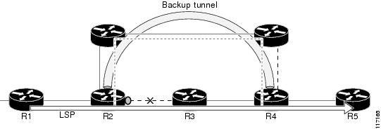
Figure 1. Backup Tunnel in the Same SRLG as the Interface It Is Protecting

The MPLS TE SRLG feature enhances backup tunnel path selection so a backup tunnel can avoid using links that are in the same SRLG as the interfaces it is protecting.

There are two ways for a backup tunnel to avoid the SRLGs of its protected interface:

  • The router does not create the backup tunnel unless it avoids SRLGs of the protected interface.

  • The router tries to avoid SRLGs of the protected interface, but if that is not possible the router creates the backup tunnel anyway. In this case there are two explicit paths. The first explicit path tries to avoid the SRLGs of the protected interface. If that does not work, the backup tunnel uses the second path (which ignores SRLGs).


Note


Only backup tunnels that routers create automatically (called autotunnel backup) can avoid SRLGs of protected interfaces. For more information about these backup tunnels, see the Autotunnel Backup for MPLS TE SRLGs.


To activate the MPLS TE SRLG feature, you must do the following:

  • Configure the SRLG membership of each link that has a shared risk with another link.

  • Configure the routers to automatically create backup tunnels that avoid SRLGs of the protected interfaces.

For a detailed explanation of the configuration steps, see the How to Configure MPLS Traffic Engineering Shared Risk Link Groups.

Open Shortest Path First (OSPF) and Intermediate System-to-Intermediate System (IS-IS) flood the SRLG membership information (including other TE link attributes such as bandwidth availability and affinity) so that all routers in the network have the SRLG information for each link. With this topology information, routers can compute backup tunnel paths that exclude links having SRLGs in common with their protected interfaces. As shown in the figure below, the backup tunnel avoids the link between R2 and R3, which shares an SRLG with the protected interface.
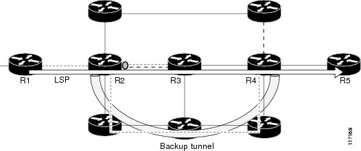
Figure 2. Backup Tunnel That Avoids SRLG of Protected Interface

Fast Reroute Protection for MPLS TE SRLGs

Fast Reroute (FRR) protects MPLS TE LSPs from link and node failures by locally repairing the LSPs at the point of failure. This protection allows data to continue to flow on LSPs while their headend routers attempt to establish new end-to-end LSPs to replace them. FRR locally repairs the protected LSPs by rerouting them over backup tunnels that bypass failed links or nodes.

Backup tunnels that bypass only a single link of the LSP’s path provide link protection. They protect LSPs if a link along their path fails by rerouting the LSP’s traffic to the next hop (bypassing the failed link). These are referred to as next-hop (NHOP) backup tunnels because they terminate at the LSP’s next hop beyond the point of failure. The figure below illustrates an NHOP backup tunnel.
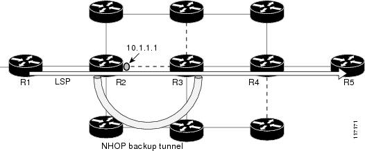
Figure 3. NHOP Backup Tunnel

FRR provides node protection for LSPs. Backup tunnels that bypass next-hop nodes along LSP paths are called next-next-hop (NNHOP) backup tunnels because they terminate at the node following the next-hop node of the LSP paths, thereby bypassing the next-hop node. They protect LSPs if a node along their path fails by enabling the node upstream of the failure to reroute the LSPs and their traffic around the failed node to the next-next hop. FRR supports the use of Resource Reservation Protocol (RSVP) hellos to accelerate the detection of node failures. NNHOP backup tunnels also provide protection from link failures, because they bypass the failed link and the node.

The figure below illustrates an NNHOP backup tunnel.
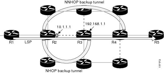
Figure 4. NNHOP Backup Tunnel

Autotunnel Backup for MPLS TE SRLGs

Autotunnel backup is the ability of routers to create backup tunnels automatically. Therefore, you do not need to preconfigure each backup tunnel and then assign the backup tunnel to the protected interface. Only automatically created backup tunnels can avoid SRLGs or their protected interfaces.

For information about backup tunnels, see the Fast Reroute Protection for MPLS TE SRLGs.

For detailed information about autotunnel backup and how you can change the default command values, see MPLS Traffic Engineering (TE)--AutoTunnel Primary and Backup.

To globally activate the autotunnel backup feature, enter the mpls traffic-eng auto-tunnel backup command.

The figure below illustrates an NNHOP automatically generated backup tunnel that excludes the router 192.168.1.1 and terminates at router R4. The backup tunnel must avoid touching any links of 192.168.1.1.
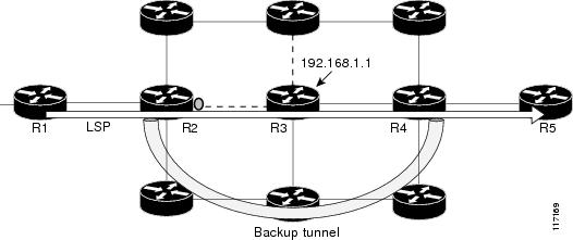
Figure 5. Autotunnel Backup for NNHOP

The figure below illustrates an NHOP automatically generated backup tunnel that terminates at router R3 and avoids the link 10.1.1.1, not the entire node.

Figure 6. Autotunnel Backup for NHOP


Note


NNHOP excludes the router ID (the entire router must be excluded; that is, no link of the router can be included in the backup tunnel’s path). NHOP excludes only the link when the backup tunnel’s path is computed.


How to Configure MPLS Traffic Engineering Shared Risk Link Groups

Configuring MPLS TE SRLG Membership of Each Link That Has a Shared Risk with Another Link

Perform the following task to configure MPLS TE SRLG membership of each link that has a shared risk with another link. Configuring SRLG membership enhances backup tunnel path selection so that a backup tunnel avoids using links that are in the same SRLG as interfaces the backup tunnel is protecting.

Enter the commands on the physical interface.

SUMMARY STEPS

    1.    enable

    2.    configure terminal

    3.    interface type slot/port

    4.    mpls traffic-eng srlg [number] [

    5.    mpls traffic-eng srlg end


DETAILED STEPS
     Command or ActionPurpose
    Step 1 enable


    Example:
    Router> enable
     

    Enables privileged EXEC mode.

    • Enter your password if prompted.

     
    Step 2 configure terminal


    Example:
    Router# configure terminal
     

    Enters global configuration mode.

     
    Step 3 interface type slot/port


    Example:
    Router(config)# interface pos 1/1/1 
     

    Specifies an interface and enters interface configuration mode.

    • The type argument is the type of interface to be configured.

    • The slot argument is the slot number. Refer to the appropriate hardware manual for slot and port information.

    • The /port argument is the port number. Refer to the appropriate hardware manual for slot and port information. The slash (/) is required.

     
    Step 4 mpls traffic-eng srlg [number] [


    Example:
    Router(config-if)# mpls traffic-eng srlg 5 
     

    Configures the SRLG membership of a link (interface).

    • The number argument is an SRLG identifier. Valid values are 0 to 4,294,967,295.

    Note   

    To make the link a member of multiple SRLGs, enter the mpls traffic-eng srlg command multiple times.

     
    Step 5 mpls traffic-eng srlg end


    Example:
    Router(config-if)# end
     

    Exits to privileged EXEC mode.


    Configuring the Routers That Automatically Create Backup Tunnels to Avoid MPLS TE SRLGs

    Perform the following task to configure routers that automatically create backup tunnels to avoid MPLS TE SRLGs of their protected interfaces. Backup tunnels provide link protection by rerouting traffic to the next hop bypassing failed links or in this instance by avoiding SRLGs.

    SUMMARY STEPS

      1.    enable

      2.    configure terminal

      3.    mpls traffic-eng auto-tunnel backup srlg exclude [force | preferred]

      4.    end


    DETAILED STEPS
       Command or ActionPurpose
      Step 1 enable


      Example:
      Router> enable
       

      Enables privileged EXEC mode.

      • Enter your password if prompted.

       
      Step 2 configure terminal


      Example:
      Router# configure terminal
       

      Enters global configuration mode.

       
      Step 3 mpls traffic-eng auto-tunnel backup srlg exclude [force | preferred]


      Example:
      Router(config)# mpls traffic-eng auto-tunnel backup srlg exclude force
       

      Specifies that autocreated backup tunnels should avoid SRLGs of its protected interface.

      • The force keyword forces the backup tunnel to avoid SRLGs of its protected interface or interfaces.

      • The preferred keyword causes the backup tunnel to try to avoid SRLGs of its protected interface or interfaces, but the backup tunnel can be created if SRLGs cannot be avoided.

       
      Step 4 end


      Example:
      Router(config)# end 
       

      Returns to privileged EXEC mode.


      Verifying the MPLS Traffic Engineering Shared Risk Link Groups Configuration

      SUMMARY STEPS

        1.    enable

        2.    show running-config

        3.    show mpls traffic-eng link-management interfacesinterface slot/port

        4.    show mpls traffic-eng topology

        5.    show mpls traffic-eng topology srlg

        6.    show mpls traffic-eng topology brief

        7.    show mpls traffic-eng link-management advertisements

        8.    show ip rsvp fast-reroute

        9.    mpls traffic-eng auto-tunnel backup srlg exclude force

        10.    show ip explicit-paths

        11.    show mpls traffic-eng tunnels tunnel num

        12.    mpls traffic-eng auto-tunnel backup srlg exclude preferred

        13.    show ip explicit-paths

        14.    show ip rsvp fast-reroute

        15.    exit


      DETAILED STEPS
        Step 1   enable

        Use this command to enable privileged EXEC mode. Enter your password, if prompted. For example:


        Example:
        Router> enable
        Router#
        
        Step 2   show running-config

        Use the following commands to configure the SRLG membership of the interface pos 1/3/1 and to verify that the configuration is as expected. For example:


        Example:
        Router# configure terminal
        Router(config)# interface pos 1/3/1 
        Router(config-if)# mpls traffic-eng srlg 1
        Router(config-if)# mpls traffic-eng srlg 2
        Router(config-if)# end
        Router# show running-config
         
        interface POS 1/3/1
         ip address 10.0.0.33 255.255.255.255
         no ip directed-broadcast
         ip router isis
         encapsulation ppp
         no ip mroute-cache
         mpls traffic-eng tunnels
         mpls traffic-eng backup-path Tunnel5000
         mpls traffic-eng srlg 1
         mpls traffic-eng srlg 2
         tag-switching ip
         crc 32
         clock source internal
         pos ais-shut
         pos report rdool
         pos report lais
         pos report lrdi
         pos report pais
         pos report prdi
         pos report sd-ber
         isis circuit-type level-2-only
         ip rsvp bandwidth 20000 20000 sub-pool 5000
        

        This verifies that the Packet over SONET (POS) interface pos 1/3/1 is associated that SRLG 1 and SRLG 2.

        Step 3   show mpls traffic-eng link-management interfacesinterface slot/port

        Use this command to show the SRLG membership configured on interface pos 1/3/1. For example:


        Example:
        Router# show mpls traffic-eng link-management interfaces pos 1/3/1 
        System Information::
            Links Count:         11
        Link ID:: PO1/3/1 (10.0.0.33)
            Link Status:
              SRLGs:               1 2
              Physical Bandwidth:  2488000 kbits/sec
              Max Res Global BW:   20000 kbits/sec (reserved:0% in, 0% out)
              Max Res Sub BW:      5000 kbits/sec (reserved:0% in, 0% out)
              MPLS TE Link State:  MPLS TE on, RSVP on, admin-up, flooded
              Inbound Admission:   allow-all
              Outbound Admission:  allow-if-room
              Admin. Weight:       10 (IGP)
              IGP Neighbor Count:  1
              IGP Neighbor:        ID 0000.0000.0004.00, IP 10.0.0.34 (Up)
            Flooding Status for each configured area [1]:
              IGP Area[1]: isis  level-2: flooded
        
        Step 4   show mpls traffic-eng topology

        Use this command to show the SRLG link membership flooded via the Interior Gateway Protocol (IGP). For example:


        Example:
        Router# show mpls traffic-eng topology
         
        My_System_id:0000.0000.0003.00 (isis  level-2)
        Signalling error holddown:10 sec Global Link Generation 9
        IGP Id:0000.0000.0003.00, MPLS TE Id:10.0.3.1 Router Node  (isis
        level-2)
              link[0]:Point-to-Point, Nbr IGP Id:0000.0000.0004.00,
        nbr_node_id:2, gen:9
                  frag_id 0, Intf Address:10.0.0.33, Nbr Intf Address:10.0.0.34
                  TE metric:10, IGP metric:10, attribute_flags:0x0
                  SRLGs:1 2
                  physical_bw:2488000 (kbps), max_reservable_bw_global:20000
        (kbps)
                  max_reservable_bw_sub:5000 (kbps)
                                         Global Pool       Sub Pool
                       Total Allocated   Reservable        Reservable
                       BW (kbps)         BW (kbps)         BW (kbps)
                       ---------------   -----------       ----------
                bw[0]:           0            20000             5000
                bw[1]:           0            20000             5000
                bw[2]:           0            20000             5000
                bw[3]:           0            20000             5000
                bw[4]:           0            20000             5000
                bw[5]:           0            20000             5000
        
        Step 5   show mpls traffic-eng topology srlg

        Use this command to display all the links in the network that are members of a given SRLG. For example:


        Example:
        Router# show mpls traffic-eng topology srlg
        MPLS TE Id:0000.0000.0003.00 (isis  level-2)
          SRLG:1
             10.0.0.33
          SRLG:2
             10.0.0.33
        

        The following command shows that there are two links in SRLG 1:


        Example:
        Router# show mpls traffic-eng topology srlg
        MPLS TE Id:0000.0000.0003.00 (isis  level-2)
          SRLG:1
             10.0.0.33
             10.0.0.49
        
        Step 6   show mpls traffic-eng topology brief

        Use this command to display brief topology information:


        Example:
        Router# show mpls traffic-eng topology brief
        My_System_id:0000.0000.0003.00 (isis  level-2)
        Signalling error holddown:10 sec Global Link Generation 9
        IGP Id:0000.0000.0003.00, MPLS TE Id:10.0.3.1 Router Node  (isis
        level-2)
              link[0]:Point-to-Point, Nbr IGP Id:0000.0000.0004.00,
        nbr_node_id:2, gen:9
                  frag_id 0, Intf Address:10.0.0.33, Nbr Intf Address:10.0.0.34
                  TE metric:10, IGP metric:10, attribute_flags:0x0
                  SRLGs:1 2
        
        Step 7   show mpls traffic-eng link-management advertisements

        Use this command to show local link information that MPLS TE link management is currently flooding into the global TE topology. For example:


        Example:
        Router# show mpls traffic-eng link-management advertisements
         
        Flooding Status:      ready
        Configured Areas:     1
        IGP Area[1] ID::  isis  level-2
          System Information::
            Flooding Protocol:    ISIS
          Header Information::
            IGP System ID:        0000.0000.0003.00
            MPLS TE Router ID:    10.0.3.1
            Flooded Links:        2
          Link ID::  0
            Link Subnet Type:     Point-to-Point
            Link IP Address:      10.0.0.49
            IGP Neighbor:         ID 0000.0000.0007.00, IP 10.0.0.50
            TE metric:            80000
            IGP metric:           80000
            SRLGs:                None
            Physical Bandwidth:   622000 kbits/sec
            Res. Global BW:       20000 kbits/sec
            Res. Sub BW:          5000 kbits/sec
            Downstream::
                                        Global Pool   Sub Pool
                                        -----------   --------------
              Reservable Bandwidth[0]:  20000         5000 kbits/sec
              Reservable Bandwidth[1]:  20000         5000 kbits/sec
              Reservable Bandwidth[2]:  20000         5000 kbits/sec
              Reservable Bandwidth[3]:  20000         5000 kbits/sec
              Reservable Bandwidth[4]:  20000         5000 kbits/sec
              Reservable Bandwidth[5]:  20000         5000 kbits/sec
              Reservable Bandwidth[6]:  20000         5000 kbits/sec
              Reservable Bandwidth[7]:  20000         5000 kbits/sec
            Attribute Flags:      0x00000000
          Link ID::  1
            Link Subnet Type:     Point-to-Point
            Link IP Address:      10.0.0.33
            IGP Neighbor:         ID 0000.0000.0004.00, IP 10.0.0.34
            TE metric:            10
            IGP metric:           10
            SRLGs:                1
            Physical Bandwidth:   2488000 kbits/sec
            Res. Global BW:       20000 kbits/sec
            Res. Sub BW:          5000 kbits/sec
            Downstream::
                                        Global Pool   Sub Pool
                                        -----------   --------------
              Reservable Bandwidth[0]:  20000         5000 kbits/sec
              Reservable Bandwidth[1]:  20000         5000 kbits/sec
              Reservable Bandwidth[2]:  20000         5000 kbits/sec
              Reservable Bandwidth[3]:  20000         5000 kbits/sec
              Reservable Bandwidth[4]:  20000         5000 kbits/sec
              Reservable Bandwidth[5]:  20000         5000 kbits/sec
              Reservable Bandwidth[6]:  20000         5000 kbits/sec
              Reservable Bandwidth[7]:  20000         5000 kbits/sec
            Attribute Flags:      0x00000000
        
        Step 8   show ip rsvp fast-reroute

        Use this command to show that the primary tunnel is going over Pos1/3/1 on R3, on which SLRG 1 is configured. For example:


        Example:
        Router# show ip rsvp fast-reroute 
        Primary    Protect      BW      Backup
        Tunnel     I/F        BPS:Type  Tunnel:Label  State   Level   Type
        -------    -------    --------  ------------  -----   -----   ----
        R3-PRP_t0  PO1/3/1 0:G  None      None          None    None    None
        
        Step 9   mpls traffic-eng auto-tunnel backup srlg exclude force

        Use the following commands to configure autotunnel backup with the force keyword. For example:


        Example:
        Router# configure terminal 
        Router(config)# mpls traffic-eng auto-tunnel backup 
        Router(config)# mpls traffic-eng auto-tunnel backup srlg exclude force 
        Router(config)# exit
        
        Step 10   show ip explicit-paths

        Use the following command to verify that the force keyword is configured with the pos1/3/1 link excluded from the IP explicit path. For example:


        Example:
        Router# show ip explicit-paths
         
        PATH __dynamic_tunnel65436 (loose source route, path complete,
        generation 24, status non-configured)
            1:exclude-address 10.0.0.33
            2:exclude-srlg    10.0.0.33
        
        Step 11   show mpls traffic-eng tunnels tunnel num

        Use the following command to show that autotunnel backup is configured but is down because the headend router does not have any other path to signal and it cannot use pos1/2/1 because it belongs in the same SRLG; that is, SRLG 1. For example:


        Example:
        Router# show mpls traffic-eng tunnels tunnel 65436
        Name:R3-PRP_t65436                       (Tunnel65436) Destination:
        10.0.4.1
          Status:
            Admin:up         Oper:down   Path:not valid   Signalling:Down
            path option 1, type explicit __dynamic_tunnel65436
          Config Parameters:
            Bandwidth:0        kbps (Global)  Priority:7  7   Affinity:
        0x0/0xFFFF
            Metric Type:TE (default)
            AutoRoute: disabled  LockDown:disabled  Loadshare:0
        bw-based
            auto-bw:disabled
          Shortest Unconstrained Path Info:
            Path Weight:10 (TE)
            Explicit Route:10.0.0.34 10.0.4.1
          History:
            Tunnel:
              Time since created:5 minutes, 29 seconds
            Path Option 1:
              Last Error:PCALC::No path to destination, 0000.0000.0004.00
        
        Step 12   mpls traffic-eng auto-tunnel backup srlg exclude preferred

        The following commands configure autotunnel backup with the preferred keyword. For example:


        Example:
        Router# configure terminal
        Router(config)# mpls traffic-eng auto-tunnel backup
        Router(config)# mpls traffic-eng auto-tunnel backup srlg exclude preferred
        Router(config)# exit
        
        Step 13   show ip explicit-paths

        The following command shows two explicit paths. The first path avoids the SRLGs of the protected interface. The second path does not avoid the SRLGs. For example:


        Example:
        Router# show ip explicit-paths
         
        PATH __dynamic_tunnel65436 (loose source route, path complete,
        generation 30, status non-configured)
            1:exclude-address 10.0.0.33
            2:exclude-srlg    10.0.0.33
        PATH __dynamic_tunnel65436_pathopt2 (loose source route, path complete,
        generation 33, status non-configured)
            1:exclude-address 10.0.0.33
        
        Step 14   show ip rsvp fast-reroute

        The following command shows that the primary tunnel is protected with autotunnel backup using the second path option (see Step 10) that does not avoid the SRLGs. For example:


        Example:
        Router# show ip rsvp fast-reroute 
        Primary    Protect      BW      Backup
        Tunnel     I/F        BPS:Type  Tunnel:Label  State   Level   Type
        -------    -------    --------  ------------  -----   -----   ----
        R3-PRP_t0  PO1/3/1 0:G  0:G       Tu65436:0     Ready   any-unl nhop
        

        The following command shows the path options for the tunnel Tu65436:


        Example:
        Router# show mpls traffic-eng tunnels tunnel 65436 
        Name:R3-PRP_t65436                       (Tunnel65436) Destination:
        10.0.4.1
          Status:
            Admin:up         Oper:up     Path:valid       Signalling:connected
            path option 2, type explicit __dynamic_tunnel65436_pathopt2 (Basis
        for Setup, path weight 80020)
            path option 1, type explicit __dynamic_tunnel65436
          Config Parameters:
            Bandwidth:0        kbps (Global)  Priority:7  7   Affinity:
        0x0/0xFFFF
            Metric Type:TE (default)
            AutoRoute: disabled  LockDown:disabled  Loadshare:0
        bw-based
            auto-bw:disabled
          Active Path Option Parameters:
            State:explicit path option 2 is active
            BandwidthOverride:disabled  LockDown:disabled  Verbatim:disabled
        InLabel  : -
          OutLabel :POS1/2/1, 23
          RSVP Signalling Info:
               Src 10.0.3.1, Dst 10.0.4.1, Tun_Id 65436, Tun_Instance 3
            RSVP Path Info:
              My Address:10.0.3.1
              Explicit Route:10.0.0.50 10.0.0.66 10.0.0.113 10.0.4.1
              Record   Route:  NONE
              Tspec:ave rate=0 kbits, burst=1000 bytes, peak rate=0 kbits
            RSVP Resv Info:
              Record   Route:  NONE
              Fspec:ave rate=0 kbits, burst=1000 bytes, peak rate=0 kbits
          Shortest Unconstrained Path Info:
            Path Weight:10 (TE)
            Explicit Route:10.0.0.34 10.0.4.1
        
        Step 15   exit

        Use this command to exit to user EXEC mode. For example:


        Example:
        Router# exit
        Router>
        

        Configuration Examples for MPLS Traffic Engineering Shared Risk Link Groups

        Configuring the SRLG Membership of Each Link That Has a Shared Risk with Another Link Example

        The following example shows how to specify that the SRLG membership of each link has a shared risk with another link.

        As shown in the figure below and in the following commands:

        • link R2-R3 = SRLG5

        • link R2-R3 = SRLG6

        • link R7-R4 = SRLG5

        • link R1-R2 = SRLG6

        Router1# configure terminal
        Router1# interface pos 1/0
        Router1(config-if)# mpls traffic-eng srlg 6
        
        Router2# configure terminal
        Router2# interface pos 1/1
        Router2(config-if)# mpls traffic-eng srlg 5
        Router2(config-if)# mpls traffic-eng srlg 6
        Router7# configure terminal
        Router7# interface pos 3/0
        Router7(config-if)# mpls traffic-eng srlg 5
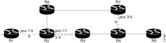
        
        Figure 7. SRLG Membership

        Configuring the Routers That Automatically Create Backup Tunnels to Avoid SRLGs Example

        The following example shows how to specify that automatically created backup tunnels are forced to avoid SRLGs of their protected interfaces:

        Router# configure terminal
        Router(config)# mpls traffic-eng auto-tunnel backup
        Router(config)# mpls traffic-eng auto-tunnel backup srlg exclude force
         

        The figure below illustrates the automatically created NNHOP backup tunnel that would be created to avoid SRLGs of the protected interface if the following conditions exist:

        The exclude address is 192.168.1.1.

        The link at R2 has an IP address of 10.1.1.1.

        The backup tunnel’s explicit path avoids links that have a membership in the same SRLG as the link whose IP address is 10.1.1.1.
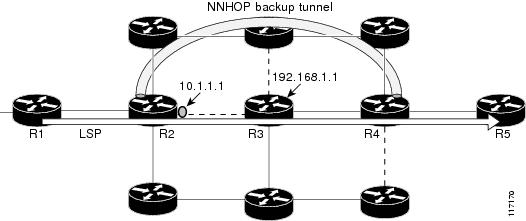
        Figure 8. srlg exclude force--NNHOP Autobackup Tunnel

        The figure below illustrates the automatically created NHOP backup tunnel that would be created.

        Figure 9. srlg exclude force--NHOP Autobackup Tunnel

        Additional References

        Related Documents

        Related Topic

        Document Title

        Fast Reroute

        MPLS TE: Link and Node Protection, with RSVP Hellos Support (with Fast Tunnel Interface Down Detection)

        IS-IS

        Integrated IS-IS Routing Protocol Overview

        OSPF

        Configuring OSPF

        Autotunnel backups

        MPLS Traffic Engineering AutoTunnel Primary and Backup

        Standards

        Standard

        Title

        None

        --

        MIBs

        MIB

        MIBs Link

        None

        To locate and download MIBs for selected platforms, Cisco IOS releases, and feature sets, use Cisco MIB Locator found at the following URL:

        http:/​/​www.cisco.com/​go/​mibs

        RFCs

        RFC

        Title

        draft-ietf-isis-gmpls-extensions-16.txt

        IS-IS Extensions in Support of Generalized MPLS

        Technical Assistance

        Description

        Link

        The Cisco Support website provides extensive online resources, including documentation and tools for troubleshooting and resolving technical issues with Cisco products and technologies.

        To receive security and technical information about your products, you can subscribe to various services, such as the Product Alert Tool (accessed from Field Notices), the Cisco Technical Services Newsletter, and Really Simple Syndication (RSS) Feeds.

        Access to most tools on the Cisco Support website requires a Cisco.com user ID and password.

        http:/​/​www.cisco.com/​techsupport

        Feature Information for MPLS Traffic Engineering Shared Risk Link Groups

        The following table provides release information about the feature or features described in this module. This table lists only the software release that introduced support for a given feature in a given software release train. Unless noted otherwise, subsequent releases of that software release train also support that feature.

        Use Cisco Feature Navigator to find information about platform support and Cisco software image support. To access Cisco Feature Navigator, go to www.cisco.com/​go/​cfn. An account on Cisco.com is not required.

        Table 1 Feature Information for MPLS Traffic Engineering Shared Risk Link Groups

        Feature Name

        Releases

        Feature Information

        MPLS Traffic Engineering: Shared Risk Link Groups

        12.0(28)S

        12.0(29)S

        12.2(33)SRA

        12.2(33)SXH

        12.4(20)T

        Cisco IOS XE Release 3.5S

        The MPLS Traffic Engineering: Shared Risk Link Groups feature enhances backup tunnel path selection so that a backup tunnel avoids using links that are in the same Shared Risk Link Group (SRLG) as interfaces the backup tunnel is protecting.

        SRLGs refer to situations where links in a network share a common fiber (or a common physical attribute). If one link fails, other links in the group may fail too. Links in the group have a shared risk.

        This document contains information about and instructions for configuring the MPLS Traffic Engineering Shared Risk Link Groups feature

        In 12.0(28)S, this feature was introduced.

        In 12.0(29)S, support was added for Open Shortest Path First (OSPF).

        In 12.2(33)SRA, this feature was integrated into a Cisco IOS 12.2SRA release

        In 12.2(33)SXH, this feature was integrated into a Cisco IOS 12.2SXH release.

        In 12.4(20)T, this feature was integrated into a Cisco IOS 12.4T release.

        In Cisco IOS XE Release 3.5S, this feature was integrated into Cisco IOS XE Release 3.5S.

        The following commands were introduced or modified: mpls traffic-eng auto-tunnel backup srlg exclude, mpls traffic-eng srlg, show ip explicit-paths, show mpls traffic-eng link-management advertisements, show mpls traffic-eng link-management interfaces, and show mpls traffic-eng topology.

        Glossary

        Fast Reroute --A mechanism for protecting MPLS traffic engineering (TE) LSPs from link and node failure by locally repairing the LSPs at the point of failure. This protection allows data to continue to flow on them while their headend routers attempt to establish end-to-end LSPs to replace them. FRR locally repairs the protected LSPs by rerouting them over backup tunnels that bypass failed links or nodes.

        hop --Passage of a data packet between two network nodes (for example, between two routers).

        IGP --Interior Gateway Protocol. An Internet protocol used to exchange routing information within an autonomous system.

        interface --A network connection.

        IP address --A 32-bit address assigned to hosts using TCP/IP. An IP address belongs to one of five classes (A, B, C, D, or E) and is written as four octets separated by periods (dotted decimal format). Each address consists of a network number, an optional subnetwork number, and a host number. The network and subnetwork numbers together are used for routing, and the host number is used to address an individual host within the network or subnetwork. A subnet mask is used to extract network and subnetwork information from the IP address.

        IP explicit path --A list of IP addresses, each representing a node or link in the explicit path.

        IS-IS --Intermediate System-to-Intermediate System. OSI link-state hierarchal routing protocol based on DECnet Phase V routing, where intermediate system (IS) routers exchange routing information based on a single metric to determine the network topology.

        LDP --Label Distribution Protocol. A standard protocol between MPLS-enabled routers to negotiate the labels (addresses) used to forward packets.

        link --A point-to-point connection between adjacent nodes.

        LSP --label-switched path. A path that is followed by a labeled packet over several hops, starting at an ingress LSR and ending at an egress LSR.

        LSR --label switching router. A Layer 3 router that forwards a packet based on the value of a label encapsulated in the packet.

        MPLS --Multiprotocol Label Switching. A method for forwarding packets (frames) through a network. It enables routers at the edge of a network to apply labels to packets. ATM switches or existing routers in the network core can switch packets according to the labels with minimal lookup overhead.

        node --An endpoint of a network connection or a junction common to two or more lines in a network. Nodes can be interconnected by links, and serve as control points in the network.

        OSPF --Open Shortest Path First. A link-state hierarchical Interior Gateway Protocol (IGP) routing algorithm, derived from the IS-IS protocol. OSPF features include least-cost routing, multipath routing, and load balancing.

        router --A network layer device that uses one or more metrics to determine the optimal path along which network traffic should be forwarded. Routers forward packets from one network to another based on network layer information.

        router ID --Something by which a router originating a packet can be uniquely distinguished from all other routers; for example, an IP address from one of the router’s interfaces.

        traffic engineering --The techniques and processes used to cause routed traffic to travel through the network on a path other than the one that would have been chosen if standard routing methods had been used.

        tunnel --A secure communication path between two peers, such as two routers. A traffic engineering tunnel is a label-switched tunnel that is used for traffic engineering. Such a tunnel is set up through means other than normal Layer 3 routing; it is used to direct traffic over a path different from the one that Layer 3 routing could cause the tunnel to take.


        MPLS Traffic Engineering Shared Risk Link Groups

        Contents

        MPLS Traffic Engineering Shared Risk Link Groups

        The MPLS Traffic Engineering: Shared Risk Link Groups feature enhances backup tunnel path selection so that a backup tunnel avoids using links that are in the same Shared Risk Link Group (SRLG) as interfaces the backup tunnel is protecting.

        SRLGs refer to situations where links in a network share a common fiber (or a common physical attribute). If one link fails, other links in the group may fail too. Links in the group have a shared risk.

        Finding Feature Information

        Your software release may not support all the features documented in this module. For the latest caveats and feature information, see Bug Search Tool and the release notes for your platform and software release. To find information about the features documented in this module, and to see a list of the releases in which each feature is supported, see the feature information table at the end of this module.

        Use Cisco Feature Navigator to find information about platform support and Cisco software image support. To access Cisco Feature Navigator, go to www.cisco.com/​go/​cfn. An account on Cisco.com is not required.

        Prerequisites for MPLS Traffic Engineering Shared Risk Link Groups

        • You must configure Fast Reroutable tunnels.

        • You must enable the autotunnel backup.

        Restrictions for MPLS Traffic Engineering Shared Risk Link Groups

        • The backup tunnel must be within a single area.

        • Manually created backup tunnels do not automatically avoid SRLGs of protected interfaces.

        • A primary tunnel cannot be specified to avoid links belonging to specified SRLGS.

        Information About MPLS Traffic Engineering Shared Risk Link Groups

        MPLS Traffic Engineering Brief Overview

        Multiprotocol Label Switching (MPLS) is an Internet Engineering Task Force (IETF)-specified framework that provides for the efficient designation, routing, forwarding, and switching of traffic flows through the network.

        Traffic engineering (TE) is the process of adjusting bandwidth allocations to ensure that enough is left for high-priority traffic.

        In MPLS TE, the upstream router creates a network tunnel for a particular traffic stream, then fixes the bandwidth available for that tunnel.

        MPLS Traffic Engineering Shared Risk Link Groups

        SRLGs refer to situations where links in a network share a common fiber (or a common physical attribute). If one link fails, other links in the group may fail too. Links in the group have a shared risk.

        Backup tunnels should avoid using links in the same SRLG as interfaces they are protecting. Otherwise, when the protected link fails the backup tunnel fails too.

        The figure below shows a primary label-switched path (LSP) from router R1 to router R5. The LSP protects against the failure of the R2-R3 link at R2 via a backup tunnel to R4. If the R2-R3 link fails, link protection reroutes the LSP along the backup tunnel. However, the R2-R3 link and one of the backup tunnel links are in the same SRLG. So if the R2-R3 link fails, the backup tunnel may fail too.

        Figure 1. Backup Tunnel in the Same SRLG as the Interface It Is Protecting

        The MPLS TE SRLG feature enhances backup tunnel path selection so a backup tunnel can avoid using links that are in the same SRLG as the interfaces it is protecting.

        There are two ways for a backup tunnel to avoid the SRLGs of its protected interface:

        • The router does not create the backup tunnel unless it avoids SRLGs of the protected interface.

        • The router tries to avoid SRLGs of the protected interface, but if that is not possible the router creates the backup tunnel anyway. In this case there are two explicit paths. The first explicit path tries to avoid the SRLGs of the protected interface. If that does not work, the backup tunnel uses the second path (which ignores SRLGs).


        Note


        Only backup tunnels that routers create automatically (called autotunnel backup) can avoid SRLGs of protected interfaces. For more information about these backup tunnels, see the Autotunnel Backup for MPLS TE SRLGs.


        To activate the MPLS TE SRLG feature, you must do the following:

        • Configure the SRLG membership of each link that has a shared risk with another link.

        • Configure the routers to automatically create backup tunnels that avoid SRLGs of the protected interfaces.

        For a detailed explanation of the configuration steps, see the How to Configure MPLS Traffic Engineering Shared Risk Link Groups.

        Open Shortest Path First (OSPF) and Intermediate System-to-Intermediate System (IS-IS) flood the SRLG membership information (including other TE link attributes such as bandwidth availability and affinity) so that all routers in the network have the SRLG information for each link. With this topology information, routers can compute backup tunnel paths that exclude links having SRLGs in common with their protected interfaces. As shown in the figure below, the backup tunnel avoids the link between R2 and R3, which shares an SRLG with the protected interface.

        Figure 2. Backup Tunnel That Avoids SRLG of Protected Interface

        Fast Reroute Protection for MPLS TE SRLGs

        Fast Reroute (FRR) protects MPLS TE LSPs from link and node failures by locally repairing the LSPs at the point of failure. This protection allows data to continue to flow on LSPs while their headend routers attempt to establish new end-to-end LSPs to replace them. FRR locally repairs the protected LSPs by rerouting them over backup tunnels that bypass failed links or nodes.

        Backup tunnels that bypass only a single link of the LSP’s path provide link protection. They protect LSPs if a link along their path fails by rerouting the LSP’s traffic to the next hop (bypassing the failed link). These are referred to as next-hop (NHOP) backup tunnels because they terminate at the LSP’s next hop beyond the point of failure. The figure below illustrates an NHOP backup tunnel.

        Figure 3. NHOP Backup Tunnel

        FRR provides node protection for LSPs. Backup tunnels that bypass next-hop nodes along LSP paths are called next-next-hop (NNHOP) backup tunnels because they terminate at the node following the next-hop node of the LSP paths, thereby bypassing the next-hop node. They protect LSPs if a node along their path fails by enabling the node upstream of the failure to reroute the LSPs and their traffic around the failed node to the next-next hop. FRR supports the use of Resource Reservation Protocol (RSVP) hellos to accelerate the detection of node failures. NNHOP backup tunnels also provide protection from link failures, because they bypass the failed link and the node.

        The figure below illustrates an NNHOP backup tunnel.

        Figure 4. NNHOP Backup Tunnel

        Autotunnel Backup for MPLS TE SRLGs

        Autotunnel backup is the ability of routers to create backup tunnels automatically. Therefore, you do not need to preconfigure each backup tunnel and then assign the backup tunnel to the protected interface. Only automatically created backup tunnels can avoid SRLGs or their protected interfaces.

        For information about backup tunnels, see the Fast Reroute Protection for MPLS TE SRLGs.

        For detailed information about autotunnel backup and how you can change the default command values, see MPLS Traffic Engineering (TE)--AutoTunnel Primary and Backup.

        To globally activate the autotunnel backup feature, enter the mpls traffic-eng auto-tunnel backup command.

        The figure below illustrates an NNHOP automatically generated backup tunnel that excludes the router 192.168.1.1 and terminates at router R4. The backup tunnel must avoid touching any links of 192.168.1.1.

        Figure 5. Autotunnel Backup for NNHOP

        The figure below illustrates an NHOP automatically generated backup tunnel that terminates at router R3 and avoids the link 10.1.1.1, not the entire node.

        Figure 6. Autotunnel Backup for NHOP


        Note


        NNHOP excludes the router ID (the entire router must be excluded; that is, no link of the router can be included in the backup tunnel’s path). NHOP excludes only the link when the backup tunnel’s path is computed.


        How to Configure MPLS Traffic Engineering Shared Risk Link Groups

        Configuring MPLS TE SRLG Membership of Each Link That Has a Shared Risk with Another Link

        Perform the following task to configure MPLS TE SRLG membership of each link that has a shared risk with another link. Configuring SRLG membership enhances backup tunnel path selection so that a backup tunnel avoids using links that are in the same SRLG as interfaces the backup tunnel is protecting.

        Enter the commands on the physical interface.

        SUMMARY STEPS

          1.    enable

          2.    configure terminal

          3.    interface type slot/port

          4.    mpls traffic-eng srlg [number] [

          5.    mpls traffic-eng srlg end


        DETAILED STEPS
           Command or ActionPurpose
          Step 1 enable


          Example:
          Router> enable
           

          Enables privileged EXEC mode.

          • Enter your password if prompted.

           
          Step 2 configure terminal


          Example:
          Router# configure terminal
           

          Enters global configuration mode.

           
          Step 3 interface type slot/port


          Example:
          Router(config)# interface pos 1/1/1 
           

          Specifies an interface and enters interface configuration mode.

          • The type argument is the type of interface to be configured.

          • The slot argument is the slot number. Refer to the appropriate hardware manual for slot and port information.

          • The /port argument is the port number. Refer to the appropriate hardware manual for slot and port information. The slash (/) is required.

           
          Step 4 mpls traffic-eng srlg [number] [


          Example:
          Router(config-if)# mpls traffic-eng srlg 5 
           

          Configures the SRLG membership of a link (interface).

          • The number argument is an SRLG identifier. Valid values are 0 to 4,294,967,295.

          Note   

          To make the link a member of multiple SRLGs, enter the mpls traffic-eng srlg command multiple times.

           
          Step 5 mpls traffic-eng srlg end


          Example:
          Router(config-if)# end
           

          Exits to privileged EXEC mode.


          Configuring the Routers That Automatically Create Backup Tunnels to Avoid MPLS TE SRLGs

          Perform the following task to configure routers that automatically create backup tunnels to avoid MPLS TE SRLGs of their protected interfaces. Backup tunnels provide link protection by rerouting traffic to the next hop bypassing failed links or in this instance by avoiding SRLGs.

          SUMMARY STEPS

            1.    enable

            2.    configure terminal

            3.    mpls traffic-eng auto-tunnel backup srlg exclude [force | preferred]

            4.    end


          DETAILED STEPS
             Command or ActionPurpose
            Step 1 enable


            Example:
            Router> enable
             

            Enables privileged EXEC mode.

            • Enter your password if prompted.

             
            Step 2 configure terminal


            Example:
            Router# configure terminal
             

            Enters global configuration mode.

             
            Step 3 mpls traffic-eng auto-tunnel backup srlg exclude [force | preferred]


            Example:
            Router(config)# mpls traffic-eng auto-tunnel backup srlg exclude force
             

            Specifies that autocreated backup tunnels should avoid SRLGs of its protected interface.

            • The force keyword forces the backup tunnel to avoid SRLGs of its protected interface or interfaces.

            • The preferred keyword causes the backup tunnel to try to avoid SRLGs of its protected interface or interfaces, but the backup tunnel can be created if SRLGs cannot be avoided.

             
            Step 4 end


            Example:
            Router(config)# end 
             

            Returns to privileged EXEC mode.


            Verifying the MPLS Traffic Engineering Shared Risk Link Groups Configuration

            SUMMARY STEPS

              1.    enable

              2.    show running-config

              3.    show mpls traffic-eng link-management interfacesinterface slot/port

              4.    show mpls traffic-eng topology

              5.    show mpls traffic-eng topology srlg

              6.    show mpls traffic-eng topology brief

              7.    show mpls traffic-eng link-management advertisements

              8.    show ip rsvp fast-reroute

              9.    mpls traffic-eng auto-tunnel backup srlg exclude force

              10.    show ip explicit-paths

              11.    show mpls traffic-eng tunnels tunnel num

              12.    mpls traffic-eng auto-tunnel backup srlg exclude preferred

              13.    show ip explicit-paths

              14.    show ip rsvp fast-reroute

              15.    exit


            DETAILED STEPS
              Step 1   enable

              Use this command to enable privileged EXEC mode. Enter your password, if prompted. For example:


              Example:
              Router> enable
              Router#
              
              Step 2   show running-config

              Use the following commands to configure the SRLG membership of the interface pos 1/3/1 and to verify that the configuration is as expected. For example:


              Example:
              Router# configure terminal
              Router(config)# interface pos 1/3/1 
              Router(config-if)# mpls traffic-eng srlg 1
              Router(config-if)# mpls traffic-eng srlg 2
              Router(config-if)# end
              Router# show running-config
               
              interface POS 1/3/1
               ip address 10.0.0.33 255.255.255.255
               no ip directed-broadcast
               ip router isis
               encapsulation ppp
               no ip mroute-cache
               mpls traffic-eng tunnels
               mpls traffic-eng backup-path Tunnel5000
               mpls traffic-eng srlg 1
               mpls traffic-eng srlg 2
               tag-switching ip
               crc 32
               clock source internal
               pos ais-shut
               pos report rdool
               pos report lais
               pos report lrdi
               pos report pais
               pos report prdi
               pos report sd-ber
               isis circuit-type level-2-only
               ip rsvp bandwidth 20000 20000 sub-pool 5000
              

              This verifies that the Packet over SONET (POS) interface pos 1/3/1 is associated that SRLG 1 and SRLG 2.

              Step 3   show mpls traffic-eng link-management interfacesinterface slot/port

              Use this command to show the SRLG membership configured on interface pos 1/3/1. For example:


              Example:
              Router# show mpls traffic-eng link-management interfaces pos 1/3/1 
              System Information::
                  Links Count:         11
              Link ID:: PO1/3/1 (10.0.0.33)
                  Link Status:
                    SRLGs:               1 2
                    Physical Bandwidth:  2488000 kbits/sec
                    Max Res Global BW:   20000 kbits/sec (reserved:0% in, 0% out)
                    Max Res Sub BW:      5000 kbits/sec (reserved:0% in, 0% out)
                    MPLS TE Link State:  MPLS TE on, RSVP on, admin-up, flooded
                    Inbound Admission:   allow-all
                    Outbound Admission:  allow-if-room
                    Admin. Weight:       10 (IGP)
                    IGP Neighbor Count:  1
                    IGP Neighbor:        ID 0000.0000.0004.00, IP 10.0.0.34 (Up)
                  Flooding Status for each configured area [1]:
                    IGP Area[1]: isis  level-2: flooded
              
              Step 4   show mpls traffic-eng topology

              Use this command to show the SRLG link membership flooded via the Interior Gateway Protocol (IGP). For example:


              Example:
              Router# show mpls traffic-eng topology
               
              My_System_id:0000.0000.0003.00 (isis  level-2)
              Signalling error holddown:10 sec Global Link Generation 9
              IGP Id:0000.0000.0003.00, MPLS TE Id:10.0.3.1 Router Node  (isis
              level-2)
                    link[0]:Point-to-Point, Nbr IGP Id:0000.0000.0004.00,
              nbr_node_id:2, gen:9
                        frag_id 0, Intf Address:10.0.0.33, Nbr Intf Address:10.0.0.34
                        TE metric:10, IGP metric:10, attribute_flags:0x0
                        SRLGs:1 2
                        physical_bw:2488000 (kbps), max_reservable_bw_global:20000
              (kbps)
                        max_reservable_bw_sub:5000 (kbps)
                                               Global Pool       Sub Pool
                             Total Allocated   Reservable        Reservable
                             BW (kbps)         BW (kbps)         BW (kbps)
                             ---------------   -----------       ----------
                      bw[0]:           0            20000             5000
                      bw[1]:           0            20000             5000
                      bw[2]:           0            20000             5000
                      bw[3]:           0            20000             5000
                      bw[4]:           0            20000             5000
                      bw[5]:           0            20000             5000
              
              Step 5   show mpls traffic-eng topology srlg

              Use this command to display all the links in the network that are members of a given SRLG. For example:


              Example:
              Router# show mpls traffic-eng topology srlg
              MPLS TE Id:0000.0000.0003.00 (isis  level-2)
                SRLG:1
                   10.0.0.33
                SRLG:2
                   10.0.0.33
              

              The following command shows that there are two links in SRLG 1:


              Example:
              Router# show mpls traffic-eng topology srlg
              MPLS TE Id:0000.0000.0003.00 (isis  level-2)
                SRLG:1
                   10.0.0.33
                   10.0.0.49
              
              Step 6   show mpls traffic-eng topology brief

              Use this command to display brief topology information:


              Example:
              Router# show mpls traffic-eng topology brief
              My_System_id:0000.0000.0003.00 (isis  level-2)
              Signalling error holddown:10 sec Global Link Generation 9
              IGP Id:0000.0000.0003.00, MPLS TE Id:10.0.3.1 Router Node  (isis
              level-2)
                    link[0]:Point-to-Point, Nbr IGP Id:0000.0000.0004.00,
              nbr_node_id:2, gen:9
                        frag_id 0, Intf Address:10.0.0.33, Nbr Intf Address:10.0.0.34
                        TE metric:10, IGP metric:10, attribute_flags:0x0
                        SRLGs:1 2
              
              Step 7   show mpls traffic-eng link-management advertisements

              Use this command to show local link information that MPLS TE link management is currently flooding into the global TE topology. For example:


              Example:
              Router# show mpls traffic-eng link-management advertisements
               
              Flooding Status:      ready
              Configured Areas:     1
              IGP Area[1] ID::  isis  level-2
                System Information::
                  Flooding Protocol:    ISIS
                Header Information::
                  IGP System ID:        0000.0000.0003.00
                  MPLS TE Router ID:    10.0.3.1
                  Flooded Links:        2
                Link ID::  0
                  Link Subnet Type:     Point-to-Point
                  Link IP Address:      10.0.0.49
                  IGP Neighbor:         ID 0000.0000.0007.00, IP 10.0.0.50
                  TE metric:            80000
                  IGP metric:           80000
                  SRLGs:                None
                  Physical Bandwidth:   622000 kbits/sec
                  Res. Global BW:       20000 kbits/sec
                  Res. Sub BW:          5000 kbits/sec
                  Downstream::
                                              Global Pool   Sub Pool
                                              -----------   --------------
                    Reservable Bandwidth[0]:  20000         5000 kbits/sec
                    Reservable Bandwidth[1]:  20000         5000 kbits/sec
                    Reservable Bandwidth[2]:  20000         5000 kbits/sec
                    Reservable Bandwidth[3]:  20000         5000 kbits/sec
                    Reservable Bandwidth[4]:  20000         5000 kbits/sec
                    Reservable Bandwidth[5]:  20000         5000 kbits/sec
                    Reservable Bandwidth[6]:  20000         5000 kbits/sec
                    Reservable Bandwidth[7]:  20000         5000 kbits/sec
                  Attribute Flags:      0x00000000
                Link ID::  1
                  Link Subnet Type:     Point-to-Point
                  Link IP Address:      10.0.0.33
                  IGP Neighbor:         ID 0000.0000.0004.00, IP 10.0.0.34
                  TE metric:            10
                  IGP metric:           10
                  SRLGs:                1
                  Physical Bandwidth:   2488000 kbits/sec
                  Res. Global BW:       20000 kbits/sec
                  Res. Sub BW:          5000 kbits/sec
                  Downstream::
                                              Global Pool   Sub Pool
                                              -----------   --------------
                    Reservable Bandwidth[0]:  20000         5000 kbits/sec
                    Reservable Bandwidth[1]:  20000         5000 kbits/sec
                    Reservable Bandwidth[2]:  20000         5000 kbits/sec
                    Reservable Bandwidth[3]:  20000         5000 kbits/sec
                    Reservable Bandwidth[4]:  20000         5000 kbits/sec
                    Reservable Bandwidth[5]:  20000         5000 kbits/sec
                    Reservable Bandwidth[6]:  20000         5000 kbits/sec
                    Reservable Bandwidth[7]:  20000         5000 kbits/sec
                  Attribute Flags:      0x00000000
              
              Step 8   show ip rsvp fast-reroute

              Use this command to show that the primary tunnel is going over Pos1/3/1 on R3, on which SLRG 1 is configured. For example:


              Example:
              Router# show ip rsvp fast-reroute 
              Primary    Protect      BW      Backup
              Tunnel     I/F        BPS:Type  Tunnel:Label  State   Level   Type
              -------    -------    --------  ------------  -----   -----   ----
              R3-PRP_t0  PO1/3/1 0:G  None      None          None    None    None
              
              Step 9   mpls traffic-eng auto-tunnel backup srlg exclude force

              Use the following commands to configure autotunnel backup with the force keyword. For example:


              Example:
              Router# configure terminal 
              Router(config)# mpls traffic-eng auto-tunnel backup 
              Router(config)# mpls traffic-eng auto-tunnel backup srlg exclude force 
              Router(config)# exit
              
              Step 10   show ip explicit-paths

              Use the following command to verify that the force keyword is configured with the pos1/3/1 link excluded from the IP explicit path. For example:


              Example:
              Router# show ip explicit-paths
               
              PATH __dynamic_tunnel65436 (loose source route, path complete,
              generation 24, status non-configured)
                  1:exclude-address 10.0.0.33
                  2:exclude-srlg    10.0.0.33
              
              Step 11   show mpls traffic-eng tunnels tunnel num

              Use the following command to show that autotunnel backup is configured but is down because the headend router does not have any other path to signal and it cannot use pos1/2/1 because it belongs in the same SRLG; that is, SRLG 1. For example:


              Example:
              Router# show mpls traffic-eng tunnels tunnel 65436
              Name:R3-PRP_t65436                       (Tunnel65436) Destination:
              10.0.4.1
                Status:
                  Admin:up         Oper:down   Path:not valid   Signalling:Down
                  path option 1, type explicit __dynamic_tunnel65436
                Config Parameters:
                  Bandwidth:0        kbps (Global)  Priority:7  7   Affinity:
              0x0/0xFFFF
                  Metric Type:TE (default)
                  AutoRoute: disabled  LockDown:disabled  Loadshare:0
              bw-based
                  auto-bw:disabled
                Shortest Unconstrained Path Info:
                  Path Weight:10 (TE)
                  Explicit Route:10.0.0.34 10.0.4.1
                History:
                  Tunnel:
                    Time since created:5 minutes, 29 seconds
                  Path Option 1:
                    Last Error:PCALC::No path to destination, 0000.0000.0004.00
              
              Step 12   mpls traffic-eng auto-tunnel backup srlg exclude preferred

              The following commands configure autotunnel backup with the preferred keyword. For example:


              Example:
              Router# configure terminal
              Router(config)# mpls traffic-eng auto-tunnel backup
              Router(config)# mpls traffic-eng auto-tunnel backup srlg exclude preferred
              Router(config)# exit
              
              Step 13   show ip explicit-paths

              The following command shows two explicit paths. The first path avoids the SRLGs of the protected interface. The second path does not avoid the SRLGs. For example:


              Example:
              Router# show ip explicit-paths
               
              PATH __dynamic_tunnel65436 (loose source route, path complete,
              generation 30, status non-configured)
                  1:exclude-address 10.0.0.33
                  2:exclude-srlg    10.0.0.33
              PATH __dynamic_tunnel65436_pathopt2 (loose source route, path complete,
              generation 33, status non-configured)
                  1:exclude-address 10.0.0.33
              
              Step 14   show ip rsvp fast-reroute

              The following command shows that the primary tunnel is protected with autotunnel backup using the second path option (see Step 10) that does not avoid the SRLGs. For example:


              Example:
              Router# show ip rsvp fast-reroute 
              Primary    Protect      BW      Backup
              Tunnel     I/F        BPS:Type  Tunnel:Label  State   Level   Type
              -------    -------    --------  ------------  -----   -----   ----
              R3-PRP_t0  PO1/3/1 0:G  0:G       Tu65436:0     Ready   any-unl nhop
              

              The following command shows the path options for the tunnel Tu65436:


              Example:
              Router# show mpls traffic-eng tunnels tunnel 65436 
              Name:R3-PRP_t65436                       (Tunnel65436) Destination:
              10.0.4.1
                Status:
                  Admin:up         Oper:up     Path:valid       Signalling:connected
                  path option 2, type explicit __dynamic_tunnel65436_pathopt2 (Basis
              for Setup, path weight 80020)
                  path option 1, type explicit __dynamic_tunnel65436
                Config Parameters:
                  Bandwidth:0        kbps (Global)  Priority:7  7   Affinity:
              0x0/0xFFFF
                  Metric Type:TE (default)
                  AutoRoute: disabled  LockDown:disabled  Loadshare:0
              bw-based
                  auto-bw:disabled
                Active Path Option Parameters:
                  State:explicit path option 2 is active
                  BandwidthOverride:disabled  LockDown:disabled  Verbatim:disabled
              InLabel  : -
                OutLabel :POS1/2/1, 23
                RSVP Signalling Info:
                     Src 10.0.3.1, Dst 10.0.4.1, Tun_Id 65436, Tun_Instance 3
                  RSVP Path Info:
                    My Address:10.0.3.1
                    Explicit Route:10.0.0.50 10.0.0.66 10.0.0.113 10.0.4.1
                    Record   Route:  NONE
                    Tspec:ave rate=0 kbits, burst=1000 bytes, peak rate=0 kbits
                  RSVP Resv Info:
                    Record   Route:  NONE
                    Fspec:ave rate=0 kbits, burst=1000 bytes, peak rate=0 kbits
                Shortest Unconstrained Path Info:
                  Path Weight:10 (TE)
                  Explicit Route:10.0.0.34 10.0.4.1
              
              Step 15   exit

              Use this command to exit to user EXEC mode. For example:


              Example:
              Router# exit
              Router>
              

              Configuration Examples for MPLS Traffic Engineering Shared Risk Link Groups

              Configuring the SRLG Membership of Each Link That Has a Shared Risk with Another Link Example

              The following example shows how to specify that the SRLG membership of each link has a shared risk with another link.

              As shown in the figure below and in the following commands:

              • link R2-R3 = SRLG5

              • link R2-R3 = SRLG6

              • link R7-R4 = SRLG5

              • link R1-R2 = SRLG6

              Router1# configure terminal
              Router1# interface pos 1/0
              Router1(config-if)# mpls traffic-eng srlg 6
              
              Router2# configure terminal
              Router2# interface pos 1/1
              Router2(config-if)# mpls traffic-eng srlg 5
              Router2(config-if)# mpls traffic-eng srlg 6
              Router7# configure terminal
              Router7# interface pos 3/0
              Router7(config-if)# mpls traffic-eng srlg 5
              
              Figure 7. SRLG Membership

              Configuring the Routers That Automatically Create Backup Tunnels to Avoid SRLGs Example

              The following example shows how to specify that automatically created backup tunnels are forced to avoid SRLGs of their protected interfaces:

              Router# configure terminal
              Router(config)# mpls traffic-eng auto-tunnel backup
              Router(config)# mpls traffic-eng auto-tunnel backup srlg exclude force
               

              The figure below illustrates the automatically created NNHOP backup tunnel that would be created to avoid SRLGs of the protected interface if the following conditions exist:

              The exclude address is 192.168.1.1.

              The link at R2 has an IP address of 10.1.1.1.

              The backup tunnel’s explicit path avoids links that have a membership in the same SRLG as the link whose IP address is 10.1.1.1.

              Figure 8. srlg exclude force--NNHOP Autobackup Tunnel

              The figure below illustrates the automatically created NHOP backup tunnel that would be created.

              Figure 9. srlg exclude force--NHOP Autobackup Tunnel

              Additional References

              Related Documents

              Related Topic

              Document Title

              Fast Reroute

              MPLS TE: Link and Node Protection, with RSVP Hellos Support (with Fast Tunnel Interface Down Detection)

              IS-IS

              Integrated IS-IS Routing Protocol Overview

              OSPF

              Configuring OSPF

              Autotunnel backups

              MPLS Traffic Engineering AutoTunnel Primary and Backup

              Standards

              Standard

              Title

              None

              --

              MIBs

              MIB

              MIBs Link

              None

              To locate and download MIBs for selected platforms, Cisco IOS releases, and feature sets, use Cisco MIB Locator found at the following URL:

              http:/​/​www.cisco.com/​go/​mibs

              RFCs

              RFC

              Title

              draft-ietf-isis-gmpls-extensions-16.txt

              IS-IS Extensions in Support of Generalized MPLS

              Technical Assistance

              Description

              Link

              The Cisco Support website provides extensive online resources, including documentation and tools for troubleshooting and resolving technical issues with Cisco products and technologies.

              To receive security and technical information about your products, you can subscribe to various services, such as the Product Alert Tool (accessed from Field Notices), the Cisco Technical Services Newsletter, and Really Simple Syndication (RSS) Feeds.

              Access to most tools on the Cisco Support website requires a Cisco.com user ID and password.

              http:/​/​www.cisco.com/​techsupport

              Feature Information for MPLS Traffic Engineering Shared Risk Link Groups

              The following table provides release information about the feature or features described in this module. This table lists only the software release that introduced support for a given feature in a given software release train. Unless noted otherwise, subsequent releases of that software release train also support that feature.

              Use Cisco Feature Navigator to find information about platform support and Cisco software image support. To access Cisco Feature Navigator, go to www.cisco.com/​go/​cfn. An account on Cisco.com is not required.

              Table 1 Feature Information for MPLS Traffic Engineering Shared Risk Link Groups

              Feature Name

              Releases

              Feature Information

              MPLS Traffic Engineering: Shared Risk Link Groups

              12.0(28)S

              12.0(29)S

              12.2(33)SRA

              12.2(33)SXH

              12.4(20)T

              Cisco IOS XE Release 3.5S

              The MPLS Traffic Engineering: Shared Risk Link Groups feature enhances backup tunnel path selection so that a backup tunnel avoids using links that are in the same Shared Risk Link Group (SRLG) as interfaces the backup tunnel is protecting.

              SRLGs refer to situations where links in a network share a common fiber (or a common physical attribute). If one link fails, other links in the group may fail too. Links in the group have a shared risk.

              This document contains information about and instructions for configuring the MPLS Traffic Engineering Shared Risk Link Groups feature

              In 12.0(28)S, this feature was introduced.

              In 12.0(29)S, support was added for Open Shortest Path First (OSPF).

              In 12.2(33)SRA, this feature was integrated into a Cisco IOS 12.2SRA release

              In 12.2(33)SXH, this feature was integrated into a Cisco IOS 12.2SXH release.

              In 12.4(20)T, this feature was integrated into a Cisco IOS 12.4T release.

              In Cisco IOS XE Release 3.5S, this feature was integrated into Cisco IOS XE Release 3.5S.

              The following commands were introduced or modified: mpls traffic-eng auto-tunnel backup srlg exclude, mpls traffic-eng srlg, show ip explicit-paths, show mpls traffic-eng link-management advertisements, show mpls traffic-eng link-management interfaces, and show mpls traffic-eng topology.

              Glossary

              Fast Reroute --A mechanism for protecting MPLS traffic engineering (TE) LSPs from link and node failure by locally repairing the LSPs at the point of failure. This protection allows data to continue to flow on them while their headend routers attempt to establish end-to-end LSPs to replace them. FRR locally repairs the protected LSPs by rerouting them over backup tunnels that bypass failed links or nodes.

              hop --Passage of a data packet between two network nodes (for example, between two routers).

              IGP --Interior Gateway Protocol. An Internet protocol used to exchange routing information within an autonomous system.

              interface --A network connection.

              IP address --A 32-bit address assigned to hosts using TCP/IP. An IP address belongs to one of five classes (A, B, C, D, or E) and is written as four octets separated by periods (dotted decimal format). Each address consists of a network number, an optional subnetwork number, and a host number. The network and subnetwork numbers together are used for routing, and the host number is used to address an individual host within the network or subnetwork. A subnet mask is used to extract network and subnetwork information from the IP address.

              IP explicit path --A list of IP addresses, each representing a node or link in the explicit path.

              IS-IS --Intermediate System-to-Intermediate System. OSI link-state hierarchal routing protocol based on DECnet Phase V routing, where intermediate system (IS) routers exchange routing information based on a single metric to determine the network topology.

              LDP --Label Distribution Protocol. A standard protocol between MPLS-enabled routers to negotiate the labels (addresses) used to forward packets.

              link --A point-to-point connection between adjacent nodes.

              LSP --label-switched path. A path that is followed by a labeled packet over several hops, starting at an ingress LSR and ending at an egress LSR.

              LSR --label switching router. A Layer 3 router that forwards a packet based on the value of a label encapsulated in the packet.

              MPLS --Multiprotocol Label Switching. A method for forwarding packets (frames) through a network. It enables routers at the edge of a network to apply labels to packets. ATM switches or existing routers in the network core can switch packets according to the labels with minimal lookup overhead.

              node --An endpoint of a network connection or a junction common to two or more lines in a network. Nodes can be interconnected by links, and serve as control points in the network.

              OSPF --Open Shortest Path First. A link-state hierarchical Interior Gateway Protocol (IGP) routing algorithm, derived from the IS-IS protocol. OSPF features include least-cost routing, multipath routing, and load balancing.

              router --A network layer device that uses one or more metrics to determine the optimal path along which network traffic should be forwarded. Routers forward packets from one network to another based on network layer information.

              router ID --Something by which a router originating a packet can be uniquely distinguished from all other routers; for example, an IP address from one of the router’s interfaces.

              traffic engineering --The techniques and processes used to cause routed traffic to travel through the network on a path other than the one that would have been chosen if standard routing methods had been used.

              tunnel --A secure communication path between two peers, such as two routers. A traffic engineering tunnel is a label-switched tunnel that is used for traffic engineering. Such a tunnel is set up through means other than normal Layer 3 routing; it is used to direct traffic over a path different from the one that Layer 3 routing could cause the tunnel to take.