|
Any Transport over MPLS (AToM): ATM AAL5 over MPLS (AAL5oMPLS)
|
Cisco IOS XE Release 3.2S
Cisco IOS XE Release 3.6S
|
In Cisco IOS XE Release 3.2S, this feature was introduced on the Cisco ASR 1000 Series Aggregation Services Routers.
In Cisco IOS XE Release 3.6S, support was added for the Cisco ASR 903 Router.
This feature introduced no new or modified commands.
|
|
Any Transport over MPLS (AToM): ATM Cell Relay over MPLS: Packed Cell Relay
|
Cisco IOS XE Release 3.5S
|
In Cisco IOS XE Release 3.5S, this feature was introduced on the Cisco ASR 1000 Series Aggregation Services Routers.
In Cisco IOS XE Release 3.5S, support was added for the Cisco ASR 903 Router.
|
|
Any Transport over MPLS (AToM): ATM OAM Emulation
|
Cisco IOS XE Release 3.2S
|
In Cisco IOS XE Release 3.2S, this feature was introduced on the Cisco ASR 1000 Series Aggregation Services Routers.
This feature introduced no new or modified commands.
|
|
|
Cisco IOS XE Release 2.5
|
This feature provides capability to support sequencing of AToM) data plane packets.
|
|
Any Transport over MPLS (AToM): Ethernet over MPLS (EoMPLS)
|
Cisco IOS XE Release 2.4
Cisco IOS XE Release 3.5S
|
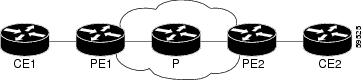
This feature allows you to transport Layer 2 Ethernet VLAN packets from various sources over an MPLS backbone. Ethernet over
MPLS extends the usability of the MPLS backbone by enabling it to offer Layer 2 services in addition to already existing Layer
3 services. You can enable the MPLS backbone network to accept Layer 2 VLAN packets by configuring the PE routers at the both
ends of the MPLS backbone.
In Cisco IOS XE Release 2.4, this feature was introduced on the Cisco ASR 1000 Series Routers.
In Cisco IOS XE Release 3.5S, support was added for the Cisco ASR 903 Router.
|
|
Any Transport over MPLS (AToM): Ethernet over MPLS: Port Mode (EoMPLS)
|
Cisco IOS XE Release 2.4
|
Ethernet over MPLS (EoMPLS) is the transport of Ethernet frames across an MPLS core. It transports all frames received on
a particular Ethernet or virtual LAN (VLAN) segment, regardless of the destination Media Access Control (MAC) information.
It does not perform MAC learning or MAC look up for forwarding packets from the Ethernet interface. Port mode allows a frame
coming into an interface to be packed into an MPLS packet and transported over the MPLS backbone to an egress interface.
In Cisco IOS XE Release 2.4, this feature was introduced on the Cisco ASR 1000 Series Routers.
|
|
Any Transport over MPLS-Ethernet over MPLS Enhancements: Fast Reroute
|
Cisco IOS XE Release 2.4
|
AToM can use MPLS traffic engineering (TE) tunnels with fast reroute (FRR) support. This features enhances FRR functionality
for Ethernet over MPLS (EoMPLS).
In Cisco IOS XE Release 2.4, this feature was introduced on the Cisco ASR 1000 Series Routers.
|
|
Any Transport over MPLS (AToM): Frame Relay over MPLS (FRoMPLS)
|
Cisco IOS XE Release 3.2.1S
|
In Cisco IOS XE Release 3.2.1S, this feature was introduced on the Cisco ASR 1000 Series Aggregation Services Routers.
This feature introduced no new or modified commands.
|
|
Any Transport over MPLS (AToM): HDLC over MPLS (HDLCoMPLS)
|
Cisco IOS XE Release 3.2S
|
In Cisco IOS XE Release 3.2S, this feature was introduced on the Cisco ASR 1000 Series Aggregation Services Routers.
This feature introduced no new or modified commands.
|
|
Any Transport over MPLS (AToM): Layer 2 Quality of Service (QoS)
|
Cisco IOS XE Release 2.3
|
This feature provides support for quality of service (QoS) features such as traffic policing, traffic shaping, packet marking,
and mapping of the packets.
In Cisco IOS XE Release 2.3, this feature was introduced on the Cisco ASR 1000 Series Routers.
|
|
Any Transport over MPLS (AToM): PPP over MPLS (PPPoMPLS)
|
Cisco IOS XE Release 3.2S
|
In Cisco IOS XE Release 3.2S, this feature was introduced on the Cisco ASR 1000 Series Aggregation Services Routers. This feature introduced no new or modified commands.
|
|
Any Transport over MPLS (AToM): Remote Ethernet Port Shutdown
|
Cisco IOS XE Release 2.4
|
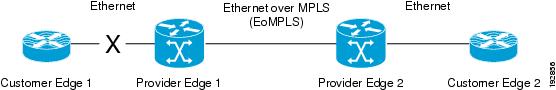
This feature allows a service provider edge (PE) router on the local end of an Ethernet over MPLS (EoMPLS) pseudowire to
detect a remote link failure and cause the shutdown of the Ethernet port on the local customer edge (CE) router. Because the
Ethernet port on the local CE router is shut down, the router does not lose data by continuously sending traffic to the failed
remote link. This is beneficial if the link is configured as a static IP route.
In Cisco IOS XE Release 2.4, this feature was introduced on the Cisco ASR 1000 Series Routers.
|
|
ATM Port Mode Packed Cell Relay over MPLS
|
Cisco IOS XE Release 3.5S
|
In Cisco IOS XE Release 3.5S, this feature was introduced on the Cisco ASR 1000 Series Aggregation Services Routers.
|
|
ATM VC Class Support
|
Cisco IOS XE Release 2.3
|
The ATM VC Class Support feature allows you to specify AAL5 and AAL0 encapsulations as part of a VC class.
In Cisco IOS XE Release 2.3, this feature was introduced on the Cisco ASR 1000 Series Routers.
|
|
AToM Tunnel Selection
|
Cisco IOS XE Release 2.3
|
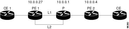
The AToM Tunnel Selection feature allows you to specify the path that traffic uses. You can specify either an MPLS TE tunnel
or destination IP address or domain name server (DNS) name.
You also have the option of specifying whether the VCs should use the default path (the path LDP uses for signaling) if the
preferred path is unreachable. This option is enabled by default; you must explicitly disable it.
In Cisco IOS XE Release 2.3, this feature was introduced on the Cisco ASR 1000 Series Aggregation Services Routers.
|
|
AToM: ATM Cell Relay over MPLS: VP Mode
|
Cisco IOS XE Release 2.3
|
The AToM: ATM Cell Relay over MPLS: VP Mode feature allows you to insert one ATM cell in each MPLS packet in VP mode.
In Cisco IOS XE Release 2.3, this feature was introduced on the Cisco ASR 1000 Series Routers.
|
|
AToM: Single Cell Relay-VC Mode
|
Cisco IOS XE Release 2.3
|
The AToM Single Cell Relay-VC Mode feature allows you to insert one ATM cell in each MPLS packet in VC mode.
In Cisco IOS XE Release 2.3, this feature was introduced on the Cisco ASR 1000 Series Routers.
|
|
MPLS MTU Command for GRE Tunnels
|
Cisco IOS XE Release 2.6
|
This feature allows you to set the MPLS MTU size in GRE tunnels to the maximum size besides the current default size.
The following command was modified for this release: mpls
mtu .
|
|
MPLS L2VPN Clear Xconnect Command
|
Cisco IOS XE Release 3.1S
|
These features enable you to:
-
Reset a VC associated with an interface, a peer address, or on all the configured xconnect circuit attachments
-
Set the control word on dynamic pseudowires (L2VPN pseudowire control word configuration
-
Enable ATM cell packing for static pseudowires.
The following commands were introduced or modified by these features: cell-packing , clear
xconnect , control-word , encapsulation (Any Transport over MPLS),
oam-ac
emulation-enable .
|
|
Per-Subinterface MTU for Ethernet over MPLS (EoMPLS)
|
Cisco IOS XE Release 2.4
|
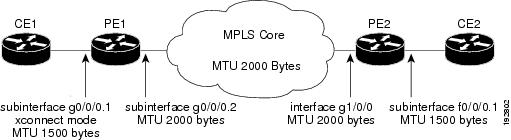
This feature provides you with the ability to specify maximum transmission unit (MTU) values in xconnect subinterface configuration
mode. When you use xconnect subinterface configuration mode to set the MTU value, you establish a pseudowire connection for
situations where the interfaces have different MTU values that cannot be changed.
In Cisco IOS XE Release 2.4, this feature was introduced on the Cisco ASR 1000 Series Aggregation Services Routers.
No commands were new or modified for this release.
|
|
VLAN ID Rewrite
|
Cisco IOS XE Release 2.4
|
The VLAN ID rewrite feature enables you to use VLAN interfaces with different VLAN IDs at both ends of the tunnel.
In Cisco IOS XE Release 2.4, this feature was introduced on the Cisco ASR 1000 Series Routers.
|
|
AToM Load Balancing with Single PW
|
Cisco IOS XE Release 3.4S
|
The AToM Load Balancing with Single PW feature enables load balancing for packets within the same pseudowire by further classifying
packets within the same pseudowire into different flows based on some field in the packet received on attachment circuit.
In Cisco IOS XE Release 3.4S, this feature was introduced on the Cisco ASR 1000 Series Aggregation Services Routers.
|
|
Flow-Aware Transport of MPLS Pseudowires
|
Cisco IOS XE Release 3.11S
|
The Flow-Aware Transport of MPLS Pseudowires feature enables load balancing of packets within the same pseudowire by further
classifying the packets into different flows by adding a flow label at the bottom of the MPLS label stack.
|
|
EoMPLS over IPv6 GRE Tunnel
|
Cisco IOS XE Release 3.15S
|
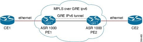
The EoMPLS over IPv6 GRE Tunnel feature supports tunneling of EoMPLS traffic via an IPv6 network by using GRE tunnels.
|

 Feedback