IP Multicast: Multicast Configuration Guide, Cisco IOS XE Release 3S (Cisco ASR 900 Series)
Bias-Free Language
The documentation set for this product strives to use bias-free language. For the purposes of this documentation set, bias-free is defined as language that does not imply discrimination based on age, disability, gender, racial identity, ethnic identity, sexual orientation, socioeconomic status, and intersectionality. Exceptions may be present in the documentation due to language that is hardcoded in the user interfaces of the product software, language used based on RFP documentation, or language that is used by a referenced third-party product. Learn more about how Cisco is using Inclusive Language.
This module describes
how to configure IPv6 Multicast PIM features.
Prerequisites for
IPv6 Multicast
The following are the prerequisites for IPv6 PIM source-specific
multicast (SSM):
Multicast
Listener Discovery (MLD) version 2 is required for source-specific multicast
(SSM) to operate.
Before
configuring SSM with MLD, SSM must be supported by the Cisco IPv6 device, the
host where the application is running, and the application itself.
Dynamic Domain
Name System (DNS) PIM Source Specific Multicast (SSM) mapping for multicast
Multicast Source
Discovery Protocol (MSDP)
Embedded RP is
not supported on RSP3 module.
Note
The Multicast
control packets are
not
processed when the system memory utilization is more than 90%. The following
message is displayed on the console.
*Sep 18 18:21:07.287: %SYS-2-NOMEMORY: No memory available for multicast control packets, dropping multicast control packets.
  Memory usage percentage:  91
The system
memory utilization may increase when the number of multicast sources and MLD
reports join rate is increased. When 90% of the system memory is used, the MLD
reports are
not
processed and multicast may not function as expected. For the multicast reports
to be processed again, decrease the join rate.
Information About IPv6 Multicast
IPv6 Multicast Routing Implementation
Cisco software supports the following protocols to implement IPv6 multicast routing:
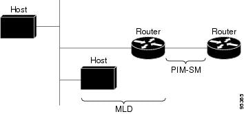
MLD is used by IPv6 devices to discover multicast listeners (nodes that want to receive multicast packets destined for specific
multicast addresses) on directly attached links. There are two versions of MLD:
MLD version 1 is based on version 2 of the Internet Group Management Protocol (IGMP) for IPv4.
MLD version 2 is based on version 3 of the IGMP for IPv4.
IPv6 multicast for Cisco software uses both MLD version 2 and MLD version 1. MLD version 2 is fully backward-compatible with
MLD version 1 (described in RFC 2710). Hosts that support only MLD version 1 will interoperate with a device running MLD version
2. Mixed LANs with both MLD version 1 and MLD version 2 hosts are likewise supported.
PIM-SM is used between devices so that they can track which multicast packets to forward to each other and to their directly
connected LANs.
PIM in Source Specific Multicast (PIM-SSM) is similar to PIM-SM with the additional ability to report interest in receiving
packets from specific source addresses (or from all but the specific source addresses) to an IP multicast address.
The figure below shows where MLD and PIM-SM operate within the IPv6 multicast environment.
Figure 1. IPv6 Multicast Routing Protocols Supported for IPv6
Protocol Independent Multicast
Protocol Independent Multicast (PIM) is used between devices so that they can track which multicast packets to forward to
each other and to their directly connected LANs. PIM works independently of the unicast routing protocol to perform send or
receive multicast route updates like other protocols. Regardless of which unicast routing protocols are being used in the
LAN to populate the unicast routing table, Cisco IOS PIM uses the existing unicast table content to perform the Reverse Path
Forwarding (RPF) check instead of building and maintaining its own separate routing table.
You can configure IPv6 multicast to use either a PIM- Sparse Mode (SM) or PIM-Source Specific Multicast (SSM) operation,
or you can use both PIM-SM and PIM-SSM together in your network.
PIM-Sparse Mode
IPv6 multicast provides support for intradomain multicast routing using PIM-SM. PIM-SM uses unicast routing to provide reverse-path
information for multicast tree building, but it is not dependent on any particular unicast routing protocol.
PIM-SM is used in a multicast network when relatively few devices are involved in each multicast and these devices do not
forward multicast packets for a group, unless there is an explicit request for the traffic. PIM-SM distributes information
about active sources by forwarding data packets on the shared tree. PIM-SM initially uses shared trees, which requires the
use of an RP.
Requests are accomplished via PIM joins, which are sent hop by hop toward the root node of the tree. The root node of a tree
in PIM-SM is the RP in the case of a shared tree or the first-hop device that is directly connected to the multicast source
in the case of a shortest path tree (SPT). The RP keeps track of multicast groups and the hosts that send multicast packets
are registered with the RP by that host’s first-hop device.
As a PIM join travels up the tree, devices along the path set up multicast forwarding state so that the requested multicast
traffic will be forwarded back down the tree. When multicast traffic is no longer needed, a device sends a PIM prune up the
tree toward the root node to prune (or remove) the unnecessary traffic. As this PIM prune travels hop by hop up the tree,
each device updates its forwarding state appropriately. Ultimately, the forwarding state associated with a multicast group
or source is removed.
A multicast data sender sends data destined for a multicast group. The designated router (DR) of the sender takes those data
packets, unicast-encapsulates them, and sends them directly to the RP. The RP receives these encapsulated data packets, de-encapsulates
them, and forwards them onto the shared tree. The packets then follow the (*, G) multicast tree state in the devices on the
RP tree, being replicated wherever the RP tree branches, and eventually reaching all the receivers for that multicast group.
The process of encapsulating data packets to the RP is called registering, and the encapsulation packets are called PIM register
packets.
Designated Router
Cisco devices use
PIM-SM to forward multicast traffic and follow an election process to select a
designated device when there is more than one device on a LAN segment.
The designated router
(DR) is responsible for sending PIM register and PIM join and prune messages
toward the RP to inform it about active sources and host group membership.
If there are multiple
PIM-SM devices on a LAN, a DR must be elected to avoid duplicating multicast
traffic for connected hosts. The PIM device with the highest IPv6 address
becomes the DR for the LAN unless you choose to force the DR election by use of
theipv6pimdr-priority command. This command allows you to
specify the DR priority of each device on the LAN segment (default priority =
1) so that the device with the highest priority will be elected as the DR. If
all devices on the LAN segment have the same priority, then the highest IPv6
address is again used as the tiebreaker.
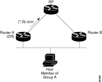
The figure below
illustrates what happens on a multiaccess segment. Device A and Device B are
connected to a common multiaccess Ethernet segment with Host A as an active
receiver for Group A. Only Device A, operating as the DR, sends joins to the RP
to construct the shared tree for Group A. If Device B was also permitted to
send (*, G) joins to the RP, parallel paths would be created and Host A would
receive duplicate multicast traffic. Once Host A begins to source multicast
traffic to the group, the DR’s responsibility is to send register messages to
the RP. If both devices were assigned the responsibility, the RP would receive
duplicate multicast packets and result in wastage of bandwidth.
Figure 2. Designated Router Election on
a Multiaccess Segment
If the DR should
fail, the PIM-SM provides a way to detect the failure of Device A and elect a
failover DR. If the DR (Device A) became inoperable, Device B would detect this
situation when its neighbor adjacency with Device A timed out. Because Device B
has been hearing MLD membership reports from Host A, it already has MLD state
for Group A on this interface and would immediately send a join to the RP when
it became the new DR. This step reestablishes traffic flow down a new branch of
the shared tree via Device B. Additionally, if Host A were sourcing traffic,
Device B would initiate a new register process immediately after receiving the
next multicast packet from Host A. This action would trigger the RP to join the
SPT to Host A via a new branch through Device B.
Tip
Two PIM devices are
neighbors if there is a direct connection between them. To display your PIM
neighbors, use the
showipv6pimneighbor command in privileged EXEC mode.
Note
The DR election
process is required only on multiaccess LANs.
Rendezvous Point
Note
Embedded RP is not
supported on Cisco RSP3 Module.
IPv6 PIM provides
embedded RP support. Embedded RP support allows the device to learn RP
information using the multicast group destination address instead of the
statically configured RP. For devices that are the RP, the device must be
statically configured as the RP.
The device searches
for embedded RP group addresses in MLD reports or PIM messages and data
packets. On finding such an address, the device learns the RP for the group
from the address itself. It then uses this learned RP for all protocol activity
for the group. For devices that are the RP, the device is advertised as an
embedded RP must be configured as the RP.
To select a static RP
over an embedded RP, the specific embedded RP group range or mask must be
configured in the access list of the static RP. When PIM is configured in
sparse mode, you must also choose one or more devices to operate as an RP. An
RP is a single common root placed at a chosen point of a shared distribution
tree and is configured statically in each box.
PIM DRs forward data
from directly connected multicast sources to the RP for distribution down the
shared tree. Data is forwarded to the RP in one of two ways:
Data is
encapsulated in register packets and unicast directly to the RP by the
first-hop device operating as the DR.
If the RP has
itself joined the source tree, it is multicast-forwarded per the RPF forwarding
algorithm described in the PIM-Sparse Mode section.
The RP address is
used by first-hop devices to send PIM register messages on behalf of a host
sending a packet to the group. The RP address is also used by last-hop devices
to send PIM join and prune messages to the RP to inform it about group
membership. You must configure the RP address on all devices (including the RP
device).
A PIM device can be
an RP for more than one group. Only one RP address can be used at a time within
a PIM domain for a certain group. The conditions specified by the access list
determine for which groups the device is an RP.
IPv6 multicast
supports the PIM accept register feature, which is the ability to perform
PIM-SM register message filtering at the RP. The user can match an access list
or compare the AS path for the registered source with the AS path specified in
a route map.
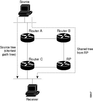
PIM Shared Tree and Source Tree (Shortest-Path Tree)
By default, members of a group receive data from senders to the group across a single data distribution tree rooted at the
RP. This type of distribution tree is called shared tree or rendezvous point tree (RPT), as illustrated in the figure below.
Data from senders is delivered to the RP for distribution to group members joined to the shared tree.
Figure 3. Shared Tree and Source Tree (Shortest Path Tree)
If the data threshold warrants, leaf devices on the shared tree may initiate a switch to the data distribution tree rooted
at the source. This type of distribution tree is called a shortest path tree or source tree. By default, the software switches
to a source tree upon receiving the first data packet from a source.
The following process details the move from shared tree to source tree:
Receiver joins a group; leaf Device C sends a join message toward the RP.
RP puts the link to Device C in its outgoing interface list.
Source sends the data; Device A encapsulates the data in the register and sends it to the RP.
RP forwards the data down the shared tree to Device C and sends a join message toward the source. At this point, data may
arrive twice at Device C, once encapsulated and once natively.
When data arrives natively (unencapsulated) at the RP, the RP sends a register-stop message to Device A.
By default, receipt of the first data packet prompts Device C to send a join message toward the source.
When Device C receives data on (S, G), it sends a prune message for the source up the shared tree.
RP deletes the link to Device C from the outgoing interface of (S, G).
RP triggers a prune message toward the source.
Join and prune messages are sent for sources and RPs. They are sent hop-by-hop and are processed by each PIM device along
the path to the source or RP. Register and register-stop messages are not sent hop-by-hop. They are sent by the designated
router (DR) that is directly connected to a source and are received by the RP for the group.
Reverse Path
Forwarding
Reverse-path
forwarding is used for forwarding multicast datagrams. It functions as follows:
If a device
receives a datagram on an interface it uses to send unicast packets to the
source, the packet has arrived on the RPF interface.
If the packet
arrives on the RPF interface, a device forwards the packet out the interfaces
present in the outgoing interface list of a multicast routing table entry.
If the packet
does not arrive on the RPF interface, the packet is silently discarded to
prevent loops.
PIM uses both source
trees and RP-rooted shared trees to forward datagrams; the RPF check is
performed differently for each, as follows:
If a PIM device
has source-tree state (that is, an (S, G) entry is present in the multicast
routing table), the device performs the RPF check against the IPv6 address of
the source of the multicast packet.
If a PIM device
has shared-tree state (and no explicit source-tree state), it performs the RPF
check on the RP’s address (which is known when members join the group).
Sparse-mode PIM uses
the RPF lookup function to determine where it needs to send joins and prunes.
(S, G) joins (which are source-tree states) are sent toward the source. (*, G)
joins (which are shared-tree states) are sent toward the RP.
Note
To do a RPF check, use the
show ipv6 rpf hostname or
show ipv6 rpf vrf vrf_name hostname command.
PIM IPv6 Stub
Routing
The PIM stub routing
feature reduces resource usage by moving routed traffic closer to the end user.
In a network using PIM
stub routing, the only allowable route for IPv6 traffic to the user is through
a switch that is configured with PIM stub routing. PIM passive interfaces are
connected to Layer 2 access domains, such as VLANs, or to interfaces that are
connected to other Layer 2 devices. Only directly connected multicast receivers
and sources are allowed in the Layer 2 access domains. The PIM passive
interfaces do not send or process any received PIM control packets.
When using PIM stub
routing, you should configure the distribution and remote routers to use IPv6
multicast routing and configure only the switch as a PIM stub router. The
switch does not route transit traffic between distribution routers. You also
need to configure a routed uplink port on the switch. The switch uplink port
cannot be used with SVIs.
You must also configure EIGRP stub routing when configuring PIM stub routing on the switch.
The redundant PIM stub
router topology is not supported. The redundant topology exists when there is
more than one PIM router forwarding multicast traffic to a single access
domain. PIM messages are blocked, and the PIM assert and designated router
election mechanisms are not supported on the PIM passive interfaces. Only the
non-redundant access router topology is supported by the PIM stub feature. By
using a non-redundant topology, the PIM passive interface assumes that it is
the only interface and designated router on that access domain.
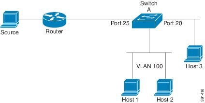
In the figure shown below, Switch A routed uplink port 25 is connected to the router and PIM stub routing is enabled on the
VLAN 100 interfaces and on Host 3. This configuration allows the directly connected hosts to receive traffic from multicast
source.
Figure 4. PIM Stub Router
Configuration
MRIB
The Multicast Routing Information Base (MRIB) is a
protocol-independent repository of multicast routing entries
instantiated by multicast routing protocols (routing clients). Its
main function is to provide independence between routing protocols
and the Multicast Forwarding Information Base (MFIB). It also acts
as a coordination and communication point among its clients.
Routing clients use the services provided by the MRIB to
instantiate routing entries and retrieve changes made to routing
entries by other clients. Besides routing clients, MRIB also has
forwarding clients (MFIB instances) and special clients such as
MLD. MFIB retrieves its forwarding entries from MRIB and notifies
the MRIB of any events related to packet reception. These
notifications can either be explicitly requested by routing clients
or spontaneously generated by the MFIB.
Another important function of the MRIB is to allow for the
coordination of multiple routing clients in establishing multicast
connectivity within the same multicast session. MRIB also allows
for the coordination between MLD and routing protocols.
MFIB
The MFIB is a platform-independent and routing-protocol-independent
library for IPv6 software. Its main purpose is to provide a Cisco
IOS platform with an interface with which to read the IPv6
multicast forwarding table and notifications when the forwarding
table changes. The information provided by the MFIB has clearly
defined forwarding semantics and is designed to make it easy for
the platform to translate to its specific hardware or software
forwarding mechanisms.
When routing or topology changes occur in the network, the IPv6
routing table is updated, and those changes are reflected in the
MFIB. The MFIB maintains next-hop address information based on the
information in the IPv6 routing table. Because there is a
one-to-one correlation between MFIB entries and routing table
entries, the MFIB contains all known routes and eliminates the need
for route cache maintenance that is associated with switching paths
such as fast switching and optimum switching.
MFIB
Note
Distributed MFIB
has its significance only in a stacked environment where the Master distributes
the MFIB information to the other stack members. In the following section the
line cards are nothing but the member switches in the stack.
MFIB (MFIB) is used to switch
multicast IPv6 packets on distributed platforms.
MFIB may also contain
platform-specific information on replication across line cards. The basic MFIB
routines that implement the core of the forwarding logic are common to all
forwarding environments.
MFIB implements the
following functions:
Relays data-driven
protocol events generated in the line cards to PIM.
Provides an MFIB
platform application program interface (API) to propagate MFIB changes to
platform-specific code responsible for programming the hardware acceleration
engine. This API also includes entry points to switch a packet in software
(necessary if the packet is triggering a data-driven event) and to upload
traffic statistics to the software.
The combination of
MFIB and MRIB
subsystems also allows the switch to have a "customized" copy of the MFIB
database in each line card and to transport MFIB-related platform-specific
information from the RP to the line cards.
IPv6 Multicast
Process Switching and Fast Switching
A unified MFIB is used
to provide both fast switching and process switching support for PIM-SM and
PIM-SSM in IPv6 multicast. In process switching, the
must examine,
rewrite, and forward each packet. The packet is first received and copied into
the system memory. The switch then looks up the Layer 3 network address in the
routing table. The Layer 2 frame is then rewritten with the next-hop
destination address and sent to the outgoing interface. The
also computes the
cyclic redundancy check (CRC). This switching method is the least scalable
method for switching IPv6 packets.
IPv6 multicast fast
switching allows switches to provide better packet forwarding performance than
process switching. Information conventionally stored in a route cache is stored
in several data structures for IPv6 multicast switching. The data structures
provide optimized lookup for efficient packet forwarding.
In IPv6 multicast
forwarding, the first packet is fast-switched if the PIM protocol logic allows
it. In IPv6 multicast fast switching, the MAC encapsulation header is
precomputed. IPv6 multicast fast switching uses the MFIB to make IPv6
destination prefix-based switching decisions. In addition to the MFIB, IPv6
multicast fast switching uses adjacency tables to prepend Layer 2 addressing
information. The adjacency table maintains Layer 2 next-hop addresses for all
MFIB entries.
The adjacency table is
populated as adjacencies are discovered. Each time an adjacency entry is
created (such as through ARP), a link-layer header for that adjacent node is
precomputed and stored in the adjacency table. Once a route is determined, it
points to a next hop and corresponding adjacency entry. It is subsequently used
for encapsulation during switching of packets.
A route might have
several paths to a destination prefix, such as when a switch is configured for
simultaneous load balancing and redundancy. For each resolved path, a pointer
is added for the adjacency corresponding to the next-hop interface for that
path. This mechanism is used for load balancing across several paths.
Enabling IPv6
Multicast Routing
Beginning in
privileged EXEC mode, follow these steps:
Procedure
Command or Action
Purpose
Step 1
configureterminal
Enter global
configuration mode.
Step 2
ipv6 multicast-routing
Example:
(config)# ipv6 multicast-routing
Enables
multicast routing on all IPv6-enabled interfaces and enables multicast
forwarding for PIM and MLD on all enabled interfaces of the switch.
Step 3
copy running-config startup-config
(Optional) Save
your entries in the configuration file.
IPv6 Multicast: PIM Sparse
Mode
IPv6 multicast provides support for intradomain multicast routing using
PIM sparse mode (PIM-SM). PIM-SM uses unicast routing to provide reverse-path
information for multicast tree building, but it is not dependent on any
particular unicast routing protocol.
IPv6 PIM Passive
Mode
A device configured
with PIM will always send out PIM hello messages to all interfaces enabled for
IPv6 multicast routing, even if the device is configured not to accept PIM
messages from any neighbor on the LAN.
IPv6 Multicast: PIM
Source-Specific Multicast
The PIM source-specific multicast (SSM) routing protocol supports SSM
implementation and is derived from PIM-SM. However, unlike PIM-SM data from all
multicast sources are sent when there is a PIM join, the SSM feature forwards
datagram traffic to receivers from only those multicast sources that the
receivers have explicitly joined, thus optimizing bandwidth utilization and
denying unwanted Internet broadcast traffic.
IPv6 Source Specific Multicast Mapping
SSM mapping for IPv6 supports both static and dynamic Domain Name System (DNS) mapping for MLD version 1 receivers. This
feature allows deployment of IPv6 SSM with hosts that are incapable of providing MLD version 2 support in their TCP/IP host
stack and their IP multicast receiving application. SSM mapping allows the device to look up the source of a multicast MLD
version 1 report either in the running configuration of the device or from a DNS server. The device can then initiate an (S,
G) join toward the source.
How to Configure IPv6 Multicast
Enabling IPv6 Multicast Routing
IPv6 multicast uses MLD version 2. This version of MLD is fully backward-compatible with MLD version 1 (described in
RFC 2710). Hosts that support only MLD version 1 will interoperate with a device running MLD version 2. Mixed LANs with both MLD version
1 and MLD version 2 hosts are likewise supported.
Before you begin
You must first enable IPv6 unicast routing on all interfaces of the device on which you want to enable IPv6 multicast routing
.
SUMMARY STEPS
enable
configureterminal
ipv6multicast-routing[vrfvrf-name]
DETAILED STEPS
Command or Action
Purpose
Step 1
enable
Example:
Device> enable
Enables privileged EXEC mode.
Enter your password if prompted.
Step 2
configureterminal
Example:
Device# configure terminal
Enters global configuration mode.
Step 3
ipv6multicast-routing[vrfvrf-name]
Example:
Device(config)# ipv6 multicast-routing
Enables multicast routing on all IPv6-enabled interfaces and enables multicast forwarding for PIM and MLD on all enabled
interfaces of the device.
IPv6 multicast routing is disabled by default when IPv6 unicast routing is enabled. IPv6 multicast-routing needs to be enabled
for IPv6 multicast routing to function.
If PIM malfunctions, or in order to verify that the expected number of PIM packets are received and sent, clear PIM traffic
counters. Once the traffic counters are cleared, you can verify that PIM is functioning correctly and that PIM packets are
being received and sent correctly.
SUMMARY STEPS
enable
clearipv6pim[vrfvrf-name]
traffic
showipv6pim [vrfvrf-name]
traffic
DETAILED STEPS
Command or Action
Purpose
Step 1
enable
Example:
Device> enable
Enables privileged EXEC mode.
Enter your password if prompted.
Step 2
clearipv6pim[vrfvrf-name]
traffic
Example:
Device# clear ipv6 pim traffic
Resets the PIM traffic counters.
Step 3
showipv6pim [vrfvrf-name]
traffic
Example:
Device# show ipv6 pim traffic
Displays the PIM traffic counters.
Clearing the PIM Topology Table to Reset the MRIB Connection
No configuration is necessary to use the MRIB. However, users may in certain situations want to clear the PIM topology table
in order to reset the MRIB connection and verify MRIB information.
Displays information about MRIB routing entry-related activity.
Step 10
debugipv6mrib[vrfvrf-name]
table
Example:
Device# debug ipv6 mrib table
Enables debugging on MRIB table management activity.
Turning Off IPv6 PIM
on a Specified Interface
A user might want
only specified interfaces to perform IPv6 multicast and will therefore want to
turn off PIM on a specified interface.
Note
Though IOS
supports disabling PIM on an interface, this is not possible on RSP3 platform
due to caveat. Ipv6 multicast packets will still get punted to CPU even if PIM
is turned off on the interface.
SUMMARY STEPS
enable
configureterminal
interfacetypenumber
noipv6pim
DETAILED STEPS
Command or Action
Purpose
Step 1
enable
Example:
Device> enable
Enables privileged EXEC mode.
Enter your password if prompted.
Step 2
configureterminal
Example:
Device# configure terminal
Enters global configuration mode.
Step 3
interfacetypenumber
Example:
Device(config)# interface gigabitethernet 0/1/0
Specifies an
interface type and number, and places the device in interface configuration
mode.
Step 4
noipv6pim
Example:
Device(config-if)# no ipv6 pim
Turns off IPv6 PIM on a specified interface.
Disabling Embedded RP Support in IPv6 PIM
A user might want to disable embedded RP support on an interface if all of the devices in the domain do not support embedded
RP.
Note
This task disables PIM completely, not just embedded RP support in IPv6 PIM.
SUMMARY STEPS
enable
configureterminal
noipv6pim [vrfvrf-name]
rpembedded
interfacetypenumber
noipv6pim
DETAILED STEPS
Command or Action
Purpose
Step 1
enable
Example:
Device> enable
Enables privileged EXEC mode.
Enter your password if prompted.
Step 2
configureterminal
Example:
Device# configure terminal
Enters global configuration mode.
Step 3
noipv6pim [vrfvrf-name]
rpembedded
Example:
Device(config)# no ipv6 pim rp embedded
Disables embedded RP support in IPv6 PIM.
Step 4
interfacetypenumber
Example:
Device(config)# interface gigabitethernet 0/1/0
Specifies an
interface type and number, and places the device in interface configuration
mode.
Step 5
noipv6pim
Example:
Device(config-if)# no ipv6 pim
Turns off IPv6 PIM on a specified interface.
Configuring IPv6 SSM
When the SSM
mapping feature is enabled, DNS-based SSM mapping is automatically enabled,
which means that the device will look up the source of a multicast MLD version
1 report from a DNS server.
You can configure
either DNS-based or static SSM mapping, depending on your device configuration.
If you choose to use static SSM mapping, you can configure multiple static SSM
mappings. If multiple static SSM mappings are configured, the source addresses
of all matching access lists will be used.
Before you begin
Note
To use
DNS-based SSM mapping, the device needs to find at least one correctly
configured DNS server to which the device can be directly attached.
Enables the PIM passive feature on an IPv6 device.
Step 4
ipv6mldstate-limitnumber
Example:
Device(config)# ipv6 mld state-limit 100
(Optional)
Specifies maximum number of dynamic MLD groups allowed on a router.
Step 5
interfacetypenumber
Example:
Device(config)# interface GigabitEthernet 1/0/0
Specifies an interface type and number, and places the device in interface configuration mode.
Step 6
ipv6pimpassive
Example:
Device(config-if)# ipv6 pim passive
Enables the PIM passive feature on a specific interface.
Step 7
ipv6mldlimitnumber
Example:
Device(config-if)# ipv6 mld limit 300
(Optional)
Configure the per-interface MLD state limit. You can use this command to limit
the dynamic MLD groups joined.
Step 8
noipv6mldrouter
Example:
Device(config-if)# no ipv6 mld router
(Optional)
Prevents the interface from processing MLD v1/v2 joins sent through it or to
prune from a group it has already joined. To enable the interface to start
receiving MLD reports again, use
ipv6 mld
router command.
Step 9
showipv6mldinterface
Example:
Device(config-if)# show ipv6 mld interface 1/0/0
(Optional)
Displays MLD information about the interface. You can use this command to
determine which interface acts as a querier.
Configuring a BSR
The tasks included here are described below.
Configuring a BSR
and Verifying BSR Information
Beginning in
privileged EXEC mode, follow these steps:
The following example displays RPF information for the unicast host with the IPv6
address of
2001:DB8:1:1:2:
Router# show ipv6 rpf 2001:DB8:1:1:2
RPF information for 2001:DB8:1:1:2
  RPF interface:GigabitEthernet3/2/0
  RPF neighbor:FE80::40:1:3
  RPF route/mask:20::/64
  RPF type:Unicast
  RPF recursion count:0
  Metric preference:110
  Metric:30
Example: Enabling IPv6 Multicast Routing
The following example enables multicast routing on all interfaces and also enables multicast forwarding for PIM and MLD on
all enabled interfaces of the device.
The following example shows how to configure a device to use PIM-SM using 2001:DB8::1 as the RP. It sets the SPT threshold
to infinity to prevent switchover to the source tree when a source starts sending traffic and sets a filter on all sources
that do not have a local multicast BGP prefix.
Example: Displaying
PIM-SM Information for a Group Range
This example displays information about interfaces configured for PIM:
Device# show ipv6 pim interface state-on

Interface          PIM   Nbr   Hello  DR
                         Count Intvl  Prior

Gi0/1/2            on    0     30     1
    Address: FE80::D2C2:82FF:FE17:F392
    DR     : this system
Gi0/1/5            on    1     30     1
    Address: FE80::D2C2:82FF:FE17:F395
    DR     : FE80::D2C2:82FF:FE17:FAA5
Loopback0          on    0     30     1
    Address: FE80::D2C2:82FF:FE17:F380
    DR     : this system
This example displays an IPv6 multicast group mapping table:
Device# show ipv6 pim group-map

FF33::/32*
      SSM
      Info source:Static
      Uptime:00:08:32, Groups:0
  FF34::/32*
      SSM
      Info source:Static
      Uptime:00:09:42, Groups:0
This example displays information about IPv6 multicast range lists:
Device# show ipv6 pim range-list

config SSM Exp:never Learnt from :::
 FF33::/32 Up:00:26:33
 FF34::/32 Up:00:26:33
 FF35::/32 Up:00:26:33
 FF36::/32 Up:00:26:33
 FF37::/32 Up:00:26:33
 FF38::/32 Up:00:26:33
 FF39::/32 Up:00:26:33
 FF3A::/32 Up:00:26:33
 FF3B::/32 Up:00:26:33
 FF3C::/32 Up:00:26:33
 FF3D::/32 Up:00:26:33
 FF3E::/32 Up:00:26:33
 FF3F::/32 Up:00:26:33
config SM RP:40::1:1:1 Exp:never Learnt from :::
 FF13::/64 Up:00:03:50
config SM RP:40::1:1:3 Exp:never Learnt from :::
 FF09::/64 Up:00:03:50
Example: Displaying
IPv6 PIM Topology Information
Device# show ipv6 pim topology

IP PIM Multicast Topology Table
Entry state: (*/S,G)[RPT/SPT] Protocol Uptime Info Upstream Mode
Entry flags: KAT - Keep Alive Timer, AA - Assume Alive, PA - Probe Alive,
    RA - Really Alive, LH - Last Hop, DSS - Don't Signal Sources,
    RR - Register Received, SR - Sending Registers, E - MSDP External,
    DCC - Don't Check Connected, Y - Joined MDT-data group,
    y - Sending to MDT-data group
    BGS - BGP Signal Sent, !BGS - BGP signal suppressed
    SAS - BGP Src-Act Sent, SAR - BGP Src-Act Received
Interface state: Name, Uptime, Fwd, Info
Interface flags: LI - Local Interest, LD - Local Disinterest,
    II - Internal Interest, ID - Internal Disinterest,
    LH - Last Hop, AS - Assert, AB - Admin Boundary, BS - BGP Signal,
    BP - BGP Shared-Tree Prune, BPT - BGP Prune Time

(*,FF08::1)
SM UP: 00:04:36 JP: Join(00:00:28) Flags:
RP: 8001::1*
RPF: Tunnel1,8001::1*
  Gi0/1/5            00:04:36  fwd     Join(00:03:01)

(3001::5,FF08::1)
SM SPT UP: 00:04:57 JP: Join(never) Flags: KAT(00:02:12) RA
RPF: GigabitEthernet0/1/2,3001::5*
  Gi0/1/5            00:04:36  fwd     Join(00:03:01)
Property
Type
Property Value
Property
Description
Example: Displaying Information About PIM Traffic
Device# show ipv6 pim traffic

PIM Traffic Counters
Elapsed time since counters cleared:00:05:29

                              Received     Sent
Valid PIM Packets               22          22
Hello                           22          22
Join-Prune                      0           0
Register                        0           0
Register Stop                   0           0
Assert                          0           0
Bidir DF Election               0           0

Errors:
Malformed Packets                           0
Bad Checksums                               0
Send Errors                                 0
Packet Sent on Loopback Errors              0
Packets Received on PIM-disabled Interface  0
Packets Received with Unknown PIM Version   0
Example: Disabling Embedded RP Support in IPv6 PIM
The following example disables embedded RP support on IPv6 PIM:
Device(config)# ipv6 multicast-routing
Device(config)# no ipv6 pim rp embedded
Example: IPv6 SSM Mapping
Device# show ipv6 mld ssm-map 2001:DB8::1

 Group address  : 2001:DB8::1
 Group mode ssm : TRUE
 Database       : STATIC
 Source list    : 2001:DB8::2
                  2001:DB8::3

Device# show ipv6 mld ssm-map 2001:DB8::2

 Group address  : 2001:DB8::2
 Group mode ssm : TRUE
 Database       : DNS
 Source list    : 2001:DB8::3
                  2001:DB8::1


 Feedback