- Preface
- Introduction
- Overview of SPA Interface Processors
- Overview of Shared Port Adapters
- Packing SIP and SPA for Shipment
- Unpacking SIP and SPA
- Preparing to Install a SIP or a SPA
- Installing and Removing a SPA Interface Processor
- Installing and Removing a Shared Port Adapter
- Verifying and Troubleshooting SIPs and SPAs
Cisco uBR10012 Universal Broadband Router SIP and SPA Hardware Installation Guide
Bias-Free Language
The documentation set for this product strives to use bias-free language. For the purposes of this documentation set, bias-free is defined as language that does not imply discrimination based on age, disability, gender, racial identity, ethnic identity, sexual orientation, socioeconomic status, and intersectionality. Exceptions may be present in the documentation due to language that is hardcoded in the user interfaces of the product software, language used based on RFP documentation, or language that is used by a referenced third-party product. Learn more about how Cisco is using Inclusive Language.
- Updated:
- September 4, 2014
Chapter: Installing and Removing a SPA Interface Processor
Installing and Removing a SPA Interface Processor
Online Insertion and Removal
The Cisco uBR10012 router supports online insertion and removal (OIR) of the SPA interface processor (SIP) and of the shared port adapters (SPAs). Therefore, you can remove a SIP with its SPAs still intact, or you can remove a SPA independently from the SIP, leaving the SIP installed in the router.
If you are replacing the SPA after a duration of three months, perform a field upgrade of the SPA. Do not perform an OIR. For more information on field upgrade, see Field Upgrade of the SPA.
 Note | If the SIP is running normally in chassis, SPA cards can be installed and removed directly from SIP without installing SIP. |
Preparing for Online Removal of a SIP
See “Preparing for Online Removal of a SIP” section in the Cisco uBR10012 Universal Broadband Router SIP and SPA Software Configuration Guide.
For more information about the recommended procedures for physical removal of the SIP, see SIP Installation and Removal chapter.
Handling SIPs
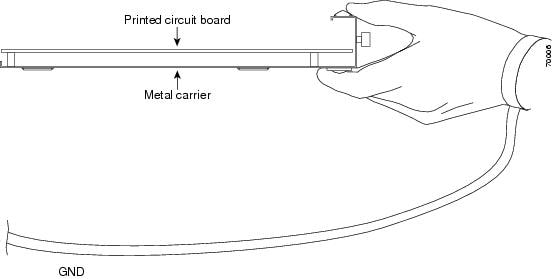
Each SIP circuit board is mounted to a metal carrier and is sensitive to electrostatic discharge (ESD) damage. Before you begin installation, see Required Tools and Equipments section for a list of parts and tools required for installation.
 Caution | Always handle the SIP by the carrier edges; never touch the SIP components or connector pins. |
When a slot is not in use, a blank filler plate must be installed in the empty slot to allow the router or switch to conform to electromagnetic interference (EMI) emissions requirements and to allow proper airflow across the installed modules. If you plan to install a SIP in a slot that is not in use, you must first remove the two blank filler plates.
 Caution | The Cisco Wideband SIP and Cisco SIP-600 each weigh 10 lb. Use both hands while handling the SIPs. |
SIP Installation and Removal
Installing SIP
 Warning | When performing the following procedures, wear a grounding wrist strap to avoid ESD damage to the SIP. Some platforms have an ESD connector for attaching the wrist strap. Do not directly touch the midplane or backplane with your hand or any metal tool, or you could receive an electrical shock. |
Ensure that you remove any existing line card configuration from the SIP slots.
| Step 1 |
Attach a grounding wrist strap to your wrist and to a bare metal surface on the chassis or frame.
| ||||
| Step 2 |
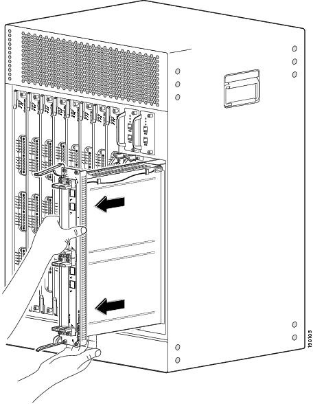
Grasp the faceplate of the SIP with one hand and place your other hand under the SIP (to support the weight of the SIP) and position the SIP in front of the appropriate card cage slot.
| ||||
| Step 3 |
Carefully align the upper and lower guides on the SIP with the upper and lower guides in the chassis and slide the SIP into the module slot until you can feel it begin to seat in the backplane connectors. | ||||
| Step 4 |
Simultaneously pivot both SIP ejector levers toward each other (until they are parallel to the faceplate) to firmly seat the SIP in the router backplane. 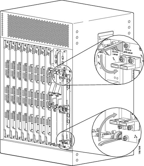
| ||||
| Step 5 |
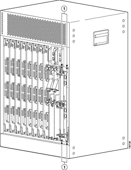
Tighten the top and bottom captive screws on the SIP to secure it in the chassis. | ||||
| Step 6 |
If needed, install the SPAs. See Installing a SPA in a SIP section. | ||||
| Step 7 |
Install the interface cables. We recommend that you clean the fiber-optic connections before attaching the cables. See the Inspection and Cleaning Procedures for Fiber-Optic Connections document. |
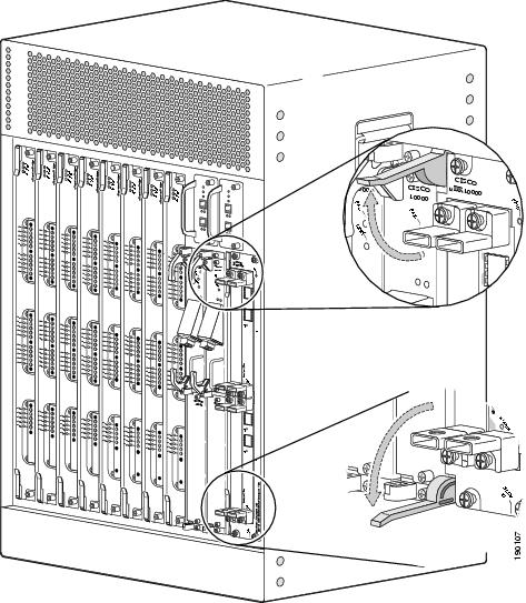
Removing SIP
 Tip | To prevent alarms from activating, you can administratively shut down a SIP before hot-swapping it. Otherwise, inform the network administrator that this portion of the network will be temporarily interrupted. |
 Warning | When performing the following procedures, wear a grounding wrist strap to avoid ESD damage to the SIP. Some platforms have an ESD connector for attaching the wrist strap. Do not directly touch the midplane or backplane with your hand or any metal tool, or you could shock yourself. |
 Feedback