- Preface
- Configuration Quick Reference
- Cisco Services Ready Engine Virtualization Overview
- Installing and Managing the Cisco SRE-V Software
- Installing the Cisco SRE Service Module into the Router
- Configuring the Cisco SRE Service Module Interfaces
- Managing the Cisco SRE-V Software Licenses
- Managing Virtual Machines
- Managing RAID
- Recovering from Device or Software Failure
- Index
Installation and Configuration Guide for Cisco Services Ready Engine Virtualization 1.5
Bias-Free Language
The documentation set for this product strives to use bias-free language. For the purposes of this documentation set, bias-free is defined as language that does not imply discrimination based on age, disability, gender, racial identity, ethnic identity, sexual orientation, socioeconomic status, and intersectionality. Exceptions may be present in the documentation due to language that is hardcoded in the user interfaces of the product software, language used based on RFP documentation, or language that is used by a referenced third-party product. Learn more about how Cisco is using Inclusive Language.
- Updated:
- November 4, 2010
Chapter: Configuring the Cisco SRE Service Module Interfaces
- Basic Workflow for Configuring the Cisco SRE Service Module Interfaces
- Cisco SRE Service Module Interfaces Overview
- Configuring the Cisco SRE Service Module Interfaces
Configuring the Cisco SRE Service Module Interfaces
This chapter provides information about how to configure the Cisco SRE Service Module interfaces to run the Cisco SRE-V System software.
Before you begin, make sure that the ISR G2 in which the Cisco SRE Service Module is installed is running the supported Cisco IOS software version. See the "Verifying the Router, Cisco SRE Service Module, and Cisco IOS Software Version Compatibility" section on page 2-2.
This chapter contains the following sections:
•![]() Basic Workflow for Configuring the Cisco SRE Service Module Interfaces
Basic Workflow for Configuring the Cisco SRE Service Module Interfaces
•![]() Cisco SRE Service Module Interfaces Overview
Cisco SRE Service Module Interfaces Overview
•![]() Configuring the Cisco SRE Service Module Interfaces
Configuring the Cisco SRE Service Module Interfaces
•![]() Reload, Reset, and Shut Down Commands
Reload, Reset, and Shut Down Commands
Basic Workflow for Configuring the Cisco SRE Service Module Interfaces
1. ![]() Configure sm1/0 of the VMware vSphere HypervisorTM.
Configure sm1/0 of the VMware vSphere HypervisorTM.
2. ![]() Configure sm1/1 of the VMware vSphere HypervisorTM.
Configure sm1/1 of the VMware vSphere HypervisorTM.
3. ![]() Configure VLANs.
Configure VLANs.
See the "Configuring the Cisco SRE Service Module Interfaces on the Router" section.
Cisco SRE Service Module Interfaces Overview
The host router and the Cisco SRE Service Module use several interfaces for internal and external communication. Use the Cisco IOS CLI commands to configure each of the interfaces on the router.
Before configuring the interfaces, make sure that you have the following information for entering the Cisco SRE Service Module command environment:
•![]() IP address of the Cisco router that contains the Cisco SRE Service Module.
IP address of the Cisco router that contains the Cisco SRE Service Module.
•![]() Username and password for logging into the router.
Username and password for logging into the router.
•![]() Slot and unit number of the Cisco SRE Service Module.
Slot and unit number of the Cisco SRE Service Module.
The Cisco SRE Service Module communicates with the host router through the following three interfaces:
•![]() Console Interface—Console interface allows you to access the VMware vSphere HypervisorTM Direct Console User Interface (DCUI) to perform Cisco SRE-V configuration. Accessible from within the host router, this interface provides an internal Layer 3 Gigabit Ethernet link between the router and the Cisco SRE Service Module. All configuration and management of the console interface is performed using the Cisco IOS CLI.
Console Interface—Console interface allows you to access the VMware vSphere HypervisorTM Direct Console User Interface (DCUI) to perform Cisco SRE-V configuration. Accessible from within the host router, this interface provides an internal Layer 3 Gigabit Ethernet link between the router and the Cisco SRE Service Module. All configuration and management of the console interface is performed using the Cisco IOS CLI.
•![]() MGF Interface—MGF interface enables the Cisco SRE Service Module to communicate over a high-speed backplane switch. Accessible from within the host router, this interface provides an internal Layer 2 Gigabit Ethernet link between the router and the Cisco SRE Service Module. Configuration of the MGF interface is performed using the Cisco IOS CLI. For more information about configuring MGF, see the "Multi-Gigabit Fabric on the Router" chapter in the Cisco 3900 Series, 2900 Series, and 1900 Series Integrated Services Routers Software Configuration Guide on Cisco.com.
MGF Interface—MGF interface enables the Cisco SRE Service Module to communicate over a high-speed backplane switch. Accessible from within the host router, this interface provides an internal Layer 2 Gigabit Ethernet link between the router and the Cisco SRE Service Module. Configuration of the MGF interface is performed using the Cisco IOS CLI. For more information about configuring MGF, see the "Multi-Gigabit Fabric on the Router" chapter in the Cisco 3900 Series, 2900 Series, and 1900 Series Integrated Services Routers Software Configuration Guide on Cisco.com.
•![]() External Service Module Interface—VMware vSphere HypervisorTM or virtual machines can use the external service module interface as a primary interface or as a backup interface. Unlike the internal interfaces, the external interface is primarily controlled and managed by the VMware vSphere HypervisorTM. The traffic does not go into the router unless the VMware vSphere HypervisorTM is configured to forward the traffic into the router through the MGF interface or the console interface.
External Service Module Interface—VMware vSphere HypervisorTM or virtual machines can use the external service module interface as a primary interface or as a backup interface. Unlike the internal interfaces, the external interface is primarily controlled and managed by the VMware vSphere HypervisorTM. The traffic does not go into the router unless the VMware vSphere HypervisorTM is configured to forward the traffic into the router through the MGF interface or the console interface.
Related Topic
•![]() Configuring the Cisco SRE Service Module Interfaces
Configuring the Cisco SRE Service Module Interfaces
Configuring the Cisco SRE Service Module Interfaces
This section describes how to configure basic network parameters for the Cisco SRE Service Module using the Cisco IOS CLI. It contains the following sections:
•![]() Prerequisites for Configuring the Cisco SRE Service Module Interfaces
Prerequisites for Configuring the Cisco SRE Service Module Interfaces
•![]() Configuring the Cisco SRE Service Module Interfaces on the Router
Configuring the Cisco SRE Service Module Interfaces on the Router
Prerequisites for Configuring the Cisco SRE Service Module Interfaces
This section provides the prerequisites for the router and the Cisco SRE Service Module.
Cisco Router Prerequisites
Make sure that your Cisco router is running the appropriate Cisco IOS software version and recognizes the Cisco SRE Service Module. See the "Verifying the Router, Cisco SRE Service Module, and Cisco IOS Software Version Compatibility" section on page 2-2 and the "Verifying Cisco SRE Service Module Installation" section on page 2-3.
Cisco SRE Service Module Prerequisites

Note ![]() In most cases, the routers are shipped with the Cisco SRE Service Module already installed in them.
In most cases, the routers are shipped with the Cisco SRE Service Module already installed in them.
Identify the Cisco SRE Service Module slot and port location in the host router:
•![]() slot—ID of the host router chassis slot in which the Cisco SRE Service Module resides. After you install the service module, you can obtain this information by using the Cisco IOS software CLI show running-config command.
slot—ID of the host router chassis slot in which the Cisco SRE Service Module resides. After you install the service module, you can obtain this information by using the Cisco IOS software CLI show running-config command.
•![]() port—ID of the Network Interface Card (NIC) on the Cisco SRE Service Module:
port—ID of the Network Interface Card (NIC) on the Cisco SRE Service Module:
–![]() The value is 0 for the console interface. The console interface allows you to access the VMware vSphere Hypervisor's DCUI to perform Cisco SRE-V configuration.
The value is 0 for the console interface. The console interface allows you to access the VMware vSphere Hypervisor's DCUI to perform Cisco SRE-V configuration.
–![]() The value is 1 for the MGF interface. The MGF interface enables the Cisco SRE Service Module to communicate over a high-speed backplane switch.
The value is 1 for the MGF interface. The MGF interface enables the Cisco SRE Service Module to communicate over a high-speed backplane switch.
Related Topics
•![]() Cisco SRE Service Module Interfaces Overview
Cisco SRE Service Module Interfaces Overview
•![]() Configuring the Cisco SRE Service Module Interfaces on the Router
Configuring the Cisco SRE Service Module Interfaces on the Router
Configuring the Cisco SRE Service Module Interfaces on the Router
Configure the internal interfaces between the Cisco SRE Service Module and the host router. This initial configuration allows you to access the service module to install and configure the Cisco SRE-V application.
Cisco SRE-V provides the following configuration options:
•![]() MGF Layer 2 Switched Configuration—This configuration option provides faster performance and has no impact on the router CPU because the traffic goes through the EtherSwitch rather than the router. It supports all Layer 2 functions, such as broadcasting. You must purchase a EtherSwitch EHWIC or EtherSwitch Service Module to use this configuration option.
MGF Layer 2 Switched Configuration—This configuration option provides faster performance and has no impact on the router CPU because the traffic goes through the EtherSwitch rather than the router. It supports all Layer 2 functions, such as broadcasting. You must purchase a EtherSwitch EHWIC or EtherSwitch Service Module to use this configuration option.
•![]() Cisco IOS Layer 3 Routed Configuration—Choose one of the following options:
Cisco IOS Layer 3 Routed Configuration—Choose one of the following options:
–![]() Cisco IOS Layer 3 Routed Configuration with Devices in Different Subnets—Choose this configuration option if you want to add the VMware vSphere HypervisorTM and the virtual servers in one branch subnet; and the client PCs in another branch subnet. This configuration option does not require additional equipment; however, it has an impact on the router CPU.
Cisco IOS Layer 3 Routed Configuration with Devices in Different Subnets—Choose this configuration option if you want to add the VMware vSphere HypervisorTM and the virtual servers in one branch subnet; and the client PCs in another branch subnet. This configuration option does not require additional equipment; however, it has an impact on the router CPU.
–![]() Cisco IOS Layer 3 Routed Configuration with Devices in the Same Subnet—Choose this configuration option if you want to add the VMware vSphere HypervisorTM and the virtual servers in the same branch subnet as the client PCs. This configuration option does not require additional equipment; however, it has an impact on the router CPU. This option is complex, and some of the Layer 2 functions, such as broadcasting, are not supported.
Cisco IOS Layer 3 Routed Configuration with Devices in the Same Subnet—Choose this configuration option if you want to add the VMware vSphere HypervisorTM and the virtual servers in the same branch subnet as the client PCs. This configuration option does not require additional equipment; however, it has an impact on the router CPU. This option is complex, and some of the Layer 2 functions, such as broadcasting, are not supported.
•![]() External Interface Configuration—This configuration option is simple to configure and low in cost, and has no impact on the router CPU. However, it requires extra cabling and an extra Gigabit Ethernet switchport on the external switch. In addition, you cannot use Cisco IOS features on the VMware vSphere HypervisorTM networks (for example, you cannot put a virtual machine into a DMZ), and you cannot take advantage of the hardware TCP/IP/UDP/iSCSI off load features that are available on the internal interfaces.
External Interface Configuration—This configuration option is simple to configure and low in cost, and has no impact on the router CPU. However, it requires extra cabling and an extra Gigabit Ethernet switchport on the external switch. In addition, you cannot use Cisco IOS features on the VMware vSphere HypervisorTM networks (for example, you cannot put a virtual machine into a DMZ), and you cannot take advantage of the hardware TCP/IP/UDP/iSCSI off load features that are available on the internal interfaces.
Note ![]() For the Cisco IOS service-module commands to take effect, make sure that the Management Network VMkernel port group is configured to use the vSwitch that has the PCIe interface as the uplink. We recommend that you do not change the default VMkernel port group name, which is Management Network.
For the Cisco IOS service-module commands to take effect, make sure that the Management Network VMkernel port group is configured to use the vSwitch that has the PCIe interface as the uplink. We recommend that you do not change the default VMkernel port group name, which is Management Network.
See the following sections for more information:
•![]() MGF Layer 2 Switched Configuration—Recommended
MGF Layer 2 Switched Configuration—Recommended
•![]() Cisco IOS Layer 3 Routed Configuration Options
Cisco IOS Layer 3 Routed Configuration Options
•![]() External Interface Configuration
External Interface Configuration
MGF Layer 2 Switched Configuration—Recommended
Figure 3-1 shows the traffic flow in the MGF Layer 2 switched configuration. The MGF backplane switch connects the virtual network across multiple hypervisors and allows direct access to the LAN through Cisco EtherSwitch EHWICs or EtherSwitch Service Modules, without sending the traffic through the router CPU. For supported Cisco EtherSwitch EHWICs and EtherSwitch Service Modules, see Table 1-2.
Figure 3-1 Traffic Flow in the MGF Layer 2 Switched Configuration
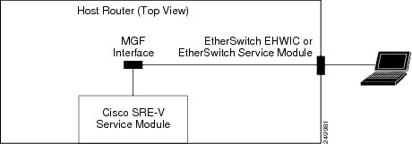
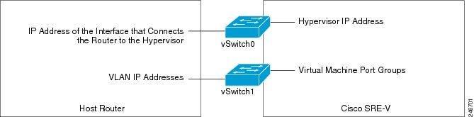
Figure 3-2 shows the location of the IP addresses.
To access the VMware vSphere HypervisorTM through the ISR G2, you must provide two IP addresses: One IP address is of the interface that connects the router to the VMware vSphere HypervisorTM; and the other IP address is of the VMware vSphere HypervisorTM.
The virtual machines are accessed through the MGF interface. The port groups on a vSwitch in the VMware vSphere HypervisorTM can be assigned to corresponding VLAN interfaces in Cisco IOS. For example, port group 50 in the VMware vSphere HypervisorTM can be assigned to VLAN 50 in Cisco IOS.
Figure 3-2 IP Address Location
PREREQUISITES
See the "Prerequisites for Configuring the Cisco SRE Service Module Interfaces" section.
SUMMARY STEPS
From the Host-Router CLI, enter:
1. ![]() enable
enable
2. ![]() configure terminal
configure terminal
Configure slot/0 of the VMware vSphere HypervisorTM
1. ![]() interface sm slot/0
interface sm slot/0
2. ![]() ip address router-to-hypervisor-interface-IP-address subnet-mask
ip address router-to-hypervisor-interface-IP-address subnet-mask
or
[ip unnumbered type number]
3. ![]() service-module ip address hypervisor-ip-address subnet-mask
service-module ip address hypervisor-ip-address subnet-mask
4. ![]() service-module ip default-gateway hypervisor-gateway-ip-address
service-module ip default-gateway hypervisor-gateway-ip-address
5. ![]() no shut
no shut
6. ![]() exit
exit
7. ![]() [ip route hypervisor-ip-address subnet-mask sm slot/0]
[ip route hypervisor-ip-address subnet-mask sm slot/0]
Configure slot/1 of the VMware vSphere HypervisorTM
1. ![]() interface sm slot/1
interface sm slot/1
2. ![]() switchport mode trunk
switchport mode trunk
3. ![]() [switchport trunk allowed vlan vlan_numbers]
[switchport trunk allowed vlan vlan_numbers]
4. ![]() exit
exit
Configure VLANs
1. ![]() configure terminal
configure terminal
2. ![]() interface vlan vlan_number
interface vlan vlan_number
3. ![]() ip address vlan-ip-address subnet mask
ip address vlan-ip-address subnet mask
4. ![]() no shut
no shut
5. ![]() end
end
Save Configuration
1. ![]() copy running-config startup-config
copy running-config startup-config
2. ![]() show running-config
show running-config
DETAILED STEPS
|
|
|
|
|---|---|---|
|
|
||
Step 1 |
enable <password> Router> enable Router> <password> Router# |
Enters privileged EXEC mode on the host router. Enter your password if prompted. |
Step 2 |
configure terminal Router# configure terminal |
Enters global configuration mode on the host router. |
|
|
||
Step 1 |
interface sm slot/0 Router(config)# interface sm 1/0 |
Enters interface configuration mode for the slot and port where the Cisco SRE Service Module resides. |
Step 2 |
ip address router-to-hypervisor-interface-IP-address subnet-mask or [ip unnumbered type number] Router(config-if)# ip address 10.0.0.100 255.255.255.0 or Router(config-if)# ip unnumbered gigabitethernet 1/0 |
Specifies the IP address of the interface that connects the router to the VMware vSphere HypervisorTM. See Figure 3-2. • • or (Optional) The ip unnumbered command enables IP processing on an interface without assigning an explicit IP address to that interface. • • Note 
Caution Note |
Step 3 |
service-module ip address hypervisor-ip-address subnet-mask Router(config-if)# service-module ip address 10.0.0.1 255.255.255.0 |
Specifies the IP address of the VMware vSphere HypervisorTM. • • |
Step 4 |
service-module ip default-gateway hypervisor-gateway-ip-address Router(config-if)# service-module ip default-gateway 10.0.0.100 |
Specifies the IP address of the default gateway for the VMware vSphere HypervisorTM. • |
Step 5 |
no shut Router(config-if)# no shut |
Causes the interface to be administratively up. |
Step 6 |
exit Router(config)# exit |
Returns to global configuration mode on the host router. |
Step 7 |
[ip route hypervisor-ip-address subnet-mask sm slot/0] Router(config)# ip route 10.0.0.1 255.255.255.255 SM1/0 |
Creates a static route. If you used the ip unnumbered command in Step 2, you must use the ip route hypervisor-ip-address subnet-mask sm slot/0 command to create a static route. • • |
|
|
||
Step 1 |
interface sm slot/1 Router(config)# interface sm 1/1 |
Enters interface configuration mode for the slot and port where the Cisco SRE Service Module resides. |
Step 2 |
switchport mode trunk Router(config-if)# switchport mode trunk |
Puts the port into permanent trunking mode. The default configuration is access mode. |
Step 3 |
[switchport trunk allowed vlan vlan_numbers] Router(config-if)# switchport mode trunk Router(config-if)# switchport trunk allowed vlan 1-2,40,60,1002-1005 |
(Optional) Allows trunking on the specified VLANs. • |
Step 4 |
exit Router(config)# exit |
Returns to global configuration mode on the host router. |
|
|
||
Step 1 |
configure terminal Router# configure terminal |
Enters global configuration mode on the host router. |
Step 2 |
interface vlan vlan_number Router(config)# interface vlan 40 |
Enters VLAN configuration mode for the specified VLAN number. |
Step 3 |
ip address vlan-ip-address subnet-mask Router(config-if)# ip address 40.0.0.100 255.255.255.0 |
Specifies the IP address for the VLAN. • • |
Step 4 |
no shut Router(config-if)# no shut |
Causes the interface to be administratively up. |
Step 5 |
end Router(config)# end |
Returns to global configuration mode on the host router. |
|
|
||
Step 1 |
copy running-config startup-config Router# copy running-config startup-config |
Saves the new running configuration of the router as the startup configuration. |
Step 2 |
show running-config Router# show running-config |
Displays the running configuration of the router so that you can verify the address configurations. |
Example
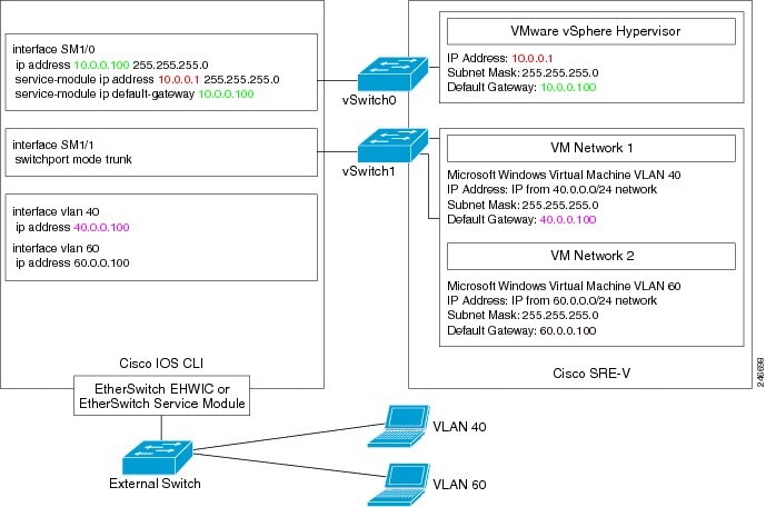
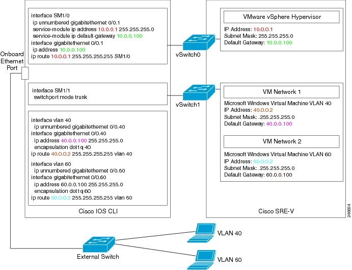
Figure 3-3 shows an example of the MGF Layer 2 switched configuration.
•![]() The left pane shows an example of the Cisco IOS commands that you configure in the
The left pane shows an example of the Cisco IOS commands that you configure in the
sm 1/0, sm 1/1, and VLAN interfaces.
•![]() The right pane shows that the configuration is applied to the VMware vSphere HypervisorTM. The bottom area in the right pane shows the configuration for the Microsoft Windows Servers that are configured using the standard Microsoft Windows network configuration setup process. These Microsoft Windows Serves run as virtual machines.
The right pane shows that the configuration is applied to the VMware vSphere HypervisorTM. The bottom area in the right pane shows the configuration for the Microsoft Windows Servers that are configured using the standard Microsoft Windows network configuration setup process. These Microsoft Windows Serves run as virtual machines.
Note ![]() The IP addresses in the configuration example are for reference only and might not be valid.
The IP addresses in the configuration example are for reference only and might not be valid.
Figure 3-3 Configuration Example of the MGF Layer 2 Switched Configuration
Related Topic
•![]() Downloading the Cisco SRE-V Software, page 4-4
Downloading the Cisco SRE-V Software, page 4-4
Cisco IOS Layer 3 Routed Configuration Options
Figure 3-4 shows the traffic flow in the Cisco IOS Layer 3 routed configuration. The MGF backplane switch forwards the traffic to the router CPU.
Figure 3-4 Traffic Flow in the Cisco IOS Layer 3 Routed Configuration

You can either add the VMware vSphere HypervisorTM and the virtual servers in one branch subnet, and the client PCs in another branch subnet; or you can add all of the devices in the same branch subnet. Depending on which branch subnet you choose to add the devices, the configuration commands that you must use vary. See the following sections for the Cisco IOS Layer 3 routed configuration options:
•![]() Cisco IOS Layer 3 Routed Configuration—Devices in Different Branch Subnets
Cisco IOS Layer 3 Routed Configuration—Devices in Different Branch Subnets
•![]() Cisco IOS Layer 3 Routed Configuration—Devices in the Same Branch Subnet
Cisco IOS Layer 3 Routed Configuration—Devices in the Same Branch Subnet
Cisco IOS Layer 3 Routed Configuration—Devices in Different Branch Subnets
Use this configuration option if you want to add the VMware vSphere HypervisorTM and the virtual servers in one branch subnet; and the client PCs in another branch subnet.
When you assign a subnet to the VMware vSphere HypervisorTM and to the virtual servers, that subnet is automatically added to the routing table as a directly connected route. As long as the client PCs are on a subnet that is reachable from the router, no additional routing configuration is necessary. Typically, the client PCs are on a subnet of the onboard Ethernet interface, which is also automatically added to the routing table as a directly connected route. Therefore, the router sends traffic between the subnet of the VMware vSphere HypervisorTMand the virtual server, and the subnet of the client PCs without any static route or routing protocol configuration.
PREREQUISITES
See the "Prerequisites for Configuring the Cisco SRE Service Module Interfaces" section.
SUMMARY STEPS
From the Host-Router CLI, enter:
1. ![]() enable
enable
2. ![]() configure terminal
configure terminal
Configure slot/0 of the VMware vSphere HypervisorTM
1. ![]() interface sm slot/0
interface sm slot/0
2. ![]() ip address router-to-hypervisor-interface-IP-address subnet-mask
ip address router-to-hypervisor-interface-IP-address subnet-mask
3. ![]() service-module ip address hypervisor-ip-address subnet-mask
service-module ip address hypervisor-ip-address subnet-mask
4. ![]() service-module ip default-gateway hypervisor-gateway-ip-address
service-module ip default-gateway hypervisor-gateway-ip-address
5. ![]() no shut
no shut
6. ![]() exit
exit
Configure slot/1 of the VMware vSphere HypervisorTM
1. ![]() interface sm slot/1
interface sm slot/1
2. ![]() switchport mode trunk
switchport mode trunk
3. ![]() [switchport trunk allowed vlan vlan_numbers]
[switchport trunk allowed vlan vlan_numbers]
4. ![]() exit
exit
Configure VLANs
1. ![]() configure terminal
configure terminal
2. ![]() interface vlan vlan_number
interface vlan vlan_number
3. ![]() ip address vlan-ip-address subnet mask
ip address vlan-ip-address subnet mask
4. ![]() no shut
no shut
5. ![]() exit
exit
Configure Gigabit Ethernet slot/port
1. ![]() interface gigabitethernet slot/port sub-interface
interface gigabitethernet slot/port sub-interface
2. ![]() ip address branch-VLAN-ip-address subnet-mask
ip address branch-VLAN-ip-address subnet-mask
3. ![]() encapsulation dot1q vlan-id
encapsulation dot1q vlan-id
4. ![]() exit
exit
Save Configuration
1. ![]() copy running-config startup-config
copy running-config startup-config
2. ![]() show running-config
show running-config
DETAILED STEPS
|
|
|
|
|---|---|---|
|
|
||
Step 1 |
enable <password> Router> enable Router> <password> Router# |
Enters privileged EXEC mode on the host router. Enter your password if prompted. |
Step 2 |
configure terminal Router# configure terminal |
Enters global configuration mode on the host router. |
|
|
||
Step 1 |
interface sm slot/0 Router(config)# interface sm 1/0 |
Enters interface configuration mode for the slot and port where the Cisco SRE Service Module resides. |
Step 2 |
ip address router-to-hypervisor-interface-IP-address subnet-mask Router(config-if)# ip address 10.0.0.100 255.255.255.0 |
Specifies the IP address of the interface that connects the router to the VMware vSphere HypervisorTM. See Figure 3-2. • • |
Step 3 |
service-module ip address hypervisor-ip-address subnet-mask Router(config-if)# service-module ip address 10.0.0.1 255.255.255.0 |
Specifies the IP address of the VMware vSphere HypervisorTM. • • |
Step 4 |
service-module ip default-gateway hypervisor-gateway-ip-address Router(config-if)# service-module ip default-gateway 10.0.0.100 |
Specifies the IP address of the default gateway for the VMware vSphere HypervisorTM. • |
Step 5 |
no shut Router(config-if)# no shut |
Causes the interface to be administratively up. |
Step 6 |
exit Router(config)# exit |
Returns to global configuration mode on the host router. |
|
|
||
Step 1 |
interface sm slot/1 Router(config)# interface sm 1/1 |
Enters interface configuration mode for the slot and port where the Cisco SRE Service Module resides. |
Step 2 |
switchport mode trunk Router(config-if)# switchport mode trunk |
Puts the port into permanent trunking mode. The default configuration is access mode. Access mode works with native VLAN, which is VLAN 1 for the |
Step 3 |
[switchport trunk allowed vlan vlan_numbers] Router(config-if)# switchport mode trunk Router(config-if)# switchport trunk allowed vlan 1-2,40,60,1002-1005 |
(Optional) Allows trunking on the specified VLANs. • |
Step 4 |
exit Router(config)# exit |
Returns to global configuration mode on the host router. |
|
|
||
Step 1 |
configure terminal Router# configure terminal |
Enters global configuration mode on the host router. |
Step 2 |
interface vlan vlan_number Router(config)# interface vlan 40 |
Enters VLAN configuration mode for the specified VLAN number. |
Step 3 |
ip address vlan-ip-address subnet-mask Router(config-if)# ip address 40.0.0.100 255.255.255.0 |
Specifies the IP address for the VLAN. • • |
Step 4 |
no shut Router(config-if)# no shut |
Causes the interface to be administratively up. |
Step 5 |
exit Router(config)# exit |
Returns to global configuration mode on the host router. |
|
|
||
Step 1 |
interface gigabitethernet slot/port sub-interface Router(config)# interface gigabitethernet 0/1.120 |
Enters Gigabit Ethernet configuration mode for the specified sub interface. • • |
Step 2 |
ip address branch-VLAN-ip-address subnet-mask Router(config-if)# ip address 80.80.120.1 255.255.255.0 |
Configures the IP address for the specific branch VLAN. • |
Step 3 |
encapsulation dot1q vlan-id Router(config-if)# encapsulation dot1q 120 |
Enables IEEE 802.1Q encapsulation of traffic on the specified subinterface in VLANs. • |
Step 4 |
exit |
Exits interface mode. |
|
|
||
Step 1 |
copy running-config startup-config Router# copy running-config startup-config |
Saves the new running configuration of the router as the startup configuration. |
Step 2 |
show running-config Router# show running-config |
Displays the running configuration of the router so that you can verify the address configurations. |
Example
Figure 3-5 shows an example of the Cisco IOS Layer 3 routed configuration in which the VMware vSphere HypervisorTM and the virtual servers are in one branch subnet; and the client PCs are in another branch subnet.
•![]() The left pane shows an example of the Cisco IOS commands that you configure in the
The left pane shows an example of the Cisco IOS commands that you configure in the
sm 1/0, sm 1/1, and VLAN interfaces.
•![]() The right pane shows that the configuration is applied to the VMware vSphere HypervisorTM. The bottom area in the right pane shows the configuration for the Microsoft Windows Servers that are configured using the standard Microsoft Windows network configuration setup process. These Microsoft Windows Serves run as virtual machines.
The right pane shows that the configuration is applied to the VMware vSphere HypervisorTM. The bottom area in the right pane shows the configuration for the Microsoft Windows Servers that are configured using the standard Microsoft Windows network configuration setup process. These Microsoft Windows Serves run as virtual machines.
Note ![]() The IP addresses in the configuration example are for reference only and might not be valid.
The IP addresses in the configuration example are for reference only and might not be valid.
Figure 3-5 Cisco IOS Layer 3 Routed Configuration—Devices in Different Subnets
Related Topics
•![]() Cisco IOS Layer 3 Routed Configuration—Devices in the Same Branch Subnet
Cisco IOS Layer 3 Routed Configuration—Devices in the Same Branch Subnet
•![]() Downloading the Cisco SRE-V Software, page 4-4
Downloading the Cisco SRE-V Software, page 4-4
Cisco IOS Layer 3 Routed Configuration—Devices in the Same Branch Subnet
Use this configuration option if you want to add the VMware vSphere HypervisorTM and the virtual servers in the same branch subnet as the client PCs.
Use the ip unnumbered interface configuration to place the VMware vSphere HypervisorTM and the virtual servers on the same subnet as the client PCs. Because the ip unnumbered interface configuration creates two interfaces with the same subnet in Cisco IOS, you must also configure static routes for the VMware vSphere HypervisorTM and the virtual servers.
PREREQUISITES
See the "Prerequisites for Configuring the Cisco SRE Service Module Interfaces" section.
SUMMARY STEPS
From the Host-Router CLI, enter:
1. ![]() enable
enable
2. ![]() configure terminal
configure terminal
Configure slot/0 of the VMware vSphere HypervisorTM
1. ![]() interface sm slot/0
interface sm slot/0
2. ![]() ip unnumbered gigabitethernet slot/port sub-interface
ip unnumbered gigabitethernet slot/port sub-interface
3. ![]() service-module ip address hypervisor-ip-address subnet-mask
service-module ip address hypervisor-ip-address subnet-mask
4. ![]() service-module ip default-gateway hypervisor-gateway-ip-address
service-module ip default-gateway hypervisor-gateway-ip-address
5. ![]() exit
exit
Configure slot/1 of the VMware vSphere HypervisorTM
1. ![]() interface sm slot/1
interface sm slot/1
2. ![]() switchport mode trunk
switchport mode trunk
3. ![]() [switchport trunk allowed vlan vlan_numbers]
[switchport trunk allowed vlan vlan_numbers]
4. ![]() exit
exit
Configure VLANs
1. ![]() configure terminal
configure terminal
2. ![]() interface vlan vlan_number
interface vlan vlan_number
3. ![]() ip unnumbered gigabitethernet slot/port sub-interface
ip unnumbered gigabitethernet slot/port sub-interface
4. ![]() exit
exit
Configure GE slot/port
1. ![]() interface gigabitethernet slot/port sub-interface
interface gigabitethernet slot/port sub-interface
2. ![]() ip address branch-VLAN-ip-address subnet-mask
ip address branch-VLAN-ip-address subnet-mask
3. ![]() encapsulation dot1q vlan-id
encapsulation dot1q vlan-id
4. ![]() exit
exit
5. ![]() ip route virtual-machine-ip-address subnet-mask vlan vlan_number
ip route virtual-machine-ip-address subnet-mask vlan vlan_number
6. ![]() ip route hypervisor-ip-address subnet-mask sm slot/0
ip route hypervisor-ip-address subnet-mask sm slot/0
7. ![]() exit
exit
Save Configuration
1. ![]() copy running-config startup-config
copy running-config startup-config
2. ![]() show running-config
show running-config
DETAILED STEPS
|
|
|
|
|---|---|---|
|
|
||
Step 1 |
enable <password> Router> enable Router> <password> Router# |
Enters privileged EXEC mode on the host router. Enter your password if prompted. |
Step 2 |
configure terminal Router# configure terminal |
Enters global configuration mode on the host router. |
|
|
||
Step 1 |
interface sm slot/0 Router(config)# interface sm 1/0 |
Enters interface configuration mode for the slot and port where the Cisco SRE Service Module resides. |
Step 2 |
ip unnumbered gigabitethernet slot/port sub-interface Router(config-if)# ip unnumbered gigabitethernet 0/0.1 |
Enables IP processing on an interface without assigning an explicit IP address to that interface. The traffic is forwarded to and from a Gigabit Ethernet sub-interface. • • Note
Caution |
Step 3 |
service-module ip address hypervisor-ip-address subnet-mask Router(config-if)# service-module ip address 10.0.0.1 255.255.255.0 |
Specifies the IP address of the VMware vSphere HypervisorTM. • • |
Step 4 |
service-module ip default-gateway hypervisor-gateway-ip-address Router(config-if)# service-module ip default-gateway 10.0.0.100 |
Specifies the IP address of the default gateway for the VMware vSphere HypervisorTM. • |
Step 5 |
exit |
Exits interface mode. |
|
|
||
Step 1 |
interface sm slot/1 Router(config)# interface sm 1/1 |
Enters interface configuration mode for the slot and port where the Cisco SRE Service Module resides. |
Step 2 |
switchport mode trunk Router(config-if)# switchport mode trunk |
Puts the port into permanent trunking mode. The default configuration is access mode. Access mode works with native VLAN, which is VLAN 1 for the |
Step 3 |
[switchport trunk allowed vlan vlan_numbers] Router(config-if)# switchport mode trunk Router(config-if)# switchport trunk allowed vlan 1-2,40,60,1002-1005 |
(Optional) Allows trunking on the specified VLANs. • |
Step 4 |
exit Router(config)# exit |
Returns to global configuration mode on the host router. |
|
|
||
Step 1 |
configure terminal Router# configure terminal |
Enters global configuration mode on the host router. |
Step 2 |
interface vlan vlan_number Router(config)# interface vlan 40 |
Enters VLAN configuration mode for the specified VLAN number. |
Step 3 |
ip unnumbered gigabitethernet slot/port sub-interface Router(config-if)# ip unnumbered gigabitethernet 0/0.40 |
Enables IP processing on an interface without assigning an explicit IP address to that interface. The traffic is forwarded to and from a Gigabit Ethernet sub-interface. • • Note
Caution |
Step 4 |
exit |
Exits interface mode. |
|
|
||
Step 1 |
interface gigabitethernet slot/port sub-interface Router(config)# interface gigabitethernet 0/0.40 |
Enters Gigabit Ethernet configuration mode for the specified sub interface. • • |
Step 2 |
ip address branch-VLAN-ip-address subnet-mask Router(config-if)# ip address 40.0.0.100 255.255.255.0 |
Configures the IP address for the specific branch VLAN. • |
Step 3 |
encapsulation dot1q vlan-id Router(config-if)# encapsulation dot1q 40 |
Enables IEEE 802.1Q encapsulation of traffic on the specified subinterface in VLANs. • |
Step 4 |
exit |
Exits interface mode. |
Step 5 |
ip route virtual-machine-ip-address subnet-mask vlan vlan_number Router(config)# ip route 40.0.0.2 255.255.255.0 vlan 40 |
Creates a static route entry for the virtual machine. • |
Step 6 |
ip route hypervisor-ip-address subnet-mask sm slot/0 Router(config)# ip route 10.0.0.1 255.255.255.255 SM1/0 |
Creates a static route. • • |
Step 7 |
exit |
Exits interface mode. |
|
|
||
Step 1 |
copy running-config startup-config Router# copy running-config startup-config |
Saves the new running configuration of the router as the startup configuration. |
Step 2 |
show running-config Router# show running-config |
Displays the running configuration of the router so that you can verify the address configurations. |
Example
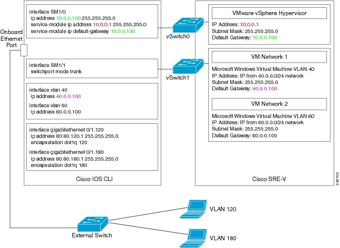
Figure 3-6 shows an example of the Cisco IOS Layer 3 routed configuration where the VMware vSphere HypervisorTM and the virtual servers are in the same branch subnet as the client PCs.
•![]() The left pane shows an example of the Cisco IOS commands that you configure in the
The left pane shows an example of the Cisco IOS commands that you configure in the
sm 1/0, sm 1/1, VLAN, and Gigabit Ethernet interfaces.
•![]() The right pane shows that the configuration is applied to the VMware vSphere HypervisorTM. The bottom area in the right pane shows the configuration for the Microsoft Windows Servers that are configured using the standard Microsoft Windows network configuration setup process. These Microsoft Windows Serves run as virtual machines.
The right pane shows that the configuration is applied to the VMware vSphere HypervisorTM. The bottom area in the right pane shows the configuration for the Microsoft Windows Servers that are configured using the standard Microsoft Windows network configuration setup process. These Microsoft Windows Serves run as virtual machines.
Note ![]() The IP addresses in the configuration example are for reference only and might not be valid.
The IP addresses in the configuration example are for reference only and might not be valid.
Figure 3-6 Cisco IOS Layer 3 Routed Configuration—Devices in the Same Subnet
Related Topic
•![]() Downloading the Cisco SRE-V Software, page 4-4
Downloading the Cisco SRE-V Software, page 4-4
External Interface Configuration
The Cisco IOS commands for this configuration are the same as the commands for the "MGF Layer 2 Switched Configuration—Recommended" section or the "Cisco IOS Layer 3 Routed Configuration Options" section, except for the following:
•![]() The IP address of the virtual machine is on a network that is connected to the external interface.
The IP address of the virtual machine is on a network that is connected to the external interface.
•![]() The virtual machine default gateway points to the external interface.
The virtual machine default gateway points to the external interface.
•![]() The static route entry for the virtual machine, which is configured in the Cisco IOS Layer 3 Routed Configuration, is not required.
The static route entry for the virtual machine, which is configured in the Cisco IOS Layer 3 Routed Configuration, is not required.
Figure 3-7 shows the traffic flow in the external interface configuration. The service module sends the traffic through the external interface.
Figure 3-7 Traffic Flow in the External Interface Configuration
To configure the external interface, complete the following steps:
Step 1 ![]() To configure access to the VMware vSphere HypervisorTM, use the configuration commands provided in one of the following sections:
To configure access to the VMware vSphere HypervisorTM, use the configuration commands provided in one of the following sections:
•![]() "MGF Layer 2 Switched Configuration—Recommended" section
"MGF Layer 2 Switched Configuration—Recommended" section
or
•![]() "Cisco IOS Layer 3 Routed Configuration Options" section
"Cisco IOS Layer 3 Routed Configuration Options" section
Step 2 ![]() Use the vSphere Client GUI to configure access to the virtual machine through the external interface. For instructions, see the vSphere Client online help.
Use the vSphere Client GUI to configure access to the virtual machine through the external interface. For instructions, see the vSphere Client online help.
Example
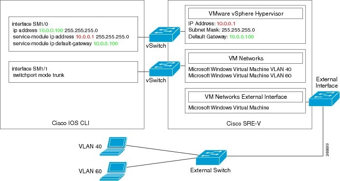
Figure 3-8 shows an example of the external interface configuration.
Note ![]() The IP addresses in the configuration example are for reference only and might not be valid.
The IP addresses in the configuration example are for reference only and might not be valid.
Figure 3-8 External Interface Configuration
Related Topic
•![]() Downloading the Cisco SRE-V Software, page 4-4
Downloading the Cisco SRE-V Software, page 4-4
Reload, Reset, and Shut Down Commands
To reload, reset, or shut down the Cisco SRE Service Module, choose the common router commands listed in Table 3-1. You might choose to shut down the Cisco SRE Service Module for service reasons or to save energy when it is not being used.
Note ![]() For these Cisco IOS service-module commands to take effect, make sure that the Management Network VMkernel port group is configured to use the vSwitch that has the vmnic1 interface as the uplink.
For these Cisco IOS service-module commands to take effect, make sure that the Management Network VMkernel port group is configured to use the vSwitch that has the vmnic1 interface as the uplink.
Note![]() •
•![]() Some shutdown commands can potentially disrupt service. If the command output for such a command displays a confirmation prompt, press Enter to confirm; or type n to cancel, and then press Enter. You can prevent the prompt from being displayed by using the no-confirm keyword.
Some shutdown commands can potentially disrupt service. If the command output for such a command displays a confirmation prompt, press Enter to confirm; or type n to cancel, and then press Enter. You can prevent the prompt from being displayed by using the no-confirm keyword.
•![]() Some commands shut down the module or application, and then immediately restart it.
Some commands shut down the module or application, and then immediately restart it.
|
|
|
|
|---|---|---|
Router# |
service-module sm slot/0 reload |
Gracefully shuts down the Cisco SRE Service Module and then powers it on. |
Router# |
service-module sm slot/0 reset |
Resets the hardware on the Cisco SRE Service Module. Use this command only to recover from a shutdown or failed state.
Caution |
Router# |
service-module sm slot/0 shutdown |
Shuts down the Cisco SRE Service Module system gracefully. Use this command when removing or replacing a hot-swappable module during online insertion and removal (OIR). See the "Online Insertion and Removal of the Cisco SRE Service Module" section on page 2-3. If the virtual machines on the VMware vSphere HypervisorTM have VMware tools installed on them, and you issue this command, the virtual machines shut down first, and then the Cisco SRE Service Module shuts down. If the virtual machines do not have VMware tools installed on them, and you issue this command, the virtual machines get powered off first, and then the shutdown signal is sent to the service module. After about two minutes, the Cisco SRE Service Module shuts down. |
 Feedback