- Overview
- Installing and Upgrading Software
- Configuring Cisco IOS WAN Interfaces
- Configuring Linux Point-to-Point Interfaces
- Configuring Linux Multipoint Interfaces
- Configuring Redirection using WCCP on Data Centers
- Configuring Load Balancing with WCCP on Data Centers
- Configuring Network Address Translation on NCE
- Sample Configurations
- Troubleshooting
- Command Reference
Network Capacity Expansion User Guide
Bias-Free Language
The documentation set for this product strives to use bias-free language. For the purposes of this documentation set, bias-free is defined as language that does not imply discrimination based on age, disability, gender, racial identity, ethnic identity, sexual orientation, socioeconomic status, and intersectionality. Exceptions may be present in the documentation due to language that is hardcoded in the user interfaces of the product software, language used based on RFP documentation, or language that is used by a referenced third-party product. Learn more about how Cisco is using Inclusive Language.
- Updated:
- March 18, 2015
Chapter: Configuring Network Address Translation on NCE
Configuring NAT for NCE
Contents
•![]() Configuring Network Address Translation (NAT) with NCE
Configuring Network Address Translation (NAT) with NCE
•![]() Configuring NAT for NCE with Public IP Addresses
Configuring NAT for NCE with Public IP Addresses
Configuring Network Address Translation (NAT) with NCE
The goal of NAT is to provide functionality as if the private network had globally unique addresses and the NAT device was not present. RFC 1631 represents a subset of Cisco IOS NAT functionality. Several internal addresses can be translated to only one or a few external addresses by using a feature called Port Address Translation (PAT), also referred to as overload, a subset of NAT functionality.
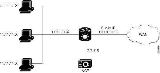
The following sample configuration uses these IP addresses:
•![]() Public IP: 10.x.x.x
Public IP: 10.x.x.x
•![]() Transport-local IP address 7.x.x.x
Transport-local IP address 7.x.x.x
•![]() Lan (local Client IP): 11.x.x.x
Lan (local Client IP): 11.x.x.x
Figure 8-1 Topology for NAT with NCE
Configure the Cisco IOS

Note ![]() The NCE module is configured in the private domain.
The NCE module is configured in the private domain.
Configure NAT on the Cisco IOS side as follows:
Step 1 ![]() Configure the transport-opt interface and Cisco IOS WAN as the NAT outside interface; configure the LAN interface as the inside interface.
Configure the transport-opt interface and Cisco IOS WAN as the NAT outside interface; configure the LAN interface as the inside interface.
interface Serial0/2/0
ip address 10.10.10.11 255.255.0.0 (public side ip address)
ip nat outside
ip virtual-reassembly
load-interval 30
clock rate 8000000
transport-opt 3 interface Transport-Opt-Service-Engine4/0
!
interface Transport-Opt-Service-Engine4/0 (configured as an outside interface)
ip address 7.7.7.7 255.255.0.0
ip nat outside
ip virtual-reassembly
load-interval 30
service-module ip address 7.7.7.8 255.255.0.0
service-module ip default-gateway 7.7.7.7
hold-queue 60 out
interface GigabitEthernet0/0 ( Inside LAN interface)
no ip address
ip virtual-reassembly
load-interval 30
duplex auto
speed auto
media-type rj45
!
interface GigabitEthernet0/0.1
encapsulation dot1Q 2
ip address 11.11.11.11 255.255.0.0
ip nat inside
ip virtual-reassembly
Step 2 ![]() Configures a static NAT entry mapping the transport-opt service module IP address to the public IP address.
Configures a static NAT entry mapping the transport-opt service module IP address to the public IP address.
ip nat pool test 10.10.10.11 10.10.10.11 prefix-length 24
ip nat inside source list 100 pool test overload
ip nat inside source static 7.7.7.8 10.10.10.11
Step 3 ![]() Capture all the TCP traffic using an access-list on the input LAN interface and change the src-ip to the public IP address.
Capture all the TCP traffic using an access-list on the input LAN interface and change the src-ip to the public IP address.
access-list 100 permit ip 11.11.11.0 0.0.0.255 any
Step 4 ![]() Allow ICMP traffic in the access-list configured for NAT.
Allow ICMP traffic in the access-list configured for NAT.
access-list 100 permit icmp any any
Configure NCE
Configure NAT on the NCE service module as follows:
Step 1 ![]() Configure NAT inside src as the global address for all the networks that needs to be reached from the service module.
Configure NAT inside src as the global address for all the networks that needs to be reached from the service module.
This example shows the server network and other side TPO network.
tpo id 3
bandwidth 7900 7500
default policy-action compress-sctp
sctp-peer 14.14.14.15
exit
tpo ip nat inside source 10.10.10.11 14.14.14.0 255.255.255.0
Step 2 ![]() After configuring the client side, login into the server side module. The remote end SCTP peer IP now needs to be mapped to the NAT Global IP address on the client end.
After configuring the client side, login into the server side module. The remote end SCTP peer IP now needs to be mapped to the NAT Global IP address on the client end.
The remote side configuration should look like this:
tpo id 3
bandwidth 7900 7500
default policy-action optimize
sctp-peer 10.10.10.11
In the following output, protocol 132 are SCTP packets. Others are TCP packets captured at the LAN side and the address is changed to a global address.
CA-3845-1#sh ip nat translations
Pro Inside global Inside local Outside local Outside global
132 10.10.10.11:0 7.7.7.8:0 1.3.202.97:0 1.3.202.97:0
132 10.10.10.11:0 7.7.7.8:0 14.14.14.15:0 14.14.14.15:0
--- 10.10.10.11 7.7.7.8 --- ---
tcp 10.10.10.11:35286 11.11.11.12:35286 9.9.9.10:143 9.9.9.10:143
tcp 10.10.10.11:35797 11.11.11.12:35797 9.9.9.10:143 9.9.9.10:143
tcp 10.10.10.11:35808 11.11.11.12:35808 9.9.9.10:110 9.9.9.10:110
tcp 10.10.10.11:35846 11.11.11.12:35846 9.9.9.10:110 9.9.9.10:110
tcp 10.10.10.11:35866 11.11.11.12:35866 9.9.9.10:110 9.9.9.10:110
tcp 10.10.10.11:35936 11.11.11.12:35936 9.9.9.10:110 9.9.9.10:110
tcp 10.10.10.11:35984 11.11.11.12:35984 9.9.9.10:110 9.9.9.10:110
tcp 10.10.10.11:35985 11.11.11.12:35985 9.9.9.10:110 9.9.9.10:110
tcp 10.10.10.11:36014 11.11.11.12:36014 9.9.9.10:110 9.9.9.10:110
tcp 10.10.10.11:36027 11.11.11.12:36027 9.9.9.10:110 9.9.9.10:110
tcp 10.10.10.11:36049 11.11.11.12:36049 9.9.9.10:110 9.9.9.10:110
tcp 10.10.10.11:36050 11.11.11.12:36050 9.9.9.10:110 9.9.9.10:110
Configuring NAT for NCE with Public IP Addresses
This section describes how to configure NAT with NCE when NCE is also configured with public IP addresses.
Note ![]() When the NCE module is configured with public address, no NAT-specific configuration is required on the service module.
When the NCE module is configured with public address, no NAT-specific configuration is required on the service module.
crypto isakmp policy 5
authentication pre-share
crypto isakmp key 6 cisco address 10.10.10.10 no-xauth
!
!
!
crypto map TPO-TEST 5 ipsec-isakmp
set peer 10.10.10.10
match address 100
!
interface GigabitEthernet0/0
ip address 11.11.11.11 255.255.0.0
ip nat inside
duplex auto
speed auto
interface GigabitEthernet0/1/0
ip address 10.10.10.11 255.255.0.0
ip nat outside
ip virtual-reassembly
load-interval 30
negotiation auto
transport-opt 10 interface Transport-Opt-Service-Engine4/0
crypto map TPO-TEST
interface Transport-Opt-Service-Engine4/0
ip address 10.10.10.12 255.255.0.0
ip nat outside
ip virtual-reassembly
load-interval 30
service-module ip address 10.10.10.13 255.255.0.0
service-module ip default-gateway 10.10.10.12
hold-queue 60 out
ip route 0.0.0.0 0.0.0.0 10.10.10.10
ip route 10.10.10.13 255.255.255.255 Transport-Opt-Service-Engine4/0
ip nat pool test 10.10.10.11 10.10.10.11 prefix-length 24
ip nat inside source list 100 pool test overload
!
access-list 100 permit ip 10.10.0.0 0.0.255.255 any
access-list 100 permit 132 any any
access-list 100 permit icmp any any
access-list 100 permit tcp any any
!
 Feedback