PA-4E1G Serial Port Adapter Installation and Configuration
Bias-Free Language
The documentation set for this product strives to use bias-free language. For the purposes of this documentation set, bias-free is defined as language that does not imply discrimination based on age, disability, gender, racial identity, ethnic identity, sexual orientation, socioeconomic status, and intersectionality. Exceptions may be present in the documentation due to language that is hardcoded in the user interfaces of the product software, language used based on RFP documentation, or language that is used by a referenced third-party product. Learn more about how Cisco is using Inclusive Language.
- Updated:
- September 14, 2007
Chapter: Configuring the PA-4E1G
Configuring the PA-4E1G
To continue your PA-4E1G installation, you must configure the serial interfaces. The instructions that follow apply to all supported platforms. Minor differences between the platforms—with Cisco IOS software commands—are noted.
This chapter contains the following sections:
•![]() Using the EXEC Command Interpreter
Using the EXEC Command Interpreter
•![]() Customizing the Configuration
Customizing the Configuration
Using the EXEC Command Interpreter
You modify the configuration of your router through the software command interpreter called the EXEC (also called enable mode). You must enter the privileged level of the EXEC command interpreter with the enable command before you can use the configure command to configure a new interface or to change the existing configuration of an interface. The system prompts you for a password if one has been set.
The system prompt for the privileged level ends with a pound sign (#) instead of an angle bracket (>). At the console terminal, use the following procedure to enter the privileged level:
Step 1 ![]() At the user-level EXEC prompt, enter the enable command. The EXEC prompts you for a privileged-level password as follows:
At the user-level EXEC prompt, enter the enable command. The EXEC prompts you for a privileged-level password as follows:
Router> enable
Password:
Step 2 ![]() Enter the password (the password is case sensitive). For security purposes, the password is not displayed.
Enter the password (the password is case sensitive). For security purposes, the password is not displayed.
When you enter the correct password, the system displays the privileged-level system prompt (#):
Router#
To configure the new interfaces, proceed to the "Configuring the Interfaces" section.
Configuring the Interfaces
After you verify that the new PA-4E1G is installed correctly (the enabled LED goes on), use the privileged-level configure command to configure the new interfaces. Have the following information available:
•![]() Protocols you plan to route on each new interface
Protocols you plan to route on each new interface
•![]() IP addresses, if you plan to configure the interfaces for IP routing
IP addresses, if you plan to configure the interfaces for IP routing
•![]() Bridging protocols you plan to use
Bridging protocols you plan to use
•![]() Clock timing source you plan to use for each new interface and clock speeds for external timing
Clock timing source you plan to use for each new interface and clock speeds for external timing
If you installed a new PA-4E1G or if you want to change the configuration of an existing interface, you must enter configuration mode to configure the new interfaces. If you replaced a PA-4E1G that was previously configured, the system recognizes the new interfaces and brings them up in their existing configurations.
For a summary of the configuration options available and instructions for configuring interfaces on a PA-4E1G, refer to the appropriate configuration publications listed in the "Related Documentation" section.
You execute configuration commands from the privileged level of the EXEC command interpreter, which usually requires password access. Contact your system administrator, if necessary, to obtain password access. (See the "Using the EXEC Command Interpreter" section for an explanation of the privileged level of the EXEC.)
This section contains the following subsections:
•![]() Performing a Basic Interface Configuration
Performing a Basic Interface Configuration
Shutting Down an Interface
Before you remove an interface that you will not replace, or replace port adapters, use the shutdown command to shut down (disable) the interfaces to prevent anomalies when you reinstall the new or reconfigured port adapter. When you shut down an interface, it is designated administratively down in the show command displays.
Follow these steps to shut down an interface:
Step 1 ![]() Enter the privileged level of the EXEC command interpreter (also called enable mode). (See the "Using the EXEC Command Interpreter" section for instructions.)
Enter the privileged level of the EXEC command interpreter (also called enable mode). (See the "Using the EXEC Command Interpreter" section for instructions.)
Step 2 ![]() At the privileged-level prompt, enter configuration mode and specify that the console terminal is the source of the configuration subcommands, as follows:
At the privileged-level prompt, enter configuration mode and specify that the console terminal is the source of the configuration subcommands, as follows:
Router# configure terminal
Enter configuration commands, one per line. End with CNTL/Z.
Router(config)#
Step 3 ![]() Shut down interfaces by entering the interface serial subcommand (followed by the interface address of the interface), and then enter the shutdown command.
Shut down interfaces by entering the interface serial subcommand (followed by the interface address of the interface), and then enter the shutdown command.
When you have finished, press Ctrl-Z—hold down the Control key while you press Z—or enter end or exit to exit configuration mode and return to the EXEC command interpreter.
Table 4-1 shows the shutdown command syntax for the supported platforms.

Note ![]() If you need to shut down additional interfaces, enter the interface serial command (followed by the interface address of the interface) for each of the interfaces on your port adapter. Use the no shutdown command to enable the interface.
If you need to shut down additional interfaces, enter the interface serial command (followed by the interface address of the interface) for each of the interfaces on your port adapter. Use the no shutdown command to enable the interface.
Step 4 ![]() Write the new configuration to NVRAM as follows:
Write the new configuration to NVRAM as follows:
Router# copy running-config startup-config
[OK]
Router#
The system displays an OK message when the configuration has been stored in NVRAM.
Step 5 ![]() Verify that new interfaces are now in the correct state (shut down) using the show interfaces command (followed by the interface type and interface address of the interface) to display the specific interface.
Verify that new interfaces are now in the correct state (shut down) using the show interfaces command (followed by the interface type and interface address of the interface) to display the specific interface.
Table 4-2 provides examples of the show interfaces serial command for the supported platforms.
Step 6 ![]() Re-enable interfaces by doing the following:
Re-enable interfaces by doing the following:
a. ![]() Repeat Step 3 to re-enable an interface. Substitute the no shutdown command for the shutdown command.
Repeat Step 3 to re-enable an interface. Substitute the no shutdown command for the shutdown command.
b. ![]() Repeat Step 4 to write the new configuration to memory. Use the copy running-config startup-config command.
Repeat Step 4 to write the new configuration to memory. Use the copy running-config startup-config command.
c. ![]() Repeat Step 5 to verify that the interfaces are in the correct state. Use the show interfaces command followed by the interface type and interface address of the interface.
Repeat Step 5 to verify that the interfaces are in the correct state. Use the show interfaces command followed by the interface type and interface address of the interface.
For complete descriptions of software configuration commands, refer to the publications listed in the "Related Documentation" section.
Performing a Basic Interface Configuration
Following are instructions for a basic configuration, which include enabling an interface and specifying IP routing. You might also need to enter other configuration subcommands, depending on the requirements for your system configuration and the protocols you plan to route on the interface. For complete descriptions of configuration subcommands and the configuration options available for serial interfaces, refer to the appropriate software documentation.
In the following procedure, press the Return key after each step unless otherwise noted. At any time you can exit the privileged level and return to the user level by entering disable at the prompt as follows:
Router# disable
Router>
Step 1 ![]() Enter configuration mode and specify that the console terminal is the source of the configuration subcommands as follows:
Enter configuration mode and specify that the console terminal is the source of the configuration subcommands as follows:
Router# configure terminal
Enter configuration commands, one per line. End with CNTL/Z.
Router(config)#
Step 2 ![]() Specify the first interface to configure by entering the subcommand interface serial subcommand, followed by the interface address of the interface you plan to configure.
Specify the first interface to configure by entering the subcommand interface serial subcommand, followed by the interface address of the interface you plan to configure.
Table 4-3 gives examples of the interface serial subcommand for the supported platforms.
Step 3 ![]() Assign an IP address and subnet mask to the interface (if IP routing is enabled on the system) by using the ip address subcommand, as in the following example:
Assign an IP address and subnet mask to the interface (if IP routing is enabled on the system) by using the ip address subcommand, as in the following example:
Router(config-if)# ip address 10.0.0.0 10.255.255.255
Step 4 ![]() Add any additional configuration subcommands required to enable routing protocols and set the interface characteristics.
Add any additional configuration subcommands required to enable routing protocols and set the interface characteristics.
Step 5 ![]() Re-enable the interfaces using the no shutdown command. (See the "Shutting Down an Interface" section.)
Re-enable the interfaces using the no shutdown command. (See the "Shutting Down an Interface" section.)
Step 6 ![]() Configure all additional port adapter interfaces as required.
Configure all additional port adapter interfaces as required.
Step 7 ![]() After including all of the configuration subcommands to complete your configuration, press Ctrl-Z—hold down the Control key while you press Z—or enter end or exit to exit configuration mode and return to the EXEC command interpreter prompt.
After including all of the configuration subcommands to complete your configuration, press Ctrl-Z—hold down the Control key while you press Z—or enter end or exit to exit configuration mode and return to the EXEC command interpreter prompt.
Step 8 ![]() Write the new configuration to NVRAM as follows:
Write the new configuration to NVRAM as follows:
Router# copy running-config startup-config
[OK]
Router#
This completes the procedure for creating a basic configuration.
Customizing the Configuration
Use the privileged-level configure command to perform an advanced interface configuration. You will need the following information to perform this configuration:
•![]() Timing source for each new interface (a line-derived or internal clock signal)
Timing source for each new interface (a line-derived or internal clock signal)
•![]() Whether you will use framed or unframed mode on the interfaces
Whether you will use framed or unframed mode on the interfaces
•![]() The cyclic redundancy check (CRC) you want to use
The cyclic redundancy check (CRC) you want to use

This section contains the following topics:
•![]() Configuring Framed and Unframed Mode
Configuring Framed and Unframed Mode
•![]() Configuring Timing (Clock) Signals
Configuring Timing (Clock) Signals
•![]() Configuring Cyclic Redundancy Checks
Configuring Cyclic Redundancy Checks
Configuring Framed and Unframed Mode
The PA-4E1G supports both framed (G.704) and unframed (G.703) modes of operation; the default is unframed operation.
To enable framed operation, you must specify the start and stop slots, separated by a hyphen, as follows:
timeslot 0/start-slot-31/stop-slot
Following is an example of using the timeslot command with a start slot of 1 and a stop slot of 13:
Router# timeslot 1-13
Nonconfigurable combinations of start and stop slots will be ignored, and the interface will be left unchanged.
In framed mode, the system default is not to use time slot 16 for data. To use slot 16 for data, use the ts16 command in addition to the timeslot 1-17 command, as follows:
Router# timeslot 1-17
Router# ts16
To restore the system default, use the no ts16 command.
Configuring Timing (Clock) Signals
Each PA-4E1G operates either with an external clock signal that it recovers from the received data stream or its own internal clock signal. The default is the external clock source line.
To specify the clock source, use the clock source {line | internal} command.
To change the default and use the internal clock, use the clock source internal command.
To return the interface to the default state, use the clock source line command. (The no clock source internal command also returns the interface to the default state.)
Note ![]() All E1-G.703/G.704 interfaces operate at a default clock rate of 2.048 Mbps; you cannot configure the clock rate.
All E1-G.703/G.704 interfaces operate at a default clock rate of 2.048 Mbps; you cannot configure the clock rate.
Configuring Cyclic Redundancy Checks
The 4-bit cyclic redundancy check (CRC4) is an error-checking technique that uses a calculated numeric value to detect errors in transmitted data. By default, CRC4 is not enabled. The sender of a data frame calculates the frame check sequence (FCS). Before it sends a frame, the sender appends the FCS value to the message. The receiver recalculates the FCS and compares its calculation to the FCS from the sender. If there is a difference between the two calculations, the receiver assumes that a transmission error occurred and sends a request to the sender to resend the frame.
Note ![]() The E1-G.703/G.704 interface on the PA-4E1G is compliant with BABT 221. The E1-G.703/G.704 interface supports CRC4 in framed mode only.
The E1-G.703/G.704 interface on the PA-4E1G is compliant with BABT 221. The E1-G.703/G.704 interface supports CRC4 in framed mode only.
Table 4-4 summarizes cyclic redundancy check (CRC) commands.
Enable CRC4 using the crc 4 command. Before you can enable 4-bit CRC, you must use the interface serial command (followed by the interface address of the interface) to select the interface on which you want to enable 4-bit CRC. This command functions in the same way on all supported platforms.
In the example that follows, 4-bit CRC is specified:
Router(config-if)# crc 4
The preceding command example applies to all systems in which the PA-4E1G is supported. Use the no crc 4 command to disable CRC4 and return the interface to the default CRC disabled setting.
When you have finished, press Ctrl-Z—hold down the Control key while you press Z—or enter end or exit to exit configuration mode and return to the EXEC command interpreter prompt. Then write the new configuration to NVRAM using the copy running-config startup-config command.
For command descriptions, refer to the Configuration Fundamentals Configuration Guide.
Checking the Configuration
After configuring the new interface, use the show commands to display the status of the new interface or all interfaces, and use the ping and loopback commands to check connectivity. This section includes the following subsections:
•![]() Using show Commands to Verify the New Interface Status
Using show Commands to Verify the New Interface Status
•![]() Using the ping Command to Verify Network Connectivity
Using the ping Command to Verify Network Connectivity
Using show Commands to Verify the New Interface Status
Table 4-5 demonstrates how you can use the show commands to verify that new interfaces are configured and operating correctly and that the PA-4E1G appears in them correctly. Sample displays of the output of selected show commands appear in the sections that follow. For complete command descriptions and examples, refer to the publication listed in the "Related Documentation" section.
Note ![]() The outputs that appear in this document may not match the output you receive when running these commands. The outputs in this document are examples only.
The outputs that appear in this document may not match the output you receive when running these commands. The outputs in this document are examples only.
If the interface is down and you configured it as up, or if the displays indicate that the hardware is not functioning properly, ensure that the interface is properly connected and terminated. If you still have problems bringing up the interface, contact a service representative for assistance. This section includes the following subsections:
•![]() Using the show version or show hardware Commands
Using the show version or show hardware Commands
•![]() Using the show interfaces Command
Using the show interfaces Command
Using the show version or show hardware Commands
Display the configuration of the system hardware, the number and type of each interface type installed, the Cisco IOS software version, the names and sources of configuration files, and the boot images, using the show version (or show hardware) command.
Note ![]() The outputs that appear in this document may not match the output you receive when running these commands. The outputs in this document are examples only.
The outputs that appear in this document may not match the output you receive when running these commands. The outputs in this document are examples only.
The following sections offer some platform-specific output examples using the show version command:
•![]() Cisco 7100 Series Routers—Example Output of the show version Command
Cisco 7100 Series Routers—Example Output of the show version Command
•![]() Cisco 7201 Router—Example Output of the show version Command
Cisco 7201 Router—Example Output of the show version Command
•![]() Cisco 7401ASR Router—Example Output of the show version Command
Cisco 7401ASR Router—Example Output of the show version Command
•![]() VIP in Cisco 7000 Series and Cisco 7500 Series Routers—Example Output of the show version Command
VIP in Cisco 7000 Series and Cisco 7500 Series Routers—Example Output of the show version Command
Cisco 7100 Series Routers—Example Output of the show version Command
Following is an example of the show version command from a Cisco 7120 series router with a PA-4E1G installed:
Router# show version
Cisco Internetwork Operating System Software
IOS (tm) EGR Software (c7100-IS-M), Version 12.0(4)XE, EARLY DEPLOYMENT
RELEASE)
TAC:Home:SW:IOS:Specials for info
Copyright (c) 1986-1999 by cisco Systems, Inc.
Compiled Thu 10-Jun-99 15:32 by linda
Image text-base:0x60008900, data-base:0x60D8E000
ROM:System Bootstrap, Version 12.0(19990720:023243)
[gautham-conn_4xe-PRE_ALPHE
BOOTFLASH:EGR Software (c7100-IS-M), Version 12.0(4)XE, EARLY DEPLOYMENT
RELEA)
Router uptime is 24 minutes
System restarted by power-on
System image file is "disk0:c7100-is-mz.120-4.XE"
cisco 7120-bad (EGR) processor with 61440K/69632K bytes of memory.
R527x CPU at 225Mhz, Implementation 40, Rev 10.0, 2048KB L2 Cache
Last reset from power-on
Bridging software.
G.703/E1 software, Version 1.0.
G.703/JT2 software, Version 1.0.
125K bytes of non-volatile configuration memory.
40960K bytes of ATA PCMCIA card at slot 0 (Sector size 512 bytes).
8192K bytes of Flash internal SIMM (Sector size 256K).
Configuration register is 0x2000
Cisco 7200 Series Routers, Cisco 7200 VXR Routers, and Cisco uBR7200 Series Routers—Example Output of the show version Command
Following is an example of the show version command from a Cisco 7200 series router with a PA-4E1G installed:
Router# show version
Cisco Internetwork Operating System Software
IOS (c) 7200 Software (C7200-J-M), Version 11.1(7)CA [biff 105]
Copyright (c) 1986-1996 by cisco Systems, Inc.
Compiled Sun 04-Aug-96 06:00 by biff
Image text-base: 0x600088A0, data-base: 0x605A4000
ROM: System Bootstrap, Version 11.1(7)CA RELEASED SOFTWARE
Router uptime is 4 hours, 22 minutes
System restarted by reload
System image file is "c7200-j-mz", booted via slot0
cisco 7206 (NPE150) processor with 12288K/4096K bytes of memory.
R4700 processor, Implementation 33, Revision 1.0 (Level 2 Cache)
Last reset from power-on
Last reset from power-on
G.703/E1 software, Version 1.0.
G.703/JT2 software, Version 1.0.
SuperLAT software copyright 1990 by Meridian Technology Corp).
Bridging software.
X.25 software, Version 2.0, NET2, BFE and GOSIP compliant.
TN3270 Emulation software (copyright 1994 by TGV Inc).
Chassis Interface.
4 Serial network interfaces.
125K bytes of non-volatile configuration memory.
1024K bytes of packet SRAM memory.
20480K bytes of Flash PCMCIA card at slot 0 (Sector size 128K).
8192K bytes of Flash internal SIMM (Sector size 256K).
Configuration register is 0x2
Cisco 7201 Router—Example Output of the show version Command
Following is an example of the show version command from a Cisco 7201 router:
Router# show version
Cisco IOS Software, 7200 Software (C7200P-ADVENTERPRISEK9-M), Version 12.4(biffDEV.061001), INTERIM SOFTWARE Copyright (c) 1986-2006 by Cisco Systems, Inc.
Compiled Sun 01-Oct-06 23:42 by biff
ROM: System Bootstrap, Version 12.4(4r)XD5, RELEASE SOFTWARE (fc1)
BOOTLDR: Cisco IOS Software, 7200 Software (C7200P-KBOOT-M), Version 12.4(TAZ3DEV.060927), INTERIM SOFTWARE
c7201alpha1 uptime is 5 days, 18 hours, 32 minutes System returned to ROM by power-on System image file is "disk0:c7200p-adventerprisek9-mz.2006-10-01.biffdev"
This product contains cryptographic features and is subject to United States and local country laws governing import, export, transfer and use. Delivery of Cisco cryptographic products does not imply third-party authority to import, export, distribute or use encryption.
Importers, exporters, distributors and users are responsible for compliance with U.S. and local country laws. By using this product you agree to comply with applicable laws and regulations. If you are unable to comply with U.S. and local laws, return this product immediately.
A summary of U.S. laws governing Cisco cryptographic products may be found at:
http://www.cisco.com/wwl/export/crypto/tool/stqrg.html
If you require further assistance please contact us by sending email to export@cisco.com.
Cisco 7201 (c7201) processor (revision A) with 917504K/65536K bytes of memory.
Processor board ID 2222222222222
MPC7448 CPU at 1666Mhz, Implementation 0, Rev 2.2
1 slot midplane, Version 2.255
Last reset from power-on
1 FastEthernet interface
4 Gigabit Ethernet interfaces
2045K bytes of NVRAM.
62443K bytes of USB Flash usbflash0 (Read/Write)
250880K bytes of ATA PCMCIA card at slot 0 (Sector size 512 bytes).
65536K bytes of Flash internal SIMM (Sector size 512K).
Configuration register is 0x2
Cisco 7401ASR Router—Example Output of the show version Command
Following is an example of the show version command from a Cisco 7401ASR router with a PA-4E1G installed:
Router# show version
Cisco Internetwork Operating System Software
IOS (tm) 7401ASR Software (C7401ASR-J-M), Version 11.1(7)CA [biff 105]
Copyright (c) 1986-1996 by cisco Systems, Inc.
Compiled Sun 04-Aug-96 06:00 by biff
Image text-base: 0x600088A0, data-base: 0x605A4000
ROM: System Bootstrap, Version 11.1(7)CA RELEASED SOFTWARE
Router uptime is 4 hours, 22 minutes
System restarted by reload
System image file is "c7401ASR-j-mz", booted via slot0
cisco 7401ASR processor with 12288K/4096K bytes of memory.
R4700 processor, Implementation 33, Revision 1.0 (Level 2 Cache)
Last reset from power-on
Last reset from power-on
G.703/E1 software, Version 1.0.
G.703/JT2 software, Version 1.0.
SuperLAT software copyright 1990 by Meridian Technology Corp).
Bridging software.
X.25 software, Version 2.0, NET2, BFE and GOSIP compliant.
TN3270 Emulation software (copyright 1994 by TGV Inc).
Chassis Interface.
4 Serial network interfaces.
125K bytes of non-volatile configuration memory.
1024K bytes of packet SRAM memory.
20480K bytes of Flash PCMCIA card at slot 0 (Sector size 128K).
8192K bytes of Flash internal SIMM (Sector size 256K).
Configuration register is 0x2
VIP in Cisco 7000 Series and Cisco 7500 Series Routers—Example Output of the show version Command
Following is an example of the show version command from a Cisco 7500 series routers with a PA-4E1G installed:
Router# show version
Cisco Internetwork Operating System Software
IOS (tm) GS Software (RSP-JV-M), Version 11.1(14)CA [biff 184]
Synced to mainline version: 11.1(13)
Copyright (c) 1986-1998 by cisco Systems, Inc.
Compiled Wed 08-Oct-98 00:37 by biff
Image text-base: 0x600108A0, data-base: 0x609DC000
ROM: System Bootstrap, Version 5.3(16645) [biff 571]
ROM: GS Software (RSP-BOOT-M), Version 11.1(618) [biff 191]
Router uptime is 3 hours, 14 minutes
System restarted by reload
System image file is "biff/rsp-jv-mz.g703", booted via tftp from 1.1.1.253
cisco RSP2 (R4600) processor with 32768K bytes of memory.
R4600 processor, Implementation 32, Revision 2.0
Last reset from power-on
G.703/E1 software, Version 1.0.
G.703/JT2 software, Version 1.0.
SuperLAT software copyright 1990 by Meridian Technology Corp).
Bridging software.
X.25 software, Version 2.0, NET2, BFE and GOSIP compliant.
TN3270 Emulation software (copyright 1994 by TGV Inc).
Chassis Interface.
1 VIP2 controllers (4 Serial).
4 Serial network interfaces.
125K bytes of non-volatile configuration memory.
16384K bytes of Flash PCMCIA card at slot 0 (Sector size 128K).
8192K bytes of Flash internal SIMM (Sector size 256K).
No slave installed in slot 7.
Configuration register is 0x2
Using the show diag Command
Display the types of port adapters installed in your system (and specific information about each) using the show diag slot command, where slot is the port adapter slot in a Cisco 7100 series router, Cisco 7200 series router, Cisco 7200 VXR router, Cisco uBR7200 series router, Cisco 7201 router, Cisco 7301 router, and Cisco 7401ASR router, the module slot in a Cisco 7304 PCI Port Adapter Carrier Card in a Cisco 7304 router, and the interface processor slot in a Cisco 7000 series router or Cisco 7500 series router with a VIP.
Note ![]() The outputs that appear in this document may not match the output you receive when running these commands. The outputs in this document are examples only.
The outputs that appear in this document may not match the output you receive when running these commands. The outputs in this document are examples only.
The following sections offer some platform-specific output examples using the show diag command:
•![]() Cisco 7100 Series Routers—Example Output of the show diag Command
Cisco 7100 Series Routers—Example Output of the show diag Command
•![]() Cisco 7201 Router—Example Output of the show diag Command
Cisco 7201 Router—Example Output of the show diag Command
•![]() Cisco 7401ASR Router—Example Output of the show diag Command
Cisco 7401ASR Router—Example Output of the show diag Command
Cisco 7100 Series Routers—Example Output of the show diag Command
Following is an example of the show diag command that shows a PA-4E1G installed in port adapter slot 3 of a Cisco 7120 series router:
Router# show diag 3
Slot 3:
Mx serial (ME1-UNBAL) port adapter, 4 ports
Integrated port adapter is analyzed
EEPROM contents at hardware discovery:
Hardware revision 255.255 Board revision UNKNOWN
EEPROM format version 1
EEPROM contents (hex):
0x20:01 D3 FF FF FF FF FF FF FF FF FF FF FF FF FF FF
0x30:FF FF FF FF FF FF FF FF FF FF FF FF FF FF FF FF
Note ![]() To use the show diag command with the Cisco 7140 series router, replace the slot argument 3 with 4.
To use the show diag command with the Cisco 7140 series router, replace the slot argument 3 with 4.
Cisco 7200 Series Routers, Cisco 7200 VXR Routers, and Cisco uBR7200 Series Routers—Example Output of the show diag Command
Following is an example of the show diag command that shows a PA-4E1G installed in port adapter slot 6 of a Cisco 7200 series router:
Router# show diag 6
Slot 6:
Mx serial (ME1-UNBAL) port adapter, 4 ports
Port adapter is analyzed
Port adapter insertion time 00:48:28 ago
Hardware revision 255.255 Board revision UNKNOWN
Serial number 4294967295 Part number 255-65535-255
Test history 0xFF RMA number 255-255-255
EEPROM format version 255
EEPROM contents (hex):
0x20: FF 41 FF FF FF FF FF FF FF FF FF FF FF FF FF FF
0x30: FF FF FF FF FF FF FF FF FF FF FF FF FF FF FF FF
Cisco 7201 Router—Example Output of the show diag Command
Following is an example of the show diag command from a Cisco 7201 router:
Router# show diag 1
Slot 1:
Dual OC3 POS Port adapter, 2 ports
Port adapter is analyzed
Port adapter insertion time 00:02:19 ago
EEPROM contents at hardware discovery:
Hardware Revision : 1.0
PCB Serial Number : JAE07520DYL
Part Number : 73-8220-02
Board Revision : A0
RMA Test History : 00
RMA Number : 0-0-0-0
RMA History : 00
Deviation Number : 0
Product (FRU) Number : PA-POS-2OC3
Top Assy. Part Number : 800-21857-02
EEPROM format version 4
EEPROM contents (hex):
0x00: 04 FF 40 03 E3 41 01 00 C1 8B 4A 41 45 30 37 35
0x10: 32 30 44 59 4C 82 49 20 1C 02 42 41 30 03 00 81
0x20: 00 00 00 00 04 00 88 00 00 00 00 CB 94 50 41 2D
0x30: 50 4F 53 2D 32 4F 43 33 20 20 20 20 20 20 20 20
0x40: 20 C0 46 03 20 00 55 61 02 FF FF FF FF FF FF FF
0x50: FF FF FF FF FF FF FF FF FF FF FF FF FF FF FF FF
0x60: FF FF FF FF FF FF FF FF FF FF FF FF FF FF FF FF
0x70: FF FF FF FF FF FF FF FF FF FF FF FF FF FF FF FF
Cisco 7401ASR Router—Example Output of the show diag Command
Following is an example of the show diag command that shows a PA-4E1G installed in port adapter slot 1 of a Cisco 7401ASR router:
Router# show diag 1
Slot 1:
Mx serial (ME1-UNBAL) port adapter, 4 ports
Port adapter is analyzed
Port adapter insertion time 00:48:28 ago
Hardware revision 255.255 Board revision UNKNOWN
Serial number 4294967295 Part number 255-65535-255
Test history 0xFF RMA number 255-255-255
EEPROM format version 255
EEPROM contents (hex):
0x20: FF 41 FF FF FF FF FF FF FF FF FF FF FF FF FF FF
0x30: FF FF FF FF FF FF FF FF FF FF FF FF FF FF FF FF
VIP in Cisco 7000 Series Routers and Cisco 7500 Series Routers—Example Output of the show diag Command
Following is an example of the show diag command that shows a PA-4E1G installed in port adapter slot 1 of a VIP2 in interface processor slot 9:
Router# show diag 9
Slot 9:
Physical slot 9, ~physical slot 0x6, logical slot 9, CBus 0
Microcode Status 0x4
Master Enable, LED, WCS Loaded
Board is analyzed
Pending I/O Status: None
EEPROM format version 1
VIP2 controller, HW rev 2.3, board revision A0
Serial number: 03515977 Part number: 73-1684-03
Test history: 0x00 RMA number: 00-00-00
Flags: cisco 7000 board; 7500 compatible
EEPROM contents (hex):
0x20: 01 15 02 03 00 35 A6 49 49 06 94 03 00 00 00 00
0x30: 50 00 00 00 00 00 00 00 00 00 00 00 00 00 00 00
Slot database information:
Flags: 0x4 Insertion time: 0x3C68 (03:16:49 ago)
Controller Memory Size: 16 MBytes DRAM, 1024 KBytes SRAM
PA Bay 1 Information:
G703 Serial PA, 4 ports
EEPROM format version 255
HW rev FF.FF, Board revision UNKNOWN
Serial number: 4294967243 Part number: 255-65535-255
Using the show interfaces Command
Display status information (including the physical slot and interface address) for the interfaces you specify using the show interfaces command.
For complete descriptions of interface subcommands and the configuration options available the individual platforms, refer to the publications listed in the "Related Documentation" section.
Note ![]() The outputs that appear in this document may not match the output you receive when running these commands. The outputs in this document are examples only.
The outputs that appear in this document may not match the output you receive when running these commands. The outputs in this document are examples only.
The following sections provide some platform-specific output examples using the show interfaces command:
•![]() Cisco 7100 Series Routers—Example Output of the show interfaces Command
Cisco 7100 Series Routers—Example Output of the show interfaces Command
•![]() Cisco 7201 Router—Example Output of the show interfaces Command
Cisco 7201 Router—Example Output of the show interfaces Command
•![]() Cisco 7401ASR Router—Example Output of the show interfaces Command
Cisco 7401ASR Router—Example Output of the show interfaces Command
Cisco 7100 Series Routers—Example Output of the show interfaces Command
Following are examples of the show interfaces serial command used with a Cisco 7120 series router and a Cisco 7140 series router.
In these examples, the four serial interfaces (0 to 3) are on a port adapter in port adapter slot 3 of a Cisco 7120 series router; also, most of the status information for each interface is omitted. (Interfaces are administratively shut down until you enable them.)
Router# show interfaces serial 3/0
Serial3/0 is up, line protocol is up
Hardware is 4ME1-UNBAL
Internet address is 10.0.0.0
MTU 1500 bytes, BW 1544 Kbit, DLY 20000 usec, rely 255/255, load 1/255
Encapsulation HDLC, loopback not set, keepalive set (10 sec)
[Additional display text omitted from
this example]
Router# show interfaces serial 3/1
Serial3/1 is up, line protocol is up
Hardware is 4ME1-UNBAL
Internet address is 10.0.0.1
MTU 1500 bytes, BW 1544 Kbit, DLY 20000 usec, rely 255/255, load 1/255
Encapsulation HDLC, loopback not set, keepalive set (10 sec)
[Additional display text omitted from
this example]
Router# show interfaces serial 3/2
Serial3/2 is up, line protocol is up
Hardware is 4ME1-UNBAL
Internet address is 10.0.0.2
MTU 1500 bytes, BW 1544 Kbit, DLY 20000 usec, rely 255/255, load 1/255
Encapsulation HDLC, loopback not set, keepalive set (10 sec)
[Additional display text omitted from
this example]
Router# show interfaces serial 3/3
Serial3/3 is up, line protocol is up
Hardware is 4ME1-UNBAL
Internet address is 10.0.0.3
MTU 1500 bytes, BW 1544 Kbit, DLY 20000 usec, rely 255/255, load 1/255
Encapsulation HDLC, loopback not set, keepalive set (10 sec)
[Additional display text omitted from
this example]
Note ![]() To use the show interfaces serial command with the Cisco 7140 series router, replace the interface address arguments 3/0, 3/1, 3/2, and 3/3 with 4/0, 4/1, 4/2, and 4/3, respectively.
To use the show interfaces serial command with the Cisco 7140 series router, replace the interface address arguments 3/0, 3/1, 3/2, and 3/3 with 4/0, 4/1, 4/2, and 4/3, respectively.
Following is an example of the show interfaces serial command, which shows all of the information specific to interface 0 on a PA-4E1G installed in port adapter slot 3 of a Cisco 7120 series router:
Router# show interfaces serial 3/0
Serial3/0 is up, line protocol is up
Hardware is 4ME1-UNBAL
MTU 1500 bytes, BW 1544 Kbit, DLY 20000 usec, rely 255/255, load 1/255
Encapsulation HDLC, loopback not set, keepalive set (10 sec)
Last input never, output 1d17h, output hang never
Last clearing of "show interface" counters never
Output queue 0/40, 0 drops; input queue 0/75, 0 drops
5 minute input rate 0 bits/sec, 0 packets/sec
5 minute output rate 0 bits/sec, 0 packets/sec
0 packets input, 0 bytes, 0 no buffer
Received 0 broadcasts, 0 runts, 0 giants
0 input errors, 0 CRC, 0 frame, 0 overrun, 0 ignored, 0 abort
24 packets output, 5137 bytes, 0 underruns
0 output errors, 0 collisions, 0 interface resets
0 output buffer failures, 0 output buffers swapped out
0 carrier transitions DCD=down DSR=down DTR=down RTS=down CTS=down
Note ![]() To use the show interfaces serial command with the Cisco 7140 series router, replace the interface address argument 3/0 with 4/0.
To use the show interfaces serial command with the Cisco 7140 series router, replace the interface address argument 3/0 with 4/0.
Cisco 7200 Series Routers, Cisco 7200 VXR Routers, and Cisco uBR7200 Series Routers—Example Output of the show interfaces Command
Following are examples of the show interfaces serial command for Cisco 7200 series routers, Cisco 7200 VXR routers, and Cisco uBR7200 series routers. In these examples, the four serial interfaces (0 to 3) are on a port adapter in port adapter slot 1; also, most of the status information for each interface is omitted. (Interfaces are administratively shut down until you enable them.)
Router# show interfaces serial 1/0
Serial1/0 is up, line protocol is up
Hardware is 4ME1-UNBAL
Internet address is 10.0.0.0
MTU 1500 bytes, BW 1544 Kbit, DLY 20000 usec, rely 255/255, load 1/255
Encapsulation HDLC, loopback not set, keepalive not set\
[Additional display text omitted from
this example]
Router# show interfaces serial 1/1
Serial1/1 is up, line protocol is up
Hardware is 4ME1-UNBAL
Internet address is 10.0.0.1
MTU 1500 bytes, BW 1544 Kbit, DLY 20000 usec, rely 255/255, load 1/255
Encapsulation HDLC, loopback not set, keepalive not set\
[Additional display text omitted from
this example]
Router# show interfaces serial 1/2
Serial1/2 is up, line protocol is up
Hardware is 4ME1-UNBAL
Internet address is 10.0.0.2
MTU 1500 bytes, BW 1544 Kbit, DLY 20000 usec, rely 255/255, load 1/255
Encapsulation HDLC, loopback not set, keepalive not set\
[Additional display text omitted from
this example]
Router# show interfaces serial 1/3
Serial1/3 is up, line protocol is up
Hardware is 4ME1-UNBAL
Internet address is 10.0.0.3
MTU 1500 bytes, BW 1544 Kbit, DLY 20000 usec, rely 255/255, load 1/255
Encapsulation HDLC, loopback not set, keepalive not set\
[Additional display text omitted from
this example]
Following is an example of the show interfaces serial command, which shows all of the information specific to interface port 0 on a PA-4E1G installed in port adapter slot 1:
Router# show interfaces serial 1/0
Serial1/0 is up, line protocol is up
Hardware is 4ME1-UNBAL
Internet address is 5.0.0.2/8
MTU 1500 bytes, BW 1544 Kbit, DLY 20000 usec, rely 255/255, load 1/255
Encapsulation HDLC, loopback not set, keepalive not set
Last input 00:00:00, output never, output hang never
Last clearing of "show interface" counters 00:32:21
Input queue: 0/75/0 (size/max/drops); Total output drops: 0
Queueing strategy: weighted fair
Output queue: 0/64/0 (size/threshold/drops)
Conversations 0/0 (active/max active)
Reserved Conversations 0/0 (allocated/max allocated)
5 minute input rate 0 bits/sec, 0 packets/sec
5 minute output rate 0 bits/sec, 0 packets/sec
33 packets input, 10824 bytes, 0 no buffer
Received 66 broadcasts, 0 runts, 0 giants
0 input errors, 0 CRC, 0 frame, 0 overrun, 0 ignored, 0 abort
0 packets output, 0 bytes, 0 underruns
0 output errors, 0 collisions, 0 interface resets
0 output buffer failures, 0 output buffers swapped out
0 carrier transitions
0 alarm indications, 0 remote alarms, 0 rx LOF, 0 rx LOS
DCD up, BER inactive, NELR inactive, FELR inactive
Cisco 7201 Router—Example Output of the show interfaces Command
Following is an example of the show interfaces command for a Cisco 7201 router:
Router# show interfaces
GigabitEthernet0/0 is up, line protocol is up
Hardware is MV64460 Internal MAC, address is 0019.56c5.2adb (bia
0019.56c5.2adb)
Internet address is 209.165.200.225
MTU 1500 bytes, BW 1000000 Kbit, DLY 10 usec,
reliability 255/255, txload 1/255, rxload 45/255
Encapsulation ARPA, loopback not set
Keepalive set (10 sec)
Full-duplex, 1000Mb/s, media type is RJ45
output flow-control is XON, input flow-control is XON
ARP type: ARPA, ARP Timeout 04:00:00
Last input 00:07:03, output 00:00:07, output hang never
Last clearing of "show interface" counters 00:00:04
Input queue: 0/75/0/0 (size/max/drops/flushes); Total output drops: 0
Queueing strategy: fifo
Output queue: 0/40 (size/max)
5 minute input rate 180240000 bits/sec, 430965 packets/sec
5 minute output rate 0 bits/sec, 0 packets/sec
2222975 packets input, 133378500 bytes, 0 no buffer
Received 0 broadcasts, 0 runts, 0 giants, 0 throttles
0 input errors, 0 CRC, 0 frame, 0 overrun, 0 ignored
0 watchdog, 0 multicast, 0 pause input
0 input packets with dribble condition detected
0 packets output, 0 bytes, 0 underruns
0 output errors, 0 collisions, 0 interface resets
0 babbles, 0 late collision, 0 deferred
0 lost carrier, 0 no carrier, 0 pause output
0 output buffer failures, 0 output buffers swapped out
Cisco 7401ASR Router—Example Output of the show interfaces Command
Following is an example of the show interfaces serial command for a Cisco 7401ASR router. This example shows all of the information specific to interface port 0 on a PA-4E1G installed in port adapter slot 1:
Router# show interfaces serial 1/0
Serial1/0 is up, line protocol is up
Hardware is 4ME1-UNBAL
Internet address is 5.0.0.2/8
MTU 1500 bytes, BW 1544 Kbit, DLY 20000 usec, rely 255/255, load 1/255
Encapsulation HDLC, loopback not set, keepalive not set
Last input 00:00:00, output never, output hang never
Last clearing of "show interface" counters 00:32:21
Input queue: 0/75/0 (size/max/drops); Total output drops: 0
Queueing strategy: weighted fair
Output queue: 0/64/0 (size/threshold/drops)
Conversations 0/0 (active/max active)
Reserved Conversations 0/0 (allocated/max allocated)
5 minute input rate 0 bits/sec, 0 packets/sec
5 minute output rate 0 bits/sec, 0 packets/sec
33 packets input, 10824 bytes, 0 no buffer
Received 66 broadcasts, 0 runts, 0 giants
0 input errors, 0 CRC, 0 frame, 0 overrun, 0 ignored, 0 abort
0 packets output, 0 bytes, 0 underruns
0 output errors, 0 collisions, 0 interface resets
0 output buffer failures, 0 output buffers swapped out
0 carrier transitions
0 alarm indications, 0 remote alarms, 0 rx LOF, 0 rx LOS
DCD up, BER inactive, NELR inactive, FELR inactive
VIP in Cisco 7000 Series Routers or Cisco 7500 Series Routers—Example Output of the show interfaces Command
Following are examples of the show interfaces serial command used with the VIP2. In these examples, the four serial interfaces (0 to 3) are on a port adapter in port adapter slot 1 of a VIP2 in interface processor slot 3; also, most of the status information for each interface is omitted. (Interfaces are administratively shut down until you enable them.)
Router# show interfaces serial 3/1/0
Serial3/1/0 is up, line protocol is up
Hardware is cyBus Serial
Internet address is 10.0.0.0
MTU 1500 bytes, BW 1544 Kbit, DLY 20000 usec, rely 255/255, load 1/255
Encapsulation HDLC, loopback not set, keepalive not set
[Additional display text omitted from
this example]
Router# show interfaces serial 3/1/1
Serial3/1/1 is up, line protocol is up
Hardware is cyBus Serial
Internet address is 10.0.0.1
MTU 1500 bytes, BW 1544 Kbit, DLY 20000 usec, rely 255/255, load 1/255
Encapsulation HDLC, loopback not set, keepalive not set
[Additional display text omitted from this example]
Router# show interfaces serial 3/1/2
Serial3/1/2 is up, line protocol is up
Hardware is cyBus Serial
Internet address is 10.0.0.2
MTU 1500 bytes, BW 1544 Kbit, DLY 20000 usec, rely 255/255, load 1/255
Encapsulation HDLC, loopback not set, keepalive not set
[Additional display text omitted from this example]
Router# show interfaces serial 3/1/3
Serial3/1/3 is up, line protocol is up
Hardware is cyBus Serial
Internet address is 10.0.0.3
MTU 1500 bytes, BW 1544 Kbit, DLY 20000 usec, rely 255/255, load 1/255
Encapsulation HDLC, loopback not set, keepalive not set
[Additional display text omitted from this example]
Following is an example of the show interfaces serial command, which shows all of the information specific to interface 0 on a port adapter in port adapter slot 1 of a VIP2 in interface processor slot 3:
Router# show interfaces serial 3/1/0
Serial3/1/0 is up, line protocol is up
Hardware is cyBus Serial
Internet address is 10.0.0.3
MTU 1500 bytes, BW 1544 Kbit, DLY 20000 usec, rely 255/255, load 1/255
Encapsulation HDLC, loopback not set, keepalive not set
Last input 00:44:43, output 00:00:54, output hang never
Last clearing of "show interface" counters 01:53:04
Queueing strategy: fifo
Output queue 0/40, 0 drops; input queue 0/75, 0 drops
5 minute input rate 0 bits/sec, 0 packets/sec
5 minute output rate 0 bits/sec, 0 packets/sec
2 packets input, 140 bytes, 0 no buffer
Received 2 broadcasts, 0 runts, 0 giants
0 input errors, 0 CRC, 0 frame, 0 overrun, 0 ignored, 0 abort
113 packets output, 37064 bytes, 0 underruns
0 output errors, 0 collisions, 1 interface resets
0 output buffer failures, 0 output buffers swapped out
6 carrier transitions
0 alarm indications, 0 remote alarms, 0 rx LOF, 0 rx LOS
DCD up, BER inactive, NELR inactive, FELR inactive
Proceed to the next section "Using the ping Command to Verify Network Connectivity" to check network connectivity of the PA-4E1G and switch or router.
Using the ping Command to Verify Network Connectivity
Using the ping command, you can verify that an interface port is functioning properly. This section provides a brief description of the ping command. Refer to the publications listed in the "Related Documentation" section for detailed command descriptions and examples.
The ping command sends echo request packets out to a remote device at an IP address that you specify. After sending an echo request, the system waits a specified time for the remote device to reply. Each echo reply is displayed as an exclamation point (!) on the console terminal; each request that is not returned before the specified timeout is displayed as a period (.). A series of exclamation points (!!!!!) indicates a good connection; a series of periods (.....) or the messages [timed out] or [failed] indicate a bad connection.
Following is an example of a successful ping command to a remote server with the address 10.0.0.10:
Router# ping 10.0.0.10 <Return>
Type escape sequence to abort.
Sending 5, 100-byte ICMP Echoes to 10.0.0.10, timeout is 2 seconds:
!!!!!
Success rate is 100 percent (5/5), round-trip min/avg/max = 1/15/64 ms
Router#
If the connection fails, verify that you have the correct IP address for the destination and that the device is active (powered on); then repeat the ping command.
Proceed to the next section "Using loopback Commands," to finish checking network connectivity.
Using loopback Commands
With the loopback test, you can detect and isolate equipment malfunctions by testing the connection between the PA-4E1G interface and a remote device such as a modem or CSC/DSU. The loopback subcommand places an interface in loopback mode, which enables test packets that are generated from the ping command to loop through a remote device or compact serial cable. If the packets complete the loop, the connection is good. If not, you can isolate a fault to the remote device or compact serial cable in the path of the loopback test.
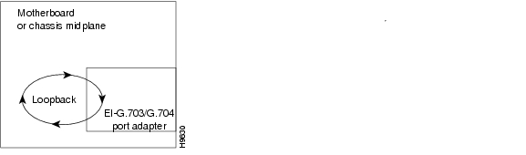
The E1-G.703/G.704 interface supports the same local loopback test as other (data communications) interfaces. Using the loopback functions, you can check the integrity of the physical data path between the motherboard (or chassis system) and the PA-4E1G with the loopback command. The loopback signal follows this path regardless of whether or not a cable is attached to the port.
Figure 4-1 shows the signal path of the loopback function. The no loopback command disables all loopback tests on the interface.
Note ![]() Because each E1-G.703/G.704 interface uses a default clock rate of 2.048 Mbps, you do not have to configure a clock signal on the interface before performing a loopback test.
Because each E1-G.703/G.704 interface uses a default clock rate of 2.048 Mbps, you do not have to configure a clock signal on the interface before performing a loopback test.
Figure 4-1 Loopback Path
 Feedback