Creating a New VXLAN EVPN Fabric with eBGP based Underlay
-
Choose Control > Fabric Builder.
The Fabric Builder screen appears. When you log in for the first time, the Fabrics section has no entries. After you create a fabric, it is displayed on the Fabric Builder screen, wherein a rectangular box represents each fabric.
A standalone or member fabric contains Switch_Fabric (in the Type field), the AS number (in the ASN field), and mode of replication (in the Replication Mode field).
The technology is for a fabric with eBGP Routed Fabric or eBGP VXLAN EVPN Fabric. The mode of replication is only applicable for the eBGP VXLAN EVPN fabric, and not eBGP Routed fabric.
-
Click Create Fabric. The Add Fabric screen appears.
The fields are explained:
Fabric Name - Enter the name of the fabric.
Fabric Template - From the drop-down menu, choose the Easy_Fabric_eBGP fabric template. The fabric settings for creating a standalone routed fabric comes up.
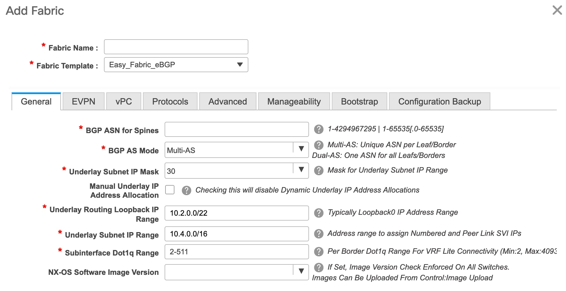
- The General tab is displayed by default. The fields in this tab are:
BGP ASN for Spines: Enter the BGP AS number of the fabric’s spine switches.
BGP AS Mode: Choose Multi-AS or Dual-AS.
In a Multi-AS fabric, the spine switches have a unique BGP AS number and each leaf switch has a unique AS number. If two leaf switches form a vPC switch pair, then they have the same AS number.
In a Dual-AS fabric, the spine switches have a unique BGP AS number and the leaf switches have a unique AS number.
The fabric is identified by the spine switch AS number.
Underlay Subnet IP Mask - Specifies the subnet mask for the fabric interface IP addresses.
Manual Underlay IP Address Allocation – Select this check box to disable Dynamic Underlay IP Address Allocations.
Underlay Routing Loopback IP Range: Specifies loopback IP addresses for the protocol peering.
Underlay Subnet IP Range: IP addresses for underlay P2P routing traffic between interfaces.
Subinterface Dot1q Range: Specifies the subinterface range when L3 sub interfaces are used.
NX-OS Software Image Version: Select an image from the drop-down list.
If you upload Cisco NX-OS software images through the image upload option, the uploaded images are listed in this field. If you select an image, the system checks if the switch has the selected version. If not, an error message is displayed. You can resolve the error by clicking on Resolve. The image management screen comes up and you can proceed with the ISSU option. Alternatively, you can delete the release number and save it later.
If you specify an image in this field, all switches in the fabric should run that image. If some devices do not run the image, a warning is prompted to perform an In-Service Software Upgrade (ISSU) to the specified image. Till all devices run the specified image, the deployment process will be incomplete.
If you want to deploy more than one type of software image on the fabric switches, don’t specify any image. If an image is specified, delete it.
-
Click EVPN. Most of the fields in this tab are auto-populated. The fields are:
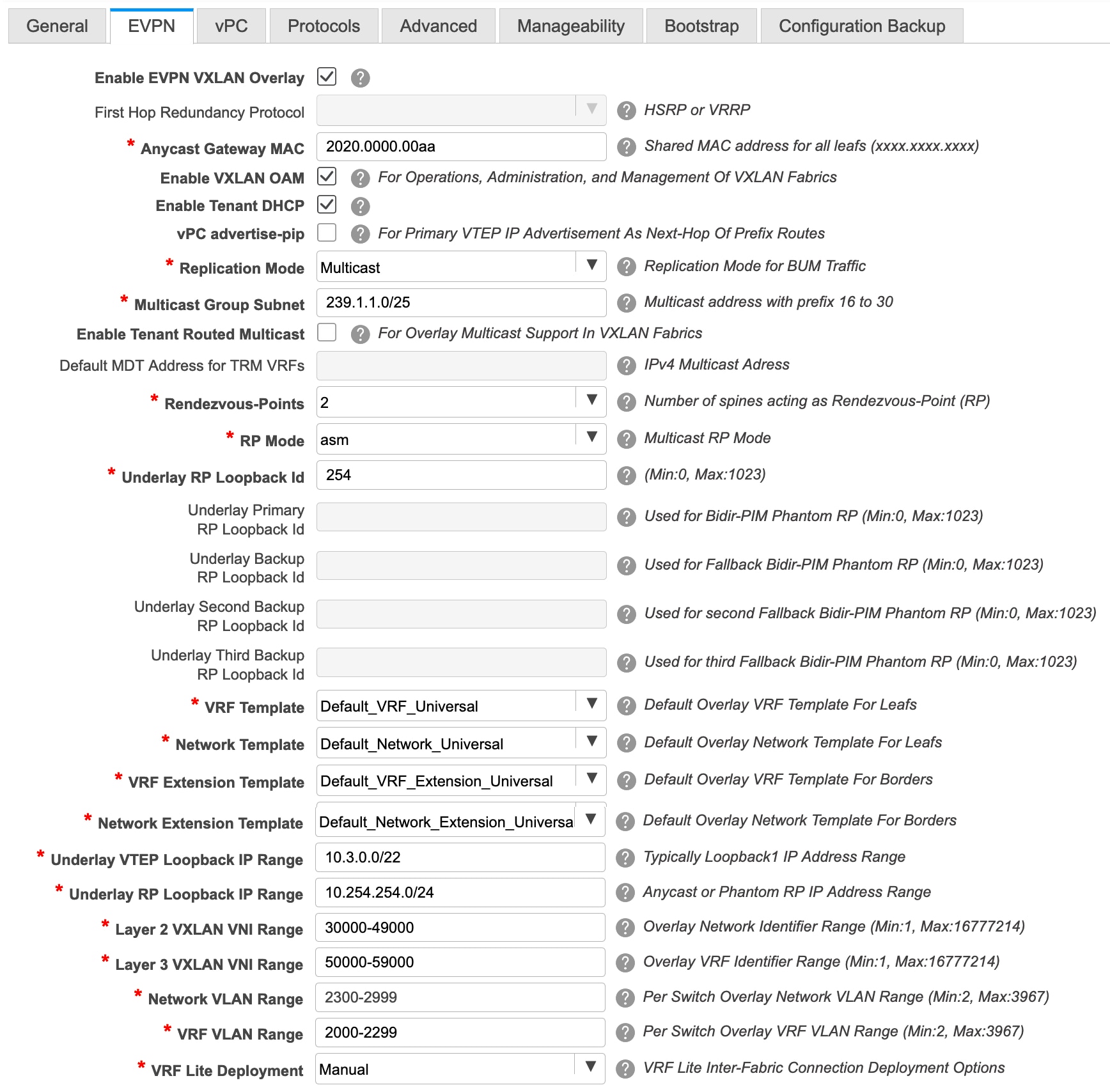
Enable EVPN VXLAN Overlay: Enables the VXLAN overlay provisioning for the fabric.
You can convert a routed fabric to a VXLAN enabled fabric by selecting this option. When the fabric is VXLAN enabled, you can create and deploy overlay networks or VRFs. The procedure for creating and deploying networks or VRFs is the same as in Easy_Fabric_11_1. For more information, see Creating and Deploying Networks and VRFs in the Control chapter in Cisco DCNM LAN Fabric Configuration Guide.
Routed Fabric: You must disable the Enable EVPN VXLAN Overlay field for Routed fabric (an IP fabric with no VXLAN encapsulation) creation. In a Routed Fabric, you can create and deploy networks. For more information, see Overview of Networks in a Routed Fabric.
Whether you create an eBGP Routed or eBGP VXLAN fabric, the fabric uses eBGP as the control plane to build intra-fabric connectivity. Links between spine and leaf switches are autoconfigured with point-to-point (p2p) numbered IP addresses with eBGP peering built on top.
If a network or a VRF is created in a fabric, you cannot switch between VXLAN EVPN mode and Routed Fabric mode by selecting the Enable EVPN VXLAN Overlay check box. You need to delete these networks or VRFs to change the fabric setting.
Note that Routed_Network_Universal Template is only applicable to a Routed Fabric. When you convert the routed fabric to EVPN VXLAN fabric, set the network template and network extension template to the ones defined for EVPN VLXAN: Default_Network_Universal and Default_Network_Extension_Universal. If you have a customized template for EVPN VXLAN fabric, you can also choose to use it.
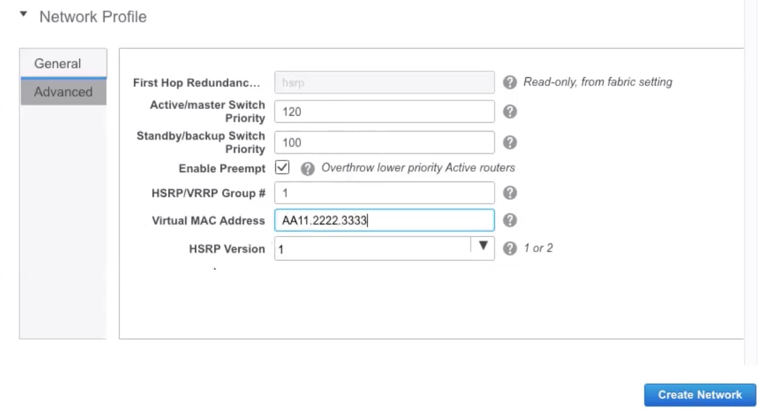
First Hop Redundancy Protocol: Specifies the FHRP protocol. Choose either hsrp or vrrp. This field is only applicable to a Routed Fabric.

Note
-
After a network has been created, you cannot change this fabric setting. You should delete all networks, and then change the FHRP setting.
-
The rest of the fields in the EVPN tab section are only applicable if you enable the EVPN VXLAN Overlay.
Anycast Gateway MAC: Anycast gateway MAC address for the leaf switches.
Enable VXLAN OAM: Enables the VXLAM OAM function for existing switches. This is enabled by default. Clear the check box to disable VXLAN OAM function.
If you want to enable the VXLAN OAM function on specific switches and disable on other switches in the fabric, you can use freeform configurations to enable OAM and disable OAM in the fabric settings.
Note
The VXLAN OAM feature in Cisco DCNM is only supported on a single fabric or site.
Enable Tenant DHCP: Enables tenant DHCP support.
vPC advertise-pip: Check the check box to enable the Advertise PIP feature.
Replication Mode : The mode of replication that is used in the fabric, Ingress Replication, or Multicast.
Multicast Group Subnet: IP address prefix used for multicast communication. A unique IP address is allocated from this group for each overlay network.
Enable Tenant Routed Multicast: Check the check box to enable Tenant Routed Multicast (TRM) as the fabric overlay multicast protocol.
Default MDT Address for TRM VRFs: The multicast address for Tenant Routed Multicast traffic is populated. By default, this address is from the IP prefix specified in the Multicast Group Subnet field. When you update either field, ensure that the TRM address is chosen from the IP prefix specified in Multicast Group Subnet.
Rendezvous-Points: Enter the number of spine switches acting as rendezvous points.
RP mode: Choose from the two supported multicast modes of replication, ASM (for Any-Source Multicast [ASM]) or BiDir (for Bidirectional PIM [BIDIR-PIM]). When you choose ASM, the BiDir related fields are not enabled. When you choose BiDir, the BiDir related fields are enabled.
Note
BIDIR-PIM is supported on Cisco's Cloud Scale Family platforms 9300-EX and 9300-FX/FX2, and software release 9.2(1) onwards.
Underlay RP Loopback ID: The loopback ID used for the rendezvous point (RP), for multicast protocol peering purposes in the fabric underlay. The default is 254.
The following fields are enabled if you choose bidir. Depending on the RP count, either 2 or 4 phantom RP loopback ID fields are enabled.
-
Underlay Primary RP Loopback ID: The primary loopback ID used for the phantom RP, for multicast protocol peering purposes in the fabric underlay.
-
Underlay Backup RP Loopback ID: The secondary (or backup) loopback ID used for the phantom RP, for multicast protocol peering purposes in the fabric underlay.
The following Loopback ID options are applicable only when the RP count is 4.
-
Underlay Second Backup RP Loopback ID: The second backup loopback ID used for the phantom RP, for multicast protocol peering purposes in the fabric underlay.
-
Underlay Third Backup RP Loopback ID: The third backup loopback ID used for the phantom RP, for multicast protocol peering purposes in the fabric underlay.
VRF Template and VRF Extension Template: Specify the VRF template for creating VRFs, and the VRF extension template for enabling VRF extension to other fabrics.
Network Template and Network Extension Template: Specify the network template for creating networks, and the network extension template for extending networks to other fabrics.
Underlay VTEP Loopback IP Range: Specifies the loopback IP address range for VTEPs.
Underlay RP Loopback IP Range: Specifies the anycast or phantom RP IP address range.
Layer 2 VXLAN VNI Range and Layer 3 VXLAN VNI Range: Specify the VXLAN VNI IDs for the fabric.
Network VLAN Range and VRF VLAN Range: VLAN ranges for the Layer 3 VRF and overlay network.
VRF Lite Deployment: Specifies the VRF Lite method for extending inter fabric connections. Only the 'Manual' option is supported.
-
-
Click vPC. The fields in the tab are:
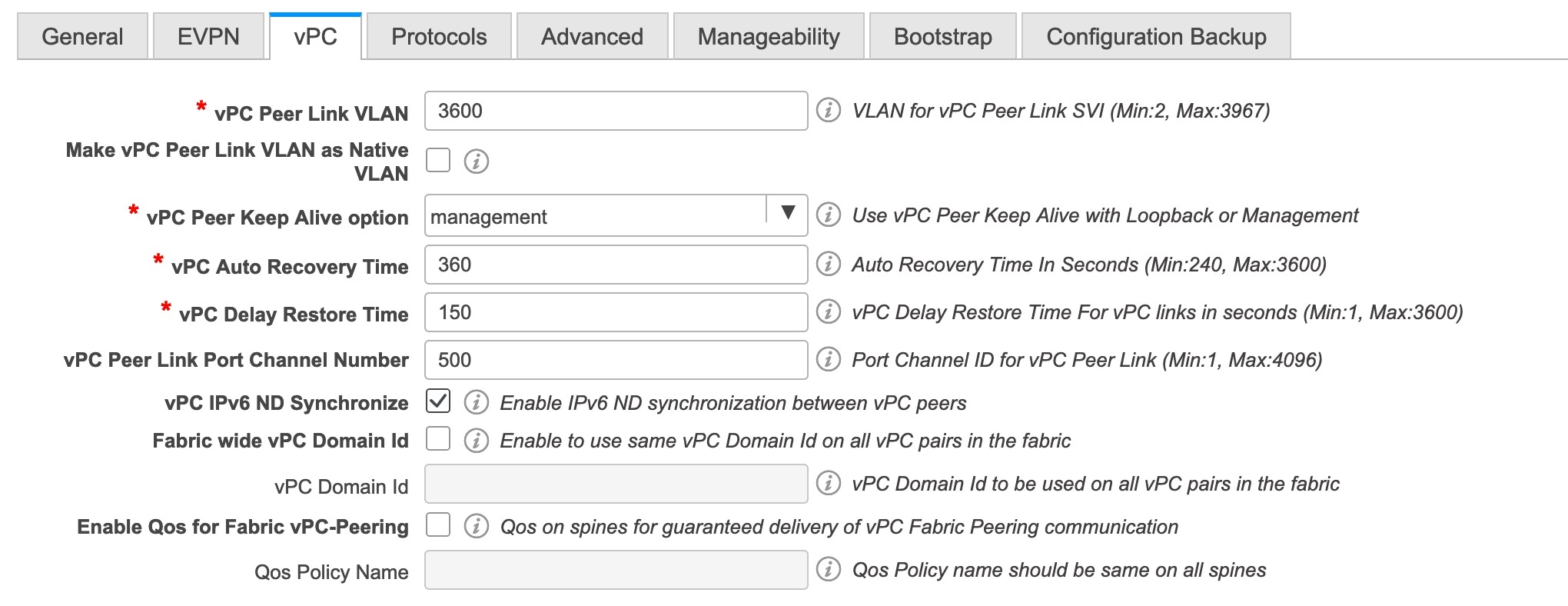
vPC Peer Link VLAN: VLAN used for the vPC peer link SVI.
Make vPC Peer Link VLAN as Native VLAN - Enables vPC peer link VLAN as Native VLAN.
vPC Peer Keep Alive option: Choose the management or loopback option. If you want to use IP addresses assigned to the management port and the management VRF, choose management. If you use IP addresses assigned to loopback interfaces (and a non-management VRF), choose loopback. If you use IPv6 addresses, you must use loopback IDs.
vPC Auto Recovery Time: Specifies the vPC auto recovery time-out period in seconds.
vPC Delay Restore Time: Specifies the vPC delay restore period in seconds.
vPC Peer Link Port Channel Number - Specifies the Port Channel ID for a vPC Peer Link. By default, the value in this field is 500.
vPC IPv6 ND Synchronize: Enables IPv6 Neighbour Discovery synchronization between vPC switches. The check box is enabled by default. Clear the check box to disable the function.
Fabric wide vPC Domain Id: Enables the usage of same vPC Domain Id on all vPC pairs in the fabric. When you select this field, the vPC Domain Id field is editable.
vPC Domain Id - Specifies the vPC domain ID to be used on all vPC pairs.
Enable Qos for Fabric vPC-Peering - Enable QoS on spines for guaranteed delivery of vPC Fabric Peering communication.
Qos Policy Name - Specifies QoS policy name that should be same on all spines.
-
Click the Protocols tab. The fields in the tab are:
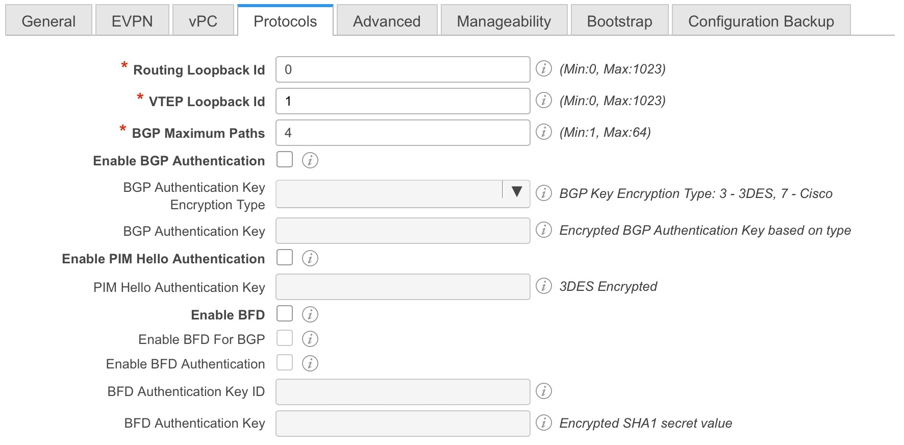
Routing Loopback Id - The loopback interface ID is populated as 0 by default. It is used as the BGP router ID.
VTEP Loopback Id - The loopback interface ID is populated as 1 since loopback1 is usually used for the VTEP peering purposes.
BGP Maximum Paths - Specifies the BGP maximum paths.
Enable BGP Authentication: Select the check box to enable BGP authentication. Deselect the check box to disable it. If you enable this field, the BGP Authentication Key Encryption Type and BGP Authentication Key fields are enabled.
BGP Authentication Key Encryption Type: Choose the 3 for 3DES encryption type, or 7 for Cisco encryption type.
BGP Authentication Key: Enter the encrypted key based on the encryption type.
Note
Plain text passwords are not supported. Login to the switch, retrieve the encrypted key and enter it in the BGP Authentication Key field. Refer the Retrieving the Authentication Key section for details.
Enable PIM Hello Authentication: Enables the PIM hello authentication.
PIM Hello Authentication Key: Specifies the PIM hello authentication key.
Enable BFD: Select the check box to enable feature bfd on all switches in the fabric. This feature is valid only on IPv4 underlay and the scope is within a fabric.
From Cisco DCNM Release 11.3(1), BFD within a fabric is supported natively. The BFD feature is disabled by default in the Fabric Settings. If enabled, BFD is enabled for the underlay protocols with the default settings. Any custom required BFD configurations must be deployed via the per switch freeform or per interface freeform policies.
The following config is pushed after you select the Enable BFD check box:
feature bfd
Note
After you upgrade from DCNM Release 11.2(1) with BFD enabled to DCNM Release 11.3(1), the following configs are pushed on all P2P fabric interfaces:
no ip redirects
no ipv6 redirects
For information about BFD feature compatibility, refer your respective platform documentation and for information about the supported software images, see Compatibility Matrix for Cisco DCNM.
Enable BFD for BGP: Select the check box to enable BFD for the BGP neighbor. This option is disabled by default.
Enable BFD Authentication: Select the check box to enable BFD authentication. If you enable this field, the BFD Authentication Key ID and BFD Authentication Key fields are editable.
BFD Authentication Key ID: Specifies the BFD authentication key ID for the interface authentication.
BFD Authentication Key: Specifies the BFD authentication key.
For information about how to retrieve the BFD authentication parameters, see Retrieving the Encrypted BFD Authentication Key, in Cisco DCNM LAN Fabric Configuration Guide.
-
Click the Advanced tab. The fields in the tab are:
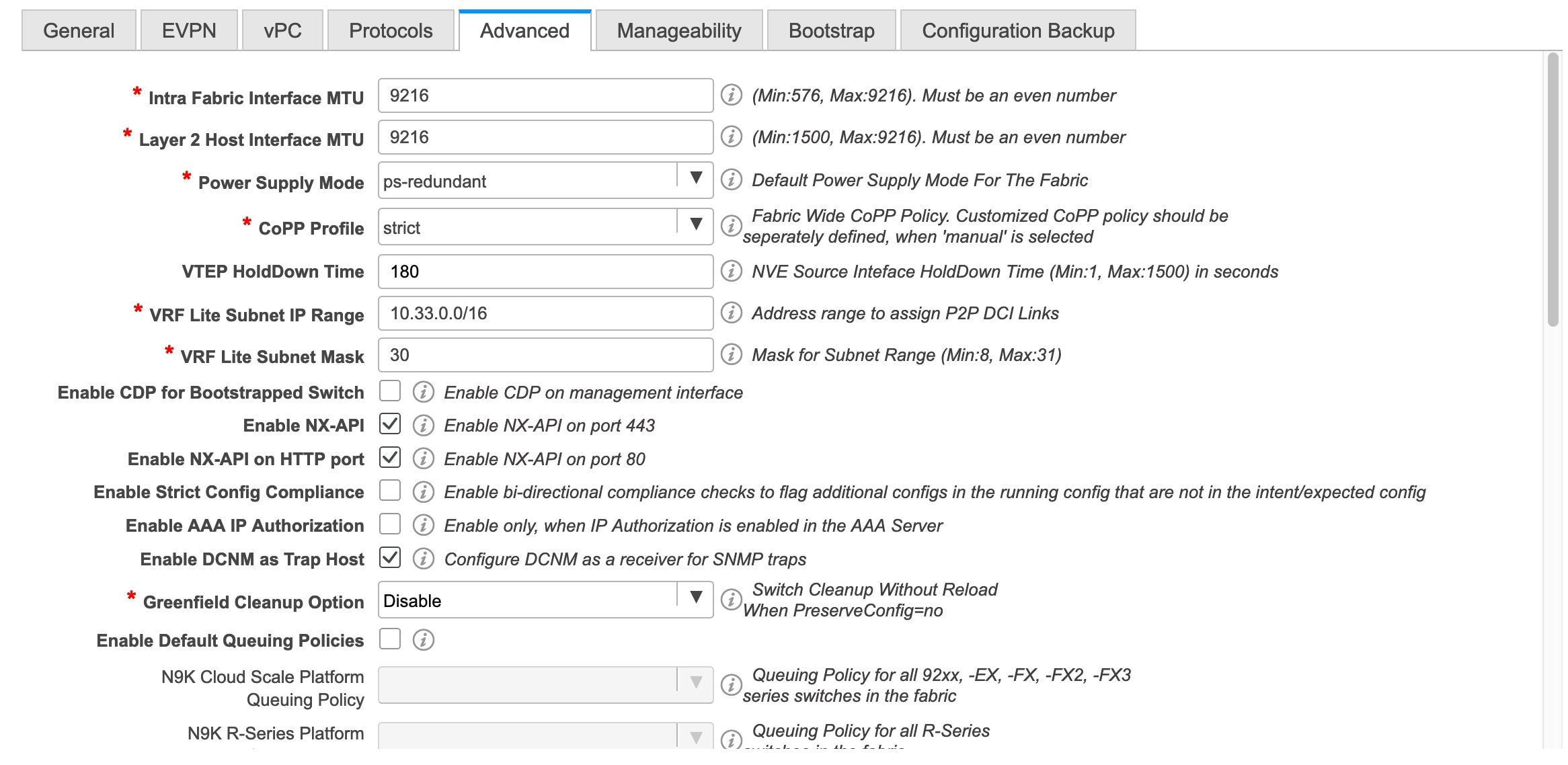
Intra Fabric Interface MTU - Specifies the MTU for the intra fabric interface. This value should be an even number.
Layer 2 Host Interface MTU - Specifies the MTU for the layer 2 host interface. This value should be an even number.
Power Supply Mode: Choose the appropriate power supply mode.
CoPP Profile: Choose the appropriate Control Plane Policing (CoPP) profile policy for the fabric. By default, the strict option is populated.
VTEP HoldDown Time - Specifies the NVE source interface hold down time.
VRF Lite Subnet IP Range and VRF Lite Subnet Mask – These fields are populated with the DCI subnet details. Update the fields as needed.
Enable CDP for Bootstrapped Switch - Select the check box to enable CDP for bootstrapped switch.
Enable NX-API - Specifies enabling of NX-API on HTTPS. This check box is checked by default.
Enable NX-API on HTTP - Specifies enabling of NX-API on HTTP. Enable this check box and the Enable NX-API check box to use HTTP. This check box is checked by default. If you uncheck this check box, the applications that use NX-API and supported by Cisco DCNM, such as Endpoint Locator (EPL), Layer 4-Layer 7 services (L4-L7 services), VXLAN OAM, and so on, start using the HTTPS instead of HTTP.
Note
If you check the Enable NX-API check box and the Enable NX-API on HTTP check box, applications use HTTP.
Enable Strict Config Compliance - Enable the Strict Config Compliance feature by selecting this check box.
For Strict Configuration Compliance, see Enhanced Monitoring and Monitoring Fabrics Guide.
Note
If Strict Config Compliance is enabled in a fabric, you cannot deploy Network Insights for Resources on Cisco DCNM.
Enable AAA IP Authorization - Enables AAA IP authorization, when IP Authorization is enabled in the AAA Server
Enable DCNM as Trap Host - Select this check box to enable DCNM as a trap host.
Enable TCAM Allocation: TCAM commands are automatically generated for VXLAN and vPC Fabric Peering when enabled.
Greenfield Cleanup Option: Enable the switch cleanup option for greenfield switches without a switch reload. This option is typically recommended only for the data center environments with the Cisco Nexus 9000v Switches.
Enable Default Queuing Policies: Check this check box to apply QoS policies on all the switches in this fabric. To remove the QoS policies that you applied on all the switches, uncheck this check box, update all the configurations to remove the references to the policies, and save and deploy. From Cisco DCNM Release 11.3(1), pre-defined QoS configurations are included that can be used for various Cisco Nexus 9000 Series Switches. When you check this check box, the appropriate QoS configurations are pushed to the switches in the fabric. The system queuing is updated when configurations are deployed to the switches. You can perform the interface marking with defined queuing policies, if required, by adding the required configuration to the per interface freeform block.
Review the actual queuing policies by opening the policy file in the template editor. From Cisco DCNM Web UI, choose Control > Template Library. Search for the queuing policies by the policy file name, for example, queuing_policy_default_8q_cloudscale. Choose the file and click the Modify/View template icon to edit the policy.
See the Cisco Nexus 9000 Series NX-OS Quality of Service Configuration Guide for platform specific details.
N9K Cloud Scale Platform Queuing Policy: Choose the queuing policy from the drop-down list to be applied to all Cisco Nexus 9200 Series Switches and the Cisco Nexus 9000 Series Switches that ends with EX, FX, and FX2 in the fabric. The valid values are queuing_policy_default_4q_cloudscale and queuing_policy_default_8q_cloudscale. Use the queuing_policy_default_4q_cloudscale policy for FEXes. You can change from the queuing_policy_default_4q_cloudscale policy to the queuing_policy_default_8q_cloudscale policy only when FEXes are offline.
N9K R-Series Platform Queuing Policy: Choose the queuing policy from the drop-down list to be applied to all Cisco Nexus switches that ends with R in the fabric. The valid value is queuing_policy_default_r_series.
Other N9K Platform Queuing Policy: Choose the queuing policy from the drop-down list to be applied to all other switches in the fabric other than the switches mentioned in the above two options. The valid value is queuing_policy_default_other.
Enable MACsec: Enables MACsec for the fabric. For more information, see MACsec Support in Easy Fabric and eBGP Fabric.
Leaf Freeform Config: Add CLIs that should be added to switches that have the Leaf, Border, and Border Gateway roles.
Spine Freeform Config - Add CLIs that should be added to switches with a Spine, Border Spine, and Border Gateway Spine roles.
Intra-fabric Links Additional Config - Add CLIs that should be added to the intra-fabric links.
-
Click the Manageability tab.
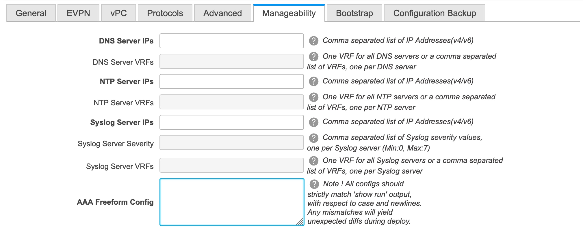
The fields in this tab are:
DNS Server IPs - Specifies the comma separated list of IP addresses (v4/v6) of the DNS servers.
DNS Server VRFs - Specifies one VRF for all DNS servers or a comma separated list of VRFs, one per DNS server.
NTP Server IPs - Specifies comma separated list of IP addresses (v4/v6) of the NTP server.
NTP Server VRFs - Specifies one VRF for all NTP servers or a comma separated list of VRFs, one per NTP server.
Syslog Server IPs – Specifies the comma separated list of IP addresses (v4/v6) IP address of the syslog servers, if used.
Syslog Server Severity – Specifies the comma separated list of syslog severity values, one per syslog server. The minimum value is 0 and the maximum value is 7. To specify a higher severity, enter a higher number.
Syslog Server VRFs – Specifies one VRF for all syslog servers or a comma separated list of VRFs, one per syslog server.
AAA Freeform Config – Specifies the AAA freeform configs.
If AAA configs are specified in the fabric settings, switch_freeform PTI with source as UNDERLAY_AAA and description as “AAA Configurations” will be created.
-
Click the Bootstrap tab.
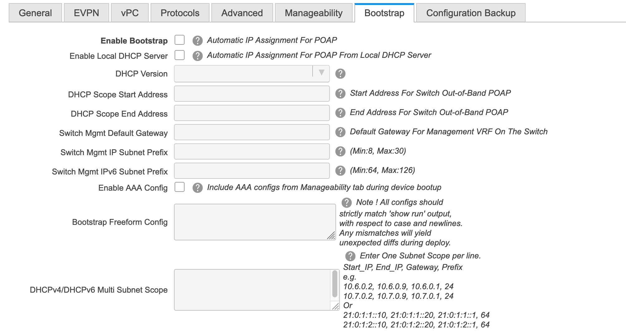
Enable Bootstrap - Select this check box to enable the bootstrap feature.
After you enable bootstrap, you can enable the DHCP server for automatic IP address assignment using one of the following methods:
-
External DHCP Server: Enter information about the external DHCP server in the Switch Mgmt Default Gateway and Switch Mgmt IP Subnet Prefix fields.
-
Local DHCP Server: Enable the Local DHCP Server checkbox and enter details for the remaining mandatory fields.
Enable Local DHCP Server - Select this check box to initiate enabling of automatic IP address assignment through the local DHCP server. When you select this check box, the DHCP Scope Start Address and DHCP Scope End Address fields become editable.
If you do not select this check box, DCNM uses the remote or external DHCP server for automatic IP address assignment.
DHCP Version – Select DHCPv4 or DHCPv6 from this drop-down list. When you select DHCPv4, the Switch Mgmt IPv6 Subnet Prefix field is disabled. If you select DHCPv6, the Switch Mgmt IP Subnet Prefix is disabled.
Note
Cisco DCNM IPv6 POAP is not supported with Cisco Nexus 7000 Series Switches. Cisco Nexus 9000 and 3000 Series Switches support IPv6 POAP only when switches are either L2 adjacent (eth1 or out-of-band subnet must be a /64) or they are L3 adjacent residing in some IPv6 /64 subnet. Subnet prefixes other than /64 are not supported.
DHCP Scope Start Address and DHCP Scope End Address - Specifies the first and last IP addresses of the IP address range to be used for the switch out of band POAP.
Switch Mgmt Default Gateway: Specifies the default gateway for the management VRF on the switch.
Switch Mgmt IP Subnet Prefix: Specifies the prefix for the Mgmt0 interface on the switch. The prefix should be between 8 and 30.
DHCP scope and management default gateway IP address specification - If you specify the management default gateway IP address 10.0.1.1 and subnet mask 24, ensure that the DHCP scope is within the specified subnet, between 10.0.1.2 and 10.0.1.254..
Switch Mgmt IPv6 Subnet Prefix - Specifies the IPv6 prefix for the Mgmt0 interface on the switch. The prefix should be between 112 and 126. This field is editable if you enable IPv6 for DHCP.
Enable AAA Config – Select this check box to include AAA configs from the Manageability tab during device bootup.
Bootstrap Freeform Config - (Optional) Enter additional commands as needed. For example, if you are using AAA or remote authentication related configurations, you need to add these configurations in this field to save the intent. After the devices boot up, they contain the intent defined in the Bootstrap Freeform Config field.
Copy-paste the running-config to a freeform config field with correct indentation, as seen in the running configuration on the NX-OS switches. The freeform config must match the running config. For more information, see Resolving Freeform Config Errors in Switches in Enabling Freeform Configurations on Fabric Switches.
DHCPv4/DHCPv6 Multi Subnet Scope - Specifies the field to enter one subnet scope per line. This field is editable after you check the Enable Local DHCP Server check box.
The format of the scope should be defined as:
DHCP Scope Start Address, DHCP Scope End Address, Switch Management Default Gateway, Switch Management Subnet Prefix
For example: 10.6.0.2, 10.6.0.9, 10.6.0.1, 24
-
-
Click the Configuration Backup tab. The fields on this tab are:
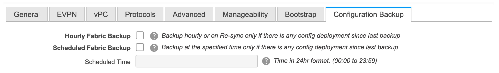
Hourly Fabric Backup: Select the check box to enable an hourly backup of fabric configurations and the intent.
You can enable an hourly backup for fresh fabric configurations and the intent as well. If there is a configuration push in the previous hour, DCNM takes a backup.
Intent refers to configurations that are saved in DCNM but yet to be provisioned on the switches.
Scheduled Fabric Backup: Check the check box to enable a daily backup. This backup tracks changes in running configurations on the fabric devices that are not tracked by configuration compliance.
Scheduled Time: Specify the scheduled backup time in a 24-hour format. This field is enabled if you check the Scheduled Fabric Backup check box.
Select both the check boxes to enable both back up processes.
The backup process is initiated after you click Save.
Note
Hourly and scheduled backup processes happen only during the next periodic configuration compliance activity, and there can be a delay of up to an hour. To trigger an immediate backup, do the following:
-
Choose Control > Fabric Builder. The Fabric Builder screen comes up.
-
Click within the specific fabric box. The fabric topology screen comes up.
-
From the Actions panel at the left part of the screen, click Re-Sync Fabric.
You can also initiate the fabric backup in the fabric topology window. Click Backup Now in the Actions pane.
Click Save after filling and updating relevant information.
-
VXLAN Fabric With eBGP Underlay – Pointers
-
Deploy the leaf overlay and underlay policies on all leaf switches at once, since they have a common AS number.
-
Brownfield migration is not supported for eBGP fabric.
-
You cannot change the leaf switch AS number after it is created and the Save & Deploy operation is executed. You need to delete the leaf_bgp_asn policy and execute the Save & Deploy operation to remove BGP configuration related to this AS first. Then, you can add the leaf_bgp_asn policy with the new AS number.
-
If you want to switch between Multi-AS and Dual-AS modes, remove all manually added BGP policies (including leaf_bgp_asn on the leaf switch and the ebgp overlay policies), and execute the Save & Deploy operation before the mode change.
-
You cannot change or delete the leaf switch leaf_bgp_asn policy if there are ebgp overlay policies present on the device. You need to delete the ebgp overlay policy first, and then delete the leaf_bgp_asn policy.
-
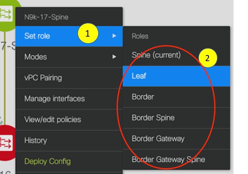
The supported roles are leaf, spine, and border leaf.
-
On the border device, VRF-Lite is supported with manual mode. There is no Multi-Site support for external connectivity.
-
TRM is supported.
-
You must apply policies on the leaf and spine switches for a functional fabric.
-
For a VXLAN enabled fabric, you can create and deploy overlay networks and VRFs the same way as in Easy Fabric. For more information, see Creating and Deploying Networks and VRFs in the Control chapter in Cisco DCNM LAN Fabric Configuration Guide.
 Feedback