Cisco Service Control Product Installation Guide, Release 5.0.x
Available Languages
Table of Contents
Cisco Service Control Product Installation Guide, Release 5.0.x
Overview of the Cisco Service Control Solution Cisco Service Control Components
Cisco Service Control Solution Topology Cisco SCE 10000 Platform Topologies
Multi-Gigabit Service Control Platform (MGSCP) Topology
Installing the Cisco SCE 10000 Platform
Installing the Subscriber Manager
Installing the Collection Manager
Ports Used by the Collection Manager Software
Installing Collection Manager Software
Installing the Cisco SCA BB Application
How to Verify that the Cisco SCE Platform is Running a Compatible Version of the OS
How to Verify that the Subscriber Manager is Running a Compatible Version
How to Install the Cisco SCA BB Console
How to Install the Cisco SCA BB Configuration Utilities
Installing the Application and Protocol Pack on the Cisco SCE Platform
How to Install Files on the Cisco SCE Platform
Initial Configuration of the Cisco SCE 10000 Platform
Initial Cisco SCA BB Configuration
How to Use the Usage Analysis Wizard to Define the Default Site
Configuring the Subscriber Manager
System Requirements and Prerequisites Subscriber Manager System Requirements
Cisco Service Control Collection Manager System Requirements
Obtaining Documentation and Submitting a Service Request Cisco Service Control Product Installation Guide, Release 5.0.x
Overview of the Cisco Service Control Solution
Cisco Service Control Solution Topology
System Requirements and Prerequisites
Overview of the Cisco Service Control Solution
This section introduces the components of the Cisco Service Control solution and gives a high-level explanation of the entire installation process.
Cisco Service Control Components
The Cisco Service Control solution consists of five main components:
- Cisco Service Control Engine (SCE) platform—A flexible, powerful, and dedicated network-usage monitor that is custom-built to analyze and report on network transactions at the application level.
For complete information about the installation and initial configuration of the Cisco SCE platform, see the Cisco SCE Platform Installation Guides and Configuration Guides .
- Cisco Service Control Application for Broadband (SCA BB)—An application that creates a service configuration file containing settings for traffic classification, accounting, and reporting, and applies it to a Cisco SCE platform. Cisco SCA BB provides tools to automate the distribution of these configuration files to Cisco SCE platforms. This simple, standards-based approach makes it easy to manage multiple devices in a large network.
For complete information about the installation and operation of Cisco SCA BB, see the Cisco Service Control Application for Broadband (SCA BB) User Guide .
- Service Control Management Suite (SCMS) Subscriber Manager—A middleware software component used when dynamic binding of subscriber information and policies is required. The Subscriber Manager manages subscriber information and provisions it in real time to multiple Cisco SCE platforms. The Subscriber Manager stores subscriber policy information internally, and acts as a stateful bridge between the authentication, authorization, and accounting (AAA) system (such as RADIUS and DHCP) and the Cisco SCE platforms.
For more information about the installation and operation of the Subscriber Manager, see the Cisco Service Control Management Suite Subscriber Manager User Guide.
Quota Manager is an optional component of the Subscriber Manager. It enables Cisco Control solution providers to manage subscriber quota across subscriber sessions with a high degree of flexibility.
For more information about the installation and operation of the Quota Manager, see the Cisco Service Control Management Suite Quota Manager User Guide.
Virtual Link Manager (VLM) is a component of the Subscriber Manager that enables Cisco Service Control solution providers to monitor and control individual subscriber links separately. For this, VLM creates a single policy with tier-differentiated packages, as also a number of virtual links, and then assigns subscribers to these virtual links. For more information, see the Cisco Service Control for Managing Remote Cable MSO Links Solution Guide .
- SCMS Collection Manager—Implementation of a collection system that receives Raw Data Records (RDRs) from one or more Cisco SCE platforms. The Collection Manager collects usage information and statistics, and stores them in a database. The Collection Manager also converts subscriber usage information and statistics into simple text-based files for further processing and collection by external systems.
For more information about the installation and operation of the Collection Manager, see the Cisco Service Control Management Suite Collection Manager User Guide .
- Insight Reporter—Cisco Insight Reporter is a software platform based on web 2.0 user experience standards, designed to collect and present reports, charts, and statistics about the traffic data collected by Cisco SCE devices.
Together, the Cisco SCE platform, the SCMS Collection Manager, the SCMS Subscriber Manager, and Cisco Insight are designed to support detailed classification, analysis, reporting, and control of IP network traffic. The SCMS Collection Manager and the SCMS Subscriber Manager are optional components; not all deployments of the Cisco Service Control solution require them. The following sites may not require all these components:
Options and Versions
The Cisco SCE platform is available in the following version:
The platform version is available with either AC or DC power.

Note
In general, this guide contains instructions for installing the Cisco SCE 10000 platform. In general, this guide contains instructions for installing the Cisco SCE 10000 platform.
Cisco SCA BB is not available in different versions.
The SCMS Subscriber Manager is available in the following version:
SCMS Subscriber Manager versions are available with these options:
The SCMS Collection Manager is available in the Linux version
The SCMS Collection Manager versions is available with the following option:
System Installation Overview
Figure 1 shows the order of in which the Cisco Service Control solution must be installed.
Figure 1 Installing the Complete Cisco Service Control Solution

To install the complete Cisco Service Control solution, complete these steps:
Step 1
Step 2
Step 3
Step 4
Step 5
Step 6
Step 7
Cisco Service Control Solution Topology
This section describes the possible deployment topologies of the Cisco Service Control solution.
Note
Overall System Topology
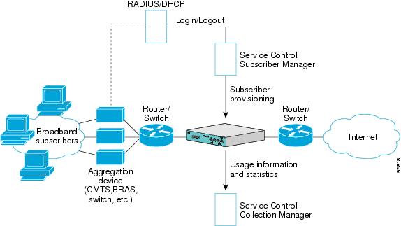
Figure 2 illustrates the general topology of the Cisco Service Control solution.
The SCE platform monitors traffic flow.
- Vertical flow—Represents transmission of RDRs from the Cisco SCE platform to the SCMS Collection Manager.
The SCMS Subscriber Manager provides subscriber data. This flow allows Cisco SCA BB to conduct subscriber-level analysis and control.
Figure 2 Flow of Information in SCA BB
Cisco SCE 10000 Platform Topologies
The Cisco SCE 10000 platform is an ideal solution for dual links with load sharing and asymmetrical routing and support for fail-over between two Cisco SCE platforms.
Cisco SCE 10000 is built to support wire-speed processing of full-duplex 10 GBE streams. The Cisco SCE 10000 can, therefore, be deployed in a multilink environment, in several topologies:
- Single Cisco SCE 10000 topology—Enables processing of both upstream and downstream paths of a bidirectional flow, even if these paths traverse different links.
- Multi-Gigabit Service Control Platform (MGSCP) topology—Provides scalability. The Cisco SCE 10000 platform supports the option to connect multiple SCE platforms to a Cisco 7600 Series Router or a Cisco ASR 9000 Series Router to perform load balancing between the platforms.
Physical Topologies
These are the descriptions of the physical topologies that Cisco SCE 10000 supports:
Single Cisco SCE 10000 Topologies
A single Cisco SCE 10000 supports both single 10GBE link and dual 10GBE link topologies.
Single Link: Inline Topology
Typically, Cisco SCE 10000 is connected in a full-duplex 10GBE link between two devices (Router, broadband remote access server, and so on). When Cisco SCE 10000 is installed inline, it physically resides on the data link between the subscribers and the network.
Multi Link: Inline Installation
In this topology, a Cisco SCE 10000 is connected inline in four links and with eight 10 GBE interfaces.
Single Link: Receive-Only Topology
In this topology, an optical splitter resides physically on the 10GBE link between the subscribers and the network. The traffic passes through the optical splitter, which splits the traffic to Cisco SCE 10000. As a result, Cisco SCE 10000 only receives traffic and does not transmit.
In an optical splitter topology, Cisco SCE 10000 enables only the traffic monitoring functionality.
Note
MultiLink: Receive-Only Topology
In this topology, a Cisco SCE 10000 is connected in receive-only mode tn four links and with eight 10 GBE interfaces.
As with the dual link, inline topology, this topology completely overcomes the problem of asymmetrical routing.When implementing receive-only topologies with a switch, the switch must support the SPAN functionality that includes separation between ingress and egress traffic and multiple SPAN ports destinations.
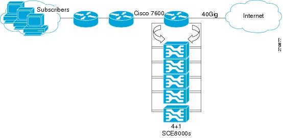
Multi-Gigabit Service Control Platform (MGSCP) Topology
In this topology, multiple Cisco SCE 10000 platforms are connected to a Cisco 7600 Series router, which acts as a dispatcher between the platforms (see Figure 3 ). The router contains two EtherChannels (ECs), one for the subscriber side and one for the network side, that perform load balancing for the Cisco SCE platform traffic. Traffic enters the first router, is distributed between the Cisco SCE platforms by the subscriber-side EC, and then returns to the router so that it can be forwarded to its original destination.
Note You can also use Cisco ASR 9000 series router for the same solution.
There are a number of variables to be considered in the MGSCP topology, two of which include:
Type of SCE Platform Redundancy
There are two types of SCE platform redundancy:
All the ports in the EtherChannel and all the Cisco SCE platforms are active. If a failure occurs on one of the Cisco SCE platforms, the links on the related ports in the EC go down and the EC automatically excludes them from load distribution. The load is then distributed among the active Cisco SCE platforms.
N Cisco SCE platforms are active and one platform is on standby. The EC ports connected to the standby Cisco SCE platform must be configured as standby ports. If one Cisco SCE platform fails, the EtherChannel ports connected to the failing SCE platform are shut and the standby EtherChannel ports, connected to the standby SCE platform are activated.
Note The standby SCE platform must be connected to the two highest-numbered ports, because EC behavior automatically designates these ports as the standby ports.
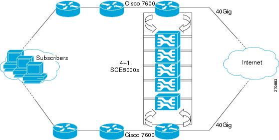
Redundant Cisco 7600 Series Router
Two Cisco 7600 Series routers can be used to provide network redundancy (see Figure 4 ).
In this topology, one link on each Cisco SCE 10000 platform is connected to each router. Therefore, one SCE platform is required for each link.
Figure 4 MGSCP with Redundant Router
System Installation
This chapter describes the system installation of the Cisco Service Control solution.
Installing the Cisco SCE 10000 Platform
To install the Cisco SCE 10000 platform, complete the following steps. (For more information, see the Cisco SCE 10000 Installation and Configuration Guide .)
Step 1
Step 2
Step 3
Step 4
Step 5
Cisco SCE 10000 Connectivity
Table 1 and Table 2 summarize Cisco SCE 10000 connectivity for the basic topologies.
Note
MGSCP Topologies
In an MGSCP deployment, the exact cabling scheme depends on the number and arrangement of ports in the EtherChannel in the Cisco 7600 Series router. It is, therefore, not possible to provide exact cabling schemes.
The following general guidelines are applicable during the process of designing the cabling scheme:
- Because there are four links per Cisco SCE 10000 platform, the minimum number of platforms required is one fourth the number of links used.
- Each link corresponds to one port on the EtherChannel on the Cisco 7600 Series router. Each EtherChannel supports a maximum of eight ports. Therefore, if all eight EtherChannel ports are configured, four Cisco SCE 10000 platforms are required.
- For N+1 redundancy, two ports (connected to the standby platform) must be configured as standby ports on both EtherChannels. Therefore, for N+1 redundancy, one router and five Cisco SCE 10000 platforms will be used to support eight links.
- If two Cisco 7600 Series routers are used (for network redundancy), one link on each Cisco SCE 10000 platform is connected to each router. This topology requires twice the number of Cisco SCE 10000 platforms, one platform for each link.
–
–
When cabling to the EtherChannel, follow these guidelines:
- The Cisco SCE platform ports must be connected to the EtherChannel ports in the same order on both sides.
- The EtherChannel ports must be sorted in ascending order by their physical interface numbers.
- In a topology with two Cisco 7600 Series routers, the order of connection to the EtherChannel ports must be the same on both routers. For both routers to send the traffic of a given subscriber to the same Cisco SCE platform, the Cisco SCE platforms must be connected to both routers in the same order (one Cisco SCE platform connected to the first link on both routers, another Cisco SCE platform connected to the second link on both routers, and so on).
Installing the Subscriber Manager
This section describes how to install Subscriber Manager, Release 5.0.x, on a computer running Red Hat Linux.
For more information, see the Cisco SCMS Subscriber Manager User Guide .
To install Subscriber Manager, Release 5.0.x, complete these steps:
Step 1
Step 2
Set the system memory configuration requirements according to the maximum number of subscribers. See the “Installation Procedure” section in the “Installation and Upgrading” chapter of the Cisco Service Control Management Suite Subscriber Manager User Guide .
Step 3
TimesTen requires that certain changes be made in the OS kernel configuration file:
These changes increase the shared memory and semaphore resources on the machine from their defaults. See the “Installation Procedure” section in the “Installation and Upgrading” chapter of the Cisco Service Control Management Suite Subscriber Manager User Guide .
Step 4
Note We recommend that you edit the install-def.cfg file if you do not want the default parameter values to be used.
The install-def.cfg file contains several parameters that can be configured before you install the Subscriber Manager. The installation routine copies these parameters to the relevant Subscriber Manager configuration file. By default, all the parameters are commented and the default values are used.
Table 3 lists the parameters of the install-def.cfg file.
Step 5
Note You can customize the install-sm.sh script.
Note If the /etc/motd file exists, it is not possible to run the script. Move or remove the /etc/motd file before you run the install-sm.sh script.
From your workstation shell prompt, move to the directory to which the distribution file was extracted and run the install-sm.sh script. See the “Installation Procedure” section of the “Installation and Upgrading” chapter of Cisco Service Control Management Suite Subscriber Manager User Guide .
Step 6
After the installation script runs successfully, set the password for the pcube user by running the # passwd pcube command.
Note We recommend that you note down this password for future use.
Step 7
Step 8
It is necessary to add a user for PRPC authentication because Cisco SCA BB requires a username and password when connecting to the Subscriber Manager.
To add a user for PRPC authentication, use the p3rpc command-line utility. For example:
Installing the Collection Manager
This section describes how to install the Collection Manager, on a computer running Red Hat Linux:
For more information, see the Cisco Service Control Management Suite Collection Manager User Guide .
Ports Used by the Collection Manager Software
Table 4 describes the TCP/UDP ports on which the Collection Manager software and associated components (such as the Sybase database) listen. This table helps the network administrator understand the behavior of the software and its adherence to the security policy.
The ports that are listed are those ports on which the device listens constantly. Allow access on these port numbers; otherwise, certain operations may fail.
Some operations (such as file transfer) cause a device to open ports, other than those listed, temporarily; however, these ports close automatically after the operation ends.
Installing Collection Manager Software
Use the install-cm.sh script to install the Collection Manager server.
The usage message for the install-cm.sh script is:
The description of the options is as follows:
For information about the actions performed by the install-cm.sh script, see the Cisco Service Control Management Suite Collection Manager User Guide .
Install the Collection Manager server by performing the following procedure:
Step 1
Step 2
After running the script, a user-driven configuration manager presents the user with options for the basic configuration of the Collection Manager.
Step 3
Step 4
Step 5
a.
For more information, see the “Configuring Databases” section in the “Managing the Collection Manager” chapter of the Cisco Service Control Management Suite Collection Manager User Guide .
b.
You will see the following text:
Step 6
Step 7
The most basic installation of Collection Manager software is done.
Note A failed connection results in the user being prompted to re-enter the DB information.
Note After the user configures the requested database options, the dbinfo.vm file updates for the RDR database configuration details, the Cisco IOS Flexible NetFlow database configuration details.
Note We recommend that you set up separate databases for each platform.
Step 8
We recommend that you maintain a record of the password.
Step 9
This is a list of supported external databases:
If you are using an external database, start it according to the instructions supplied by the database vendor.
Step 11
For details, see the “Configuring the Collection Manager” section of the Cisco Service Control Management Suite Collection Manager User Guide .
Step 12
Step 13
For details, see the “Managing the Periodic Deletion of Old Records” section of the Cisco Service Control Management Suite Collection Manager User Guide .
Step 14
This loads the default data retention settings defined in ~scmscm/db_maint/dbperiodic.conf.
Step 15
Step 16
To add a user for PRPC authentication, use the p3rpc command-line utility:
Installing the Cisco SCA BB Application
This section describes how to install the Cisco SCA BB application.
For more information, see the Cisco Service Control Application for Broadband User Guide .
Step 1
Step 2
Step 3
Step 4
How to Verify that the Cisco SCE Platform is Running a Compatible Version of the OS
Step 1
(SCE#),typeshow version.The response shows the version of the OS running on the Cisco SCE platform.
How to Verify that the Subscriber Manager is Running a Compatible Version
Step 1
Step 2
p3sm version.The response to this command displays the Subscriber Manager version.
How to Install the Cisco SCA BB Console
Step 1
A standard installer wizard appears (see Figure 5 ).
Figure 5 SCA BB Console 5.0.x Setup Wizard
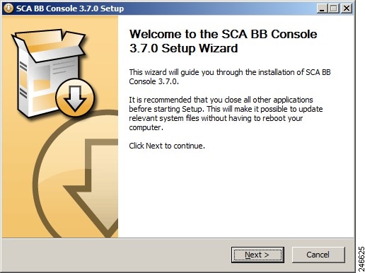
Step 2
How to Install the Cisco SCA BB Configuration Utilities
Installing the Cisco SCA BB configuration utilities is optional.
Step 1
Step 2
These files are in the bin directory:
–
–
–
Installing the Application and Protocol Pack on the Cisco SCE Platform
Use the Cisco SCE Software Upgrade wizard in the console to install the application file (PQI) and the protocol pack (SPQI) on selected Cisco SCE platforms.
Before You Start
Before you begin the Cisco SCE platform upgrade, ensure that you perform the following tasks:
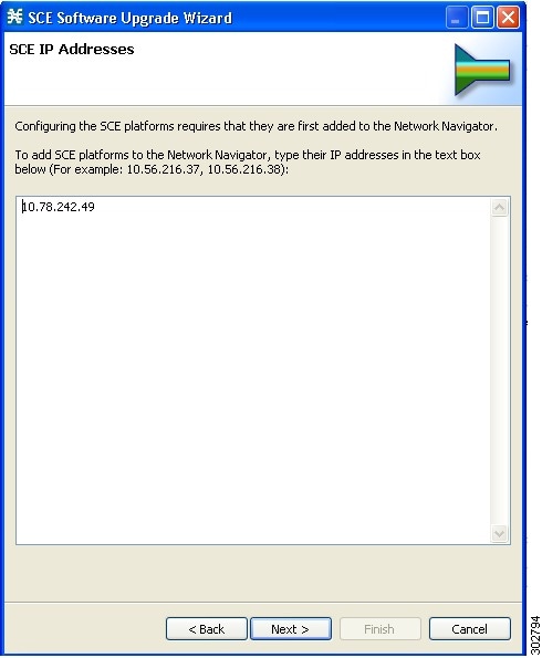
- If the IP addresses of the Cisco SCE platforms to be upgraded are not defined in the Network Navigator, gather the IP addresses of all SCE platforms to be upgraded.
- Download the relevant PQI file and protocol pack to a local location or to a location accessible by FTP. If using an FTP site, make sure you have the complete FTP location and path for each file.
How to Install Files on the Cisco SCE Platform
Step 1
If the Cisco SCE platforms are not yet defined in the Network Navigator, you can select the site node.
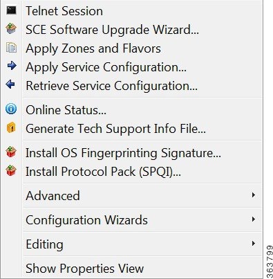
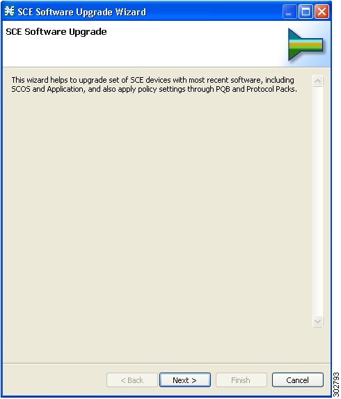
The SCE Software Upgrade Wizard opens. Click Next(see Figure 7) .
Figure 7 SCE Software Upgrade Wizard
Step 2
Figure 8 SCE Software Upgrade Wizard—SCE IP Addresses
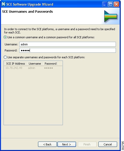
Step 3
Figure 9 SCE Software Upgrade Wizard—SCE Usernames and Passwords Window
Step 4
Figure 10 SCE Software Upgrade Wizard—SCE Firmware (PKG) Installation
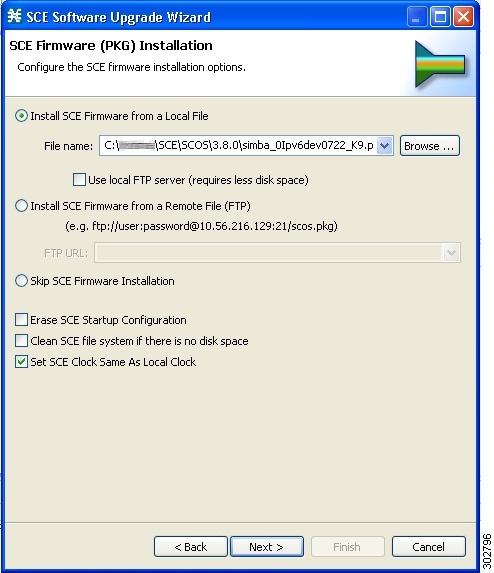
Step 5
Figure 11 SCE Software Upgrade Wizard—SCE Application Software (PQI) Installation
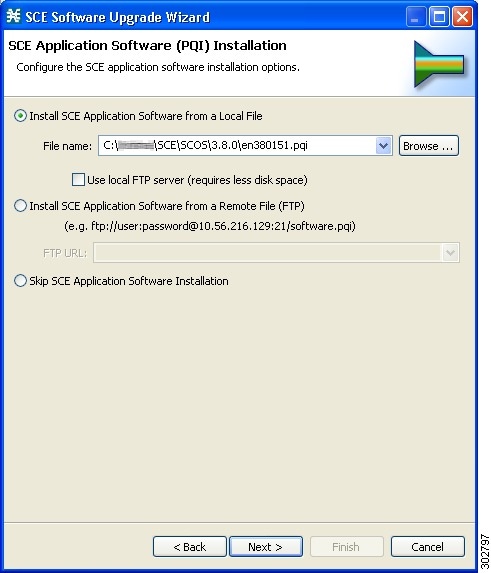
Step 6
Note If you install the protocol pack during the upgrade, it must be the same version or a later version of the protocol pack you are upgrading from.
Figure 12 SCE Software Upgrade Wizard—Protocol Pack (SPQI) Update
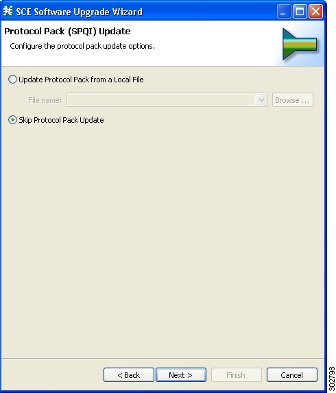
Note Cisco SCE does not support direct downgrade of higher PP versions to a lower PP version. While downgrading the protocol pack from a higher version to a lower version, the Cisco SCA BB console displays an error message and prevents you from applying the policy on the Cisco SCE.
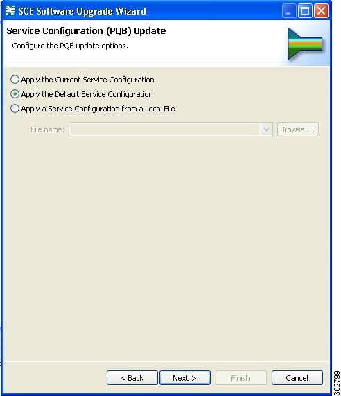
Step 7
Figure 13 SCE Software Upgrade Wizard—Service Configuration (PQB) Update
Step 8
Note If a connection to one or more devices cannot be made, or if there is a problem with the connection (such as invalid version of the device), an error is displayed next to the device. (You can skip these tests by clicking Skip connectivity test). The connections are validated when you click Finish.
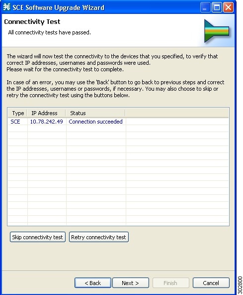
Step 9
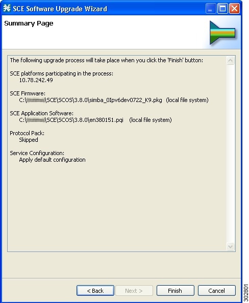
Figure 15 SCE Software Upgrade Wizard—Summary
Initial Configuration
This section describes the initial configuration of the system.
After all the Service Control components have been installed, perform these tasks to complete the initial setup and configuration of the system:
Step 1
Step 2
Step 3
Step 4
Step 5
Note
Initial Configuration of the Cisco SCE 10000 Platform
There are several basic global parameters that must be correctly configured for the Cisco SCE platform to communicate properly with the outside world. The following is a brief summary of the initial setup parameters and commands. For more information, see the Cisco SCE10000 Software Configuration Guide .
- Connect to the CIMC and launch the KVM Console to configure the management IP address.
- IP address of the default gateway.
- Hostname—The hostname is used to identify the Cisco SCE platform. It appears as part of the CLI prompt and is also returned as the value of the MIB-II object sysName.
–
–
- Passwords for user, admin, and root-level access. These are authorization-level passwords, not individual passwords. These passwords may be encrypted.
These passwords must meet the following criteria:
–
–
–
–
- The default password for all levels is cisco .
- System clock—Current date and time. The clock and the calendar must always be synchronized.
- Time zone—The name or ID of the time zone along with the number of hours offset from Coordinated Universal Time (UTC).
- Domain name server—The default domain name used to complete unqualified host names, as well as up to three domain name servers, that are used for DNS lookup. You must also enable DNS lookup.
- RDR formatter destination—The Cisco SCE platform generates RDRs and sends them to the specified destinations (external collection systems) via the RDR formatter. You can configure up to eight RDR formatter destinations. Specify the IP address and port number for each destination.
Table 5 lists the commands both for displaying the currently configured values and for configuring these parameters. It also lists the command mode for each configuration command. All the show commands are executed in the user EXEC command mode.
Initial Cisco SCA BB Configuration
Initial SCA BB configuration includes two main aspects:
- Defining your site—Defining all your Cisco Service Control components. Use the Usage Analysis wizard to define your site.
- Defining a basic service configuration.
Use this wizard to perform these tasks:
- Create the site.
- Create a service configuration called Usage Analysis with the following characteristics:
–
–
How to Use the Usage Analysis Wizard to Define the Default Site
The Usage Analysis wizard allows you to create a simple model of devices and connect to them.
Note
To use Usage Analysis Wizard to define the default site, complete these steps:
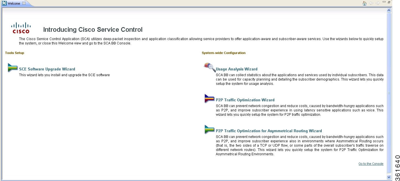
Step 1
The Welcome window opens (see Figure 16) .
Step 2
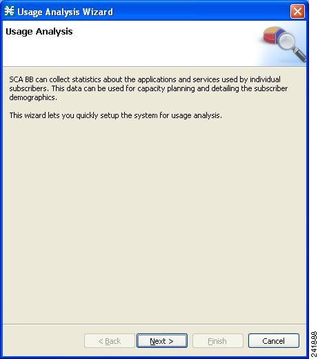
The Usage Analysis Wizard window appears (see Figure 17) .
Figure 17 Usage Analysis Wizard—Usage Analysis
The SCE IP Addresses window opens ( Figure 18 ).
Figure 18 Usage Analysis Wizard—SCE IP Addresses Window
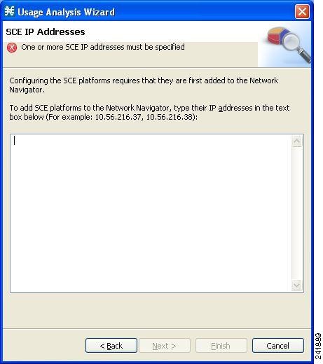
Step 4
Note You can work with up to 20 Cisco SCE devices simultaneously by using the wizard.
The SCE Usernames and Passwords window opens (see Figure 19 ).
Figure 19 Usage Analysis Wizard—SCE Usernames and Passwords Window
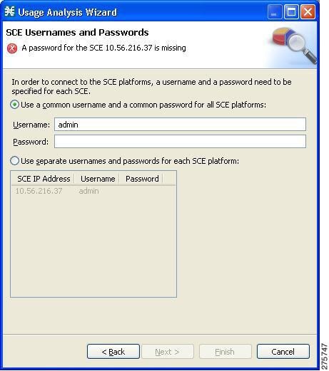
Step 6
- To use the same username and password for all the SCE devices that you are adding, enter the user name in the Username field and the password in the Password field.
- To provide a different user name and password pair for each SCE device, click the Use separate usernames and passwords for each SCE platform radio button, and, for each SCE device, enter the user name and password in the appropriate cell of the table.
The CM Setup window opens (see Figure 20 ).
Figure 20 Usage Analysis Wizard—CM Setup Window
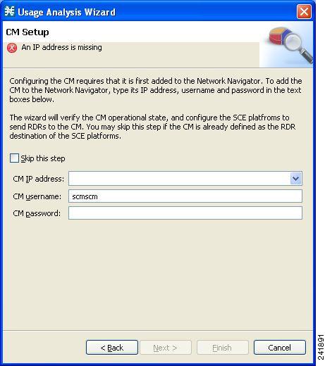
Step 8
If you started from the Network Navigator, this information is retrieved and displayed. You can modify these parameters.
The Connectivity Test window opens (see Figure 21 ).
Figure 21 Usage Analysis Wizard—Connectivity Test Window
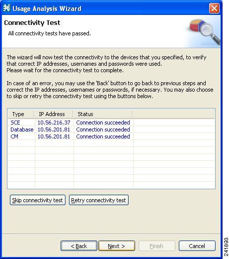
The wizard tests to see that the connections to the defined devices can be made.
Note If a connection to one or more of the devices cannot be made, or if there is some problem with the connection (such as invalid version of the device), an error is displayed next to the device. You can skip these tests by clicking Skip connectivity test. The connections are validated when you click Finish at the end of the wizard.
The Anonymous Subscribers window opens (see Figure 22 ).
Figure 22 Usage Analysis Wizard—Anonymous Subscribers Window
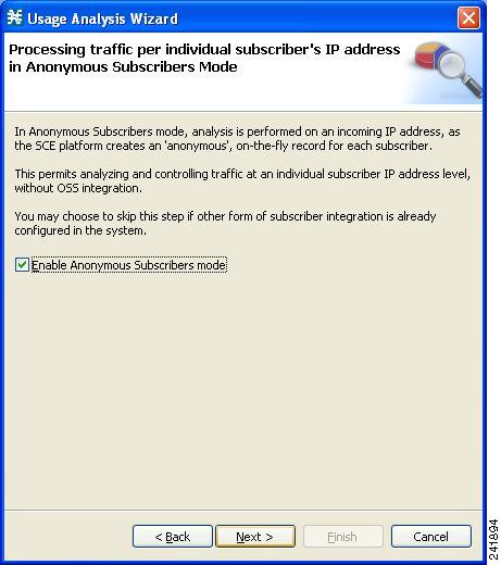
Step 11
The Confirmation window opens (see Figure 23 ).
Figure 23 Usage Analysis Wizard—Confirmation Window
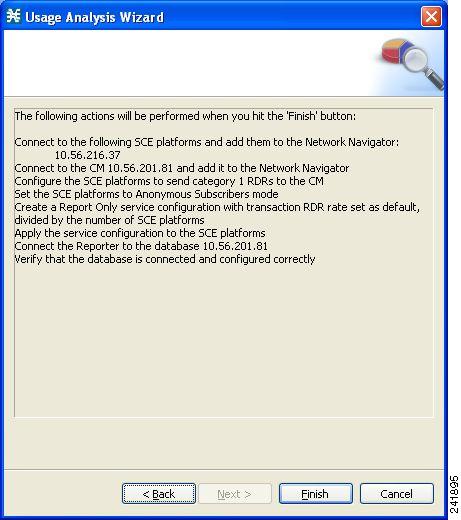
The actions that the wizard is about to take are listed on the page.
The Configuration Output window opens (see Figure 24 ).
Figure 24 Usage Analysis Wizard—Configuration Output Window
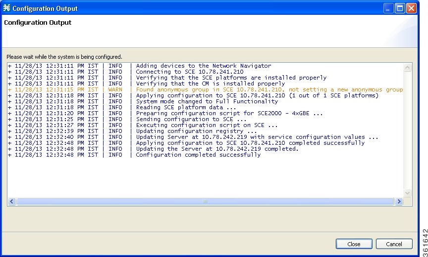
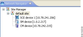
New devices are added to the default site of the Site Manager tree in the Network Navigator (see Figure 25) .
The wizard attempts to connect to all the devices that you defined. The operation fails if:
–
–
If you defined a Collection Manager in Step 8 , the SCE devices are configured so that the only category 1 RDR destination is the CM.
A new service configuration named Usage Analysis is created, and opens in the Service Configuration Editor (see Figure 26 ).
Figure 26 Service Configuration Editor
The service configuration has these characteristics:
- They are in Report Only mode.
- The maximum Transaction RDR rate is set as the default value (250) divided by the number of SCE devices. (To configure the Transaction RDR see How to Manage Transaction RDRs in the Cisco Service Control Application for Broadband User Guide . The content and structure of the Transaction RDR is listed in “Transaction RDR” in the “Raw Data Records: Formats and Field Contents” chapter of Cisco Service Control Application for Broadband Reference Guide .)
The service configuration is applied to the SCE devices.
The Usage Analysis wizard closes.
Configuring the Subscriber Manager
After installing the SCMS Subscriber Manager, you can configure the Subscriber Manager to your specific needs. In particular, address these parameters:
- topology—Cluster or standalone
- introduction_mode—Pull or push
- support_ip_ranges—Whether IP ranges should be used in the installed setup
To configure the Subscriber Manager, edit the p3sm.cfg configuration file by using any standard text editor. The configuration file is described in detail in the Configuration and Management module and in the Configuration File Options module of Cisco Service Control Management Suite Subscriber Manager User Guide .
After you finish editing the p3sm.cfg configuration file, use the p3sm utility to update the Subscriber Manager with the new settings:
At your workstation shell prompt, run the p3sm command.
This p3sm command loads the configuration file and updates the Subscriber Manager configuration accordingly:
System Requirements and Prerequisites
This chapter summarizes the system requirements and prerequisites of the Cisco SCE 10000 platform.
Overall System Requirements
- The SCE platform—Cisco SCE 10000 and CIMC connected to LAN.
- Cisco SCA BB—Workstation running Windows 2000, Windows XP, Windows Vista, or Windows 7.
- SCMS Subscriber Manager
–
The actual number of computers required depends on the number of subscribers in the system.
–
The actual number of computers required depends on the amount of traffic in the system.
Operating System Requirements
The Cisco SCA BB Console can run on Windows 2000, Windows XP, Windows Vista, or Windows 7.
Java Runtime Environment
If you are using the optional SCA BB Service Configuration Utility, servconf , it requires access to JRE version 1.6.
You can download a JRE from the Sun™ website at http://java.com/en/download/ .
To verify that the JRE is installed, run java-version at the command prompt. The Java version should start with 1.6.
If a different version of JRE is also installed on the workstation, you may need to tell servconf where to find the appropriate JRE. Do this configuration by setting the JAVA_HOME environment variable to point to the JRE 1.6 installation directory. For example:
Subscriber Manager System Requirements
You can install the SCMS Subscriber Manager on the following platforms:
- Intel machine (64-bit) running 64-bit versions of Red Hat Enterprise Linux 5.0 and later or Red Hat Enterprise Linux 6.0.
- Intel-based machine (64-bit) running 64-bit versions of CentOS with a 64-bit version of the Java Virtual Machine. See Table 6 and Table 7 .
- Cisco Unified Computing System (UCS) server model UCSC-C420-M3 with a Intel Xeon E5-4650 @ 2.70 GHz four processors, 32 cores.
The machine should conform to the system requirements listed in Table 6 and Table 7 .
Note
For the hardware and software system requirements for the Veritas Cluster Server, see the Veritas Cluster Server chapter of the Cisco Service Control Management Suite Subscriber Manager User Guide .
Note
Red Hat Enterprise Linux AS/ES 4.0/5.0; currently, both 32-bit and 64-bit versions are supported.
Note
Note
Cisco Service Control Collection Manager System Requirements
The Cisco Service Control Collection Manager and its database are software components that run on a server platform. They can be installed on any of these configurations:
- Intel machine running 64-bit versions of Red Hat Enterprise Linux 5.x or Red Hat Enterprise Linux 6.x. (See the “Red Hat Linux Requirements” section )
All configurations use a 32-bit Java Virtual Machine (JVM).
Note
These sections describe the Collection Manager system requirements:
Checking a System’s Prerequisites
The CM distribution contains a script, check_prerequisites.sh, located in the install_scripts directory:
check_prerequisites.sh [ --sybhome = SYBHOME ] [ --cmhome = CMHOME ] [ --datadir = DATADIR ]
The script helps to determine if a system meets the requirements for installing a CM or the bundled Sybase database. It also checks the overall readiness of the system for a Collection Manager or Sybase installation. The main prerequisites that are checked are:
- CPU speed
- Amount of RAM
- OS version (Red Hat Enterprise Linux 5 or 6)
- Additional required and optional packages
- Python installed and executable in path
- Free space for CM
- Names for all the network interface cards (NICs)
- Locale and time zone formats
Table 8 describes the options available in the check_prerequisites.sh script.
Note
Red Hat Linux Requirements
Collection Manager Version 5.0.x or later can be installed on any x64 running Red Hat Linux that conforms to the requirements listed in these sections:
The hardware requirements are:
–
The software and environment requirements are:
–
–
- Red Hat Enterprise Base Installation.
- Apply the latest recommended patches from Red Hat.
- Reserve at least 8 GB free on the partition where the Collection Manager is to be installed. (This is used for CSV storage and persistent buffers.)
- If you are using database periodic delete, the scmscm user should be able to schedule and run cron jobs.
Obtaining Documentation and Submitting a Service Request
For information on obtaining documentation, submitting a service request, and gathering additional information, see the monthly What’s New in Cisco Product Documentation , which also lists all new and revised Cisco technical documentation, at:
http://www.cisco.com/en/US/docs/general/whatsnew/whatsnew.html
Subscribe to the What’s New in Cisco Product Documentation as a Really Simple Syndication (RSS) feed and set content to be delivered directly to your desktop using a reader application. The RSS feeds are a free service and Cisco currently supports RSS Version 2.0.
Cisco and the Cisco logo are trademarks or registered trademarks of Cisco and/or its affiliates in the U.S. and other countries. To view a list of Cisco trademarks, go to this URL: www.cisco.com/go/trademarks . Third-party trademarks mentioned are the property of their respective owners. The use of the word partner does not imply a partnership relationship between Cisco and any other company. (1110R)
 Feedback