- Preface
- Chapter 1-Basic Troubleshooting Tasks and Startup Issues
- Chapter 2-PEM Faults and Fan Assembly Failures
- Chapter 3-Troubleshooting PRE Modules
- Chapter 4-Troubleshooting Line Cards and Interface Modules
- Chapter 5-Replacing or Recovering Passwords
- Appendix A Recommended Tools and Test Equipment
Cisco uBR10012 Universal Broadband Router Hardware Troubleshooting Guide for Cisco IOS Release 12.2SC
Bias-Free Language
The documentation set for this product strives to use bias-free language. For the purposes of this documentation set, bias-free is defined as language that does not imply discrimination based on age, disability, gender, racial identity, ethnic identity, sexual orientation, socioeconomic status, and intersectionality. Exceptions may be present in the documentation due to language that is hardcoded in the user interfaces of the product software, language used based on RFP documentation, or language that is used by a referenced third-party product. Learn more about how Cisco is using Inclusive Language.
- Updated:
- March 18, 2015
Chapter: Chapter 1-Basic Troubleshooting Tasks and Startup Issues
Basic Troubleshooting Tasks and Startup Issues
This section describes the basic procedures that users should perform before undertaking a detailed troubleshooting analysis of the Cisco uBR10012 router or logging a case with the Cisco Technical Assistance Center (TAC).
These basic troubleshooting checks are organized as follows:
•![]() Basic Troubleshooting Checklist
Basic Troubleshooting Checklist
•![]() Displaying the Cisco IOS Software Version
Displaying the Cisco IOS Software Version
•![]() Displaying System Environment Information
Displaying System Environment Information
•![]() Hardware Troubleshooting Flowchart
Hardware Troubleshooting Flowchart
•![]() Cisco uBR10012 System Startup Sequence
Cisco uBR10012 System Startup Sequence
Basic Troubleshooting Checklist
If you encounter a problem after you install the Cisco uBR10012 router, go through the following troubleshooting checklist to check for the most common error conditions before you contact the Cisco Technical Assistance Center (TAC) or before you perform a detailed troubleshooting analysis:
1. ![]() Is the power on?
Is the power on?
2. ![]() Is each Power Entry Module (PEM) securely inserted into the router? Is each PEM connected to a power source that is supplying voltage in the proper AC or DC range? Are all power leads and cables firmly connected at both ends?
Is each Power Entry Module (PEM) securely inserted into the router? Is each PEM connected to a power source that is supplying voltage in the proper AC or DC range? Are all power leads and cables firmly connected at both ends?
3. ![]() Is the fan assembly module installed in the chassis and operating? Can you hear the fans operating, and when you put your hand in front of the fan blowers, can you feel the air flow? Are all empty slots covered with blank front panels, to ensure the correct air flow through the chassis for cooling?
Is the fan assembly module installed in the chassis and operating? Can you hear the fans operating, and when you put your hand in front of the fan blowers, can you feel the air flow? Are all empty slots covered with blank front panels, to ensure the correct air flow through the chassis for cooling?
4. ![]() Is each Performance Routing Engine (PRE) module firmly seated and securely inserted in the chassis?
Is each Performance Routing Engine (PRE) module firmly seated and securely inserted in the chassis?
5. ![]() Is at least one Timing, Communication and Control Plus (TCC+) card installed in the router?
Is at least one Timing, Communication and Control Plus (TCC+) card installed in the router?
6. ![]() Are the other line cards firmly seated and securely screwed to the chassis?
Are the other line cards firmly seated and securely screwed to the chassis?
7. ![]() Are all data cables firmly connected at both ends?
Are all data cables firmly connected at both ends?
8. ![]() Are the ports properly configured?
Are the ports properly configured?
After going through this checklist, go through the remaining sections in this chapter to verify the installation and to perform basic troubleshooting.
Displaying the Cisco IOS Software Version
Use the show version command to confirm that the router is running the proper version of Cisco IOS software and has a sufficient amount of system memory. The command also reports the system uptime and the method by which the system was powered up.
In the following sample of output from the show version command, some of the information that may be useful for troubleshooting appears in bold type:
Router#show ver
Cisco IOS Software, 10000 Software (UBR10K4-K9P6U2-M), Version 12.2(32.8.12)SCE
Copyright (c) 1986-2010 by Cisco Systems, Inc.
Compiled Sun 21-Nov-10 15:58 by jdkerr
ROM: System Bootstrap, Version 12.2(20071113:194412) [shalpin-rom-1_2 101], DEVELOPMENT
SOFTWARE
Router uptime is 5 hours, 13 minutes
Uptime for this control processor is 5 hours, 14 minutes
System returned to ROM by reload at 01:27:43 UTC Thu Nov 25 2010
System restarted at 20:29:12 SGT Wed Nov 24 2010
System image file is "disk0:ubr10k4-k9p6u2-mz.122-32.8.12.SCE"
Last reload type: Normal Reload
Last reload reason: Reload command
This product contains cryptographic features and is subject to United States and local
country laws governing import, export, transfer and use. Delivery of Cisco cryptographic
products does not imply third-party authority to import, export, distribute or use
encryption.Importers, exporters, distributors and users are responsible for compliance
with U.S. and local country laws. By using this product you agree to comply with
applicable laws and regulations. If you are unable to comply with U.S. and local laws,
return this product immediately.
A summary of U.S. laws governing Cisco cryptographic products may be found at:
http://www.cisco.com/wwl/export/crypto/tool/stqrg.html
If you require further assistance please contact us by sending email to export@cisco.com.
Cisco uBR10000 (PRE4-RP) processor with 2588671K/163839K bytes of memory.
Processor board ID SPE10310CUH
SB-1 CPU at 800Mhz, Implementation 0x410, Rev 5.0, 512KB L2 Cache
Backplane version 1.1, 8 slot
Last reset from software reset
PXF processor tmc0 is running.
PXF processor tmc1 is running.
PXF processor tmc2 is running.
PXF processor tmc3 is running.
1 DTCC card(s)
1 Jacket card(s): 3 SPA card(s)
1 FastEthernet interface
6 Gigabit Ethernet interfaces
1 Ten Gigabit Ethernet interface
15 Cable Modem interfaces
7039K bytes of non-volatile configuration memory.
125440K bytes of ATA compact flash in bootflash (Sector size 512 bytes).
500472K bytes of ATA compact flash in disk0 (Sector size 512 bytes).
Standby is up
Standby has 2752512K bytes of memory
Configuration register is 0x2
Router#
Displaying System Environment Information
Use the show environment command to display the basic system environment status, to verify the following:
•![]() Make sure that the system operating temperature is always between 41
Make sure that the system operating temperature is always between 41
degrees F or 5
degrees
C at the inlet and 104
degrees F or 40
degrees C at the core.
•![]() That the fan assembly module is installed in the chassis and operating properly.
That the fan assembly module is installed in the chassis and operating properly.
•![]() Report that the operational status of the PEMs and blower is OK.
Report that the operational status of the PEMs and blower is OK.
If the operating temperature is not between 41
degrees F or 5
degrees C and 104
degrees F or 40
degrees
C, refer to the
"Fan Assembly Module Faults" section on page 2-6.
The following example is sample output from the show environment command for a system with PRE4 and two DC PEMs and installed:
Router# show environment
Load for five secs: 0%/0%; one minute: 0%; five minutes: 0%
Time source is hardware calendar, *02:43:21.219 EDT Mon May 31 2010
Temperature information:
Temperature normal: Inlet sensor measured at 33C/91F
Temperature normal: Outlet sensor measured at 46C/114F
Voltage information:
RP Voltage readings :
Channel Margin ADC Value
======================================
2.5v Normal 2.49v
1.8v N/A 1.80v
1.5v Normal 1.49v
1.8vFPGA Normal 1.79v
1.2v Normal 1.19v
3.3v Normal 3.28v
Fan: OK
Power Entry Module 0 type DC status: OK
Power Entry Module 1 type DC status: Output Disabled
The following example is sample output from the show environment command for a system with PRE2 and two DC PEMs and installed:
Router# show environment
Temperature normal: chassis inlet measured at 34C/93F
Fan: OK
Power Entry Module 0 type DC status: OK
Power Entry Module 0 Power: 432w
Power Entry Module 0 Voltage: 54v
Power Entry Module 1 type DC status: OK
Power Entry Module 1 Power: 486w
Power Entry Module 1 Voltage: 54v
Router#
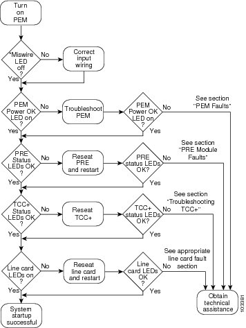
Hardware Troubleshooting Flowchart
Use Figure 1-1 to determine which component of your Cisco uBR10012 router is malfunctioning. Figure 1-1 describes a series of hardware dependent startup events that must take place for a Cisco uBR10012 router to allow the passage of IP traffic. At each main point of the flowchart, there are pointers to the chapters in this guide that describe how to troubleshoot individual pieces of hardware.

Note ![]() This flowchart does not address software configuration problems.
This flowchart does not address software configuration problems.
Figure 1-1 Hardware Troubleshooting Flowchart
Cisco uBR10012 System Startup Sequence
Table 1-1 describes the visible sequence of events that occur during a typical Cisco uBR10012 power up.
 Feedback