Maintaining the Supervisor in the Cisco cBR Chassis
 Note |
Any time a physical Online Insertion/Removal (OIR) is performed, the removed module must be left out 30-60 seconds before re-inserting it in the cBR-8 chassis. |
Maintaining the Supervisor 160G
Removing the Supervisor Card from the Cisco cBR Chassis
Perform this procedure to remove the following cards:
-
Supervisor Card
-
Blank card for the Supervisor
Before you begin
 Caution |
|
-
Attach an ESD-preventive wrist strap to your wrist and connect the other end to the grounding lug connected to the chassis.
-
Disconnect all the cables and memory stick or flash drives from the Supervisor Card.
-
Close the tethered I/O door by pushing the door until it snaps into place on the spring-loaded ejector of the Supervisor Card.
Figure 1. Closing the Tethered I/O Door on the Supervisor Card 1
Tethered I/O door
—
-
Be aware of the weight and size of the equipment. Handle it with care.
-
Ensure that a replacement Supervisor Card or a blank card is readily available to replace the removed Supervisor Card or blank card in an operational chassis.
Caution
After removing the Supervisor Card or blank card from an operational chassis, install the replacement Supervisor Card or blank card in the chassis within 3 minutes to prevent the chassis from shutting down due to possible overheating of some components.
Required Tools and Equipment
-
ESD-preventive wrist strap
-
3/16" flat-blade screwdriver
-
Antistatic bag
Procedure
| Step 1 |
Loosen the captive screws on the card using a 3/16" flat-blade torque screwdriver until the red bands are visible on the captive screws. |
||
| Step 2 |
Pull the spring-loaded ejectors on the card until they release and are perpendicular to the faceplate. This disengages the card from the chassis. |
||
| Step 3 |
Carefully slide the card out of its slot applying even pressure using both your hands. |
||
| Step 4 |
Grasp the faceplate of the card with one hand and place your other hand under the card to support its weight, and remove the card from its slot. |
||
| Step 5 |
Place the removed Supervisor Card in an antistatic bag.
|
What to do next
Removing the SFP+ Module from the Supervisor PIC
Before you begin
Caution |
Do not install or remove the SFP+ module with fiber-optic cables still attached to it. Doing so may damage cables, cable connectors, or the optical interfaces and may interfere with the SFP+ module latching properly into its socket connector. Disconnect all cables before removing or installing an SFP transceiver module. |
-
Attach an ESD-preventive wrist strap to your wrist and connect the other end to the grounding lug connected to the chassis.
-
Removing and installing an SFP+ module can shorten its useful life. Do not remove and insert SFP+ modules more often than is absolutely necessary.
Required Tools and Equipment
-
ESD-preventive wrist strap
-
Dust plugs for the SFP+ module
-
Antistatic bag
Procedure
| Step 1 |
Disconnect the fiber-optic cable from the SFP+ port for removing the SFP+ module from the Supervisor PIC. Immediately reinstall the dust plug in the optical bores and the fiber-optic cable LC connectors .
|
||
| Step 2 |
Release the bail clasp on the SFP+ module, by pushing the small tab up and outwards with your index finger to release the bail clasp. 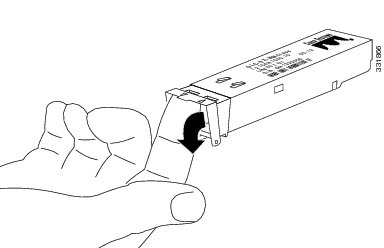 |
||
| Step 3 |
Grasp the SFP+ module between your thumb and index finger and carefully remove it from the socket. |
||
| Step 4 |
Place the removed SFP+ module in an antistatic bag. |
What to do next
Replace the SFP+ module (if required).
Removing the Supervisor PIC Cable Management Bracket
The Supervisor PIC cable management bracket is usually removed when the Supervisor PIC needs to be replaced.
Before you begin
-
Attach an ESD-preventive wrist strap to your wrist and connect the other end to the grounding lug connected to the chassis.
-
Remove all the cables that are routed through the Supervisor PIC cable management bracket.
Required Tools and Equipment
-
ESD-preventive wrist strap
-
3/16" flat-blade screwdriver
Procedure
| Step 1 |
Loosen the two captive screws that secure the Supervisor PIC cable management bracket using a 3/16" flat-blade screwdriver.
|
||||
| Step 2 |
Remove the Supervisor PIC cable management bracket. |
What to do next
Replace the cable management bracket (if required).
Removing the Supervisor PIC from the Cisco cBR Chassis
Perform this procedure to remove the following PIC:
-
Supervisor PIC
-
Blank PIC for the Supervisor
Before you begin
Caution |
|
-
Attach an ESD-preventive wrist strap to your wrist and connect the other end to the grounding lug connected to the chassis.
-
Disconnect all the cables from the Supervisor PIC.
-
Be aware of the weight and size of the equipment. Handle it with care.
-
Ensure that a replacement Supervisor PIC or a blank PIC is readily available to replace the removed Supervisor PIC or blank PIC in an operational chassis.
Caution
After removing the Supervisor PIC or blank PIC from an operational chassis, install the replacement Supervisor PIC or blank PIC in the chassis within 3 minutes to prevent the chassis from shutting down due to possible overheating of some components.
Restrictions
-
The Supervisor Card does not power up if the Supervisor PIC is not present during powering up of the chassis.
Required Tools and Equipment
-
ESD-preventive wrist strap
-
3/16" flat-blade screwdriver
-
Antistatic bag
Procedure
| Step 1 |
Loosen the four captive screws on the PIC using a 3/16" flat-blade screwdriver. |
||
| Step 2 |
Pull the ejector levers on the PIC to disengage the midplane connectors. |
||
| Step 3 |
Carefully slide the PIC out of the slot applying even pressure using both your hands. |
||
| Step 4 |
Place the removed Supervisor PIC in an antistatic bag.
|
What to do next
Maintaining the Supervisor 250G
Removing the Supervisor Card from the Cisco cBR Chassis
Perform this procedure to remove the following cards:
-
Supervisor Card
-
Blank card for the Supervisor
Before you begin
Caution |
|
-
Attach an ESD-preventive wrist strap to your wrist and connect the other end to the grounding lug connected to the chassis.
-
Disconnect all the cables and memory stick or flash drives from the Supervisor Card.
-
Close the tethered I/O door by pushing the door until it snaps into place on the spring-loaded ejector of the Supervisor Card.
Figure 9. Closing the Tethered I/O Door on the Supervisor Card 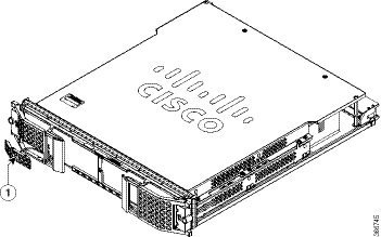
1
Tethered I/O door
—
-
Be aware of the weight and size of the equipment. Handle it with care.
-
Ensure that a replacement Supervisor Card or a blank card is readily available to replace the removed Supervisor Card or blank card in an operational chassis.
Caution
After removing the Supervisor Card or blank card from an operational chassis, install the replacement Supervisor Card or blank card in the chassis within 3 minutes to prevent the chassis from shutting down due to possible overheating of some components.
Required Tools and Equipment
-
ESD-preventive wrist strap
-
3/16" flat-blade screwdriver
-
Antistatic bag
Procedure
| Step 1 |
Loosen the captive screws on the card using a 3/16" flat-blade torque screwdriver until the red bands are visible on the captive screws. 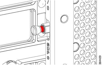 |
||
| Step 2 |
Pull the spring-loaded ejectors on the card until they release and are perpendicular to the faceplate. This disengages the card from the chassis. 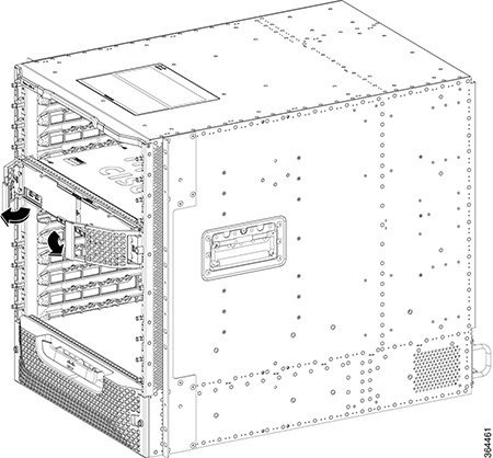 |
||
| Step 3 |
Carefully slide the card out of its slot applying even pressure using both your hands. 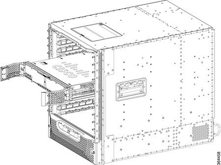 |
||
| Step 4 |
Grasp the faceplate of the card with one hand and place your other hand under the card to support its weight, and remove the card from its slot. |
||
| Step 5 |
Place the removed Supervisor Card in an antistatic bag.
|
What to do next
Removing the QSFP+ or QSFP28 Transceiver Module from the Supervisor PIC
Before you begin
Caution |
Do not install or remove the QSFP28 module with fiber-optic cables still attached to it. Doing so may damage cables, cable connectors, or the optical interfaces and may interfere with the QSFP28 module latching properly into its socket connector. Disconnect all cables before removing or installing an QSFP28 module. |
Caution |
The QSFP+ or QSFP28 transceiver module is a static-sensitive device. Always use an ESD wrist strap or similar individual grounding device when handling QSFP+ or QSFP28 transceiver modules or coming into contact with modules. |
Attach an ESD-preventive wrist strap to your wrist and connect the other end to the grounding lug connected to the chassis.
Required Tools and Equipment
-
Wrist strap or other personal grounding device to prevent ESD occurrences.
-
Antistatic mat or antistatic foam to set the transceiver on.
-
Fiber-optic end-face cleaning tools and inspection equipment.
Procedure
| Step 1 |
For optical QSFP+ or QSFP28 transceiver modules, disconnect the network interface cable from the QSFP+ or QSFP28 transceiver connector. |
| Step 2 |
For QSFP+ or QSFP28 transceiver modules equipped with a bail-clasp latch (see the below figure, top view):
|
| Step 3 |
For QSFP+ or QSFP28 transceivers equipped with a pull tab latch (see the below figure, bottom view):
|
| Step 4 |
Place the QSFP+ or QSFP28 transceiver module into an antistatic bag. |
What to do next
Replace the QSFP+ or QSFP28 module (if required).
Removing the Supervisor PIC Cable Management Bracket
The Supervisor PIC cable management bracket is usually removed when the Supervisor PIC needs to be replaced.
Before you begin
-
Attach an ESD-preventive wrist strap to your wrist and connect the other end to the grounding lug connected to the chassis.
-
Remove all the cables that are routed through the Supervisor PIC cable management bracket.
Required Tools and Equipment
-
ESD-preventive wrist strap
-
3/16" flat-blade screwdriver
Procedure
| Step 1 |
Loosen the two captive screws that secure the Supervisor PIC cable management bracket using a 3/16" flat-blade screwdriver. 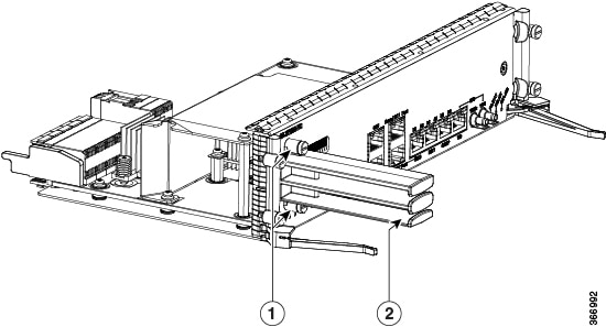
|
||||
| Step 2 |
Remove the Supervisor PIC cable management bracket. |
What to do next
Replace the cable management bracket (if required).
Removing the Supervisor PIC from the Cisco cBR Chassis
Perform this procedure to remove the following PIC:
-
Supervisor PIC
-
Blank PIC for the Supervisor
Before you begin
Caution |
|
-
Attach an ESD-preventive wrist strap to your wrist and connect the other end to the grounding lug connected to the chassis.
-
Disconnect all the cables from the Supervisor PIC.
-
Be aware of the weight and size of the equipment. Handle it with care.
-
Ensure that a replacement Supervisor PIC or a blank PIC is readily available to replace the removed Supervisor PIC or blank PIC in an operational chassis.
Caution
After removing the Supervisor PIC or blank PIC from an operational chassis, install the replacement Supervisor PIC or blank PIC in the chassis within 3 minutes to prevent the chassis from shutting down due to possible overheating of some components.
Restrictions
-
The Supervisor Card does not power up if the Supervisor PIC is not present during powering up of the chassis.
Required Tools and Equipment
-
ESD-preventive wrist strap
-
3/16" flat-blade screwdriver
-
Antistatic bag
Procedure
| Step 1 |
Loosen the four captive screws on the PIC using a 3/16" flat-blade screwdriver. |
||
| Step 2 |
Pull the ejector levers on the PIC to disengage the midplane connectors. 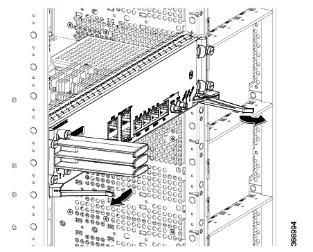 |
||
| Step 3 |
Carefully slide the PIC out of the slot applying even pressure using both your hands. |
||
| Step 4 |
Place the removed Supervisor PIC in an antistatic bag.
|
 Feedback