Cisco Vision Network, Server, and Video Headend Requirements Guide
Bias-Free Language
The documentation set for this product strives to use bias-free language. For the purposes of this documentation set, bias-free is defined as language that does not imply discrimination based on age, disability, gender, racial identity, ethnic identity, sexual orientation, socioeconomic status, and intersectionality. Exceptions may be present in the documentation due to language that is hardcoded in the user interfaces of the product software, language used based on RFP documentation, or language that is used by a referenced third-party product. Learn more about how Cisco is using Inclusive Language.
- Updated:
- May 19, 2020
Chapter: Cisco Vision Dynamic Signage Solution Component Overview
Cisco Vision Dynamic Signage Solution Component Overview
This section provides a brief overview of the components and operation of the Cisco Vision Dynamic Signage Solution.
The Cisco Vision Dynamic Signage Solution enables the integration and automated delivery of customized and dynamic content from multiple sources to different areas of the venue in standard definition (SD), high definition (HD), to ultra high definition (UHD). The solution is designed to enhance the visitor experience and provide the venue with additional revenue streams through targeted advertising via engaging, moving, dynamically updating content.
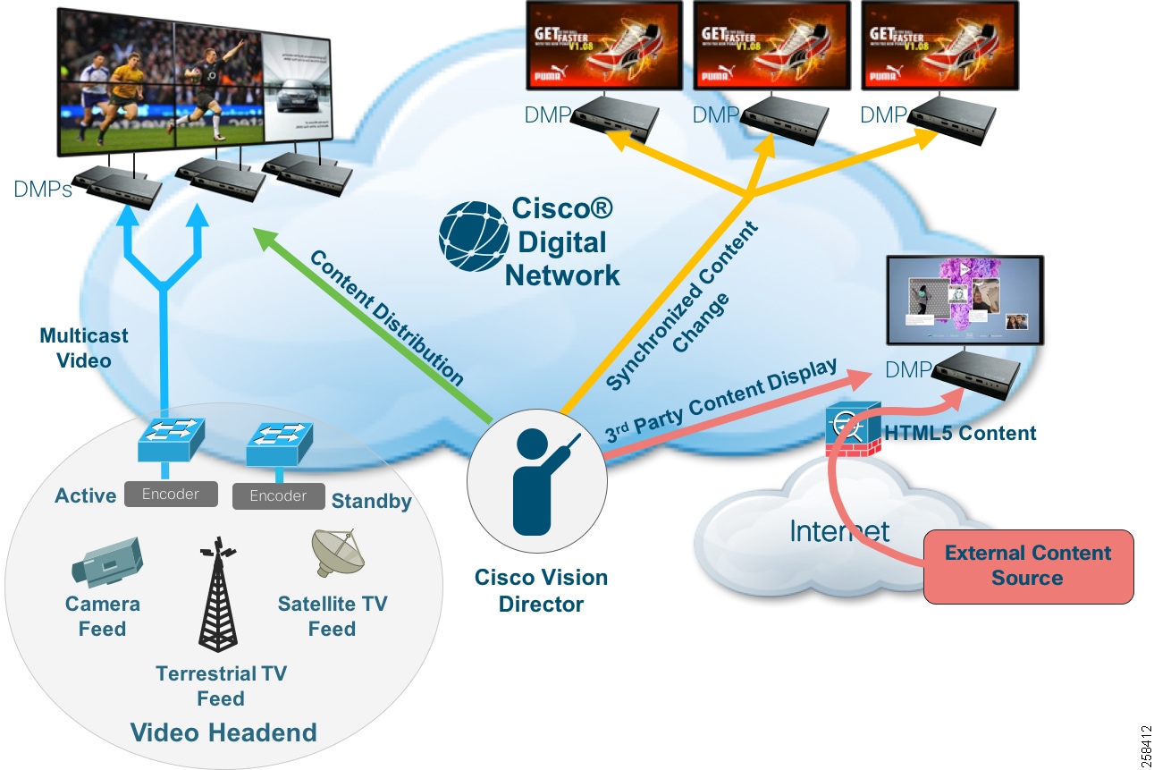
Four major components that constitute a Cisco Vision Dynamic Signage Solution (Figure 1):
■![]() Cisco Vision Dynamic Signage Director for centralized content management and operations
Cisco Vision Dynamic Signage Director for centralized content management and operations
■![]() Digital Media Player for content playback
Digital Media Player for content playback
■![]() Cisco Digital Network, the IP infrastructure foundation for content transport
Cisco Digital Network, the IP infrastructure foundation for content transport
■![]() Video Headend for video aggregation and distribution
Video Headend for video aggregation and distribution
Figure 1 Cisco Vision Dynamic Signage Solution Components
Cisco Vision Dynamic Signage Director
The Cisco Vision Dynamic Signage Director provides centralized management and operations for the Cisco Vision Dynamic Signage Solution. It acts as a single point of control for managing all Digital Media Player (DMP) endpoints, for placing and delivering content (video, graphics, and external content), for defining unique display areas (zones and groups), as well as for the creation of entitlement areas (bars, restaurants, clubs, and suites). It also provides the interface to third-party applications and devices, scoreboards and statistics systems, external contact closure and IP triggering systems, and third-party touch panels (for local, display control).
The capability requirements of the virtual server handling the Cisco Vision Dynamic Signage Director are based on the size and complexity of the deployment. There are two design size classifications defined in this document, primarily categorized by number of DMPs in the deployment: Standard and Small. However, other operational factors should also be taken into account.
|
|
|
|
|
|
|
|
1. Refer to Release 6.2: Cisco Vision Dynamic Signage Director Operations Guide.
For detailed server specifications refer to Cisco Vision Dynamic Signage Director Solution Requirements.
Sample Bill of Materials (BOM) for servers fitting various deployment scales of Cisco Vision Dynamic Signage Director are located in Appendix B: Bill of Material of this document.
Digital Media Player (DMP)
The DMP renders and displays static and dynamic content on each of the venue's connected displays. In addition to the support of UHD video resolution, the DMP can be powered by 802.3at Power over Ethernet (PoE) and supports dual video regions, video wall and virtual ribbon-board synchronization, and the rendering of HTML5 content. The DMP also supports Live TV playback via the HDMI 2.0a input to play content from any broadcast channel - even protected HDCP content.
For solution DMP deployment components, see Cisco Vision Product Deployment Requirements.
Cisco Digital Network
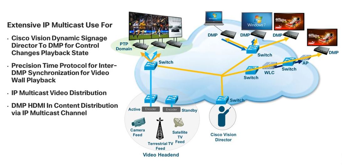
Cisco Digital Network is the foundational IP infrastructure that not only connects the video headend with the DMPs but typically interconnects all building IP endpoints to each other and to the outside world. The Cisco Vision Dynamic Signage Solution requires a converged, highly scalable, secure digital network designed specifically for low latency and redundancy to bring together all forms of access, communications, entertainment, and operations. This infrastructure is designed to enable the delivery of high-quality video, using advanced features of IP multicast and quality of service (QOS). This network also acts as the foundation to enable other services within the venue such as wireless communications, physical security, IP telephony, and network audio. The Cisco Digital Network is depicted in Figure 2.
Non-Cisco network deployment is possible if all documented requirements are satisfied. See Cisco Vision Dynamic Signage Solution Operation and Network Requirements guide.
Figure 2 Cisco Digital Network
Video Headend
The headend is where video is received from various sources such as in-house feeds (through the venue video control room), over-the-air channels (typically from local over-the-air broadcast networks), and broadcast channels from cable or satellite providers. It is responsible for placing the video feeds onto the IP network with minimal latency. Video feeds may be provided in Ultra HD or HD resolution and are in encrypted or unencrypted formats.
The headend of the Cisco Vision Dynamic Signage Solution is designed to accommodate all of these feeds and perform the necessary encoding, transcoding, and extracting to create H.264 (MPEG-4, Part 10), H.265 (HEVC), or legacy H.262 (MPEG-2) encoded streams. The headend then takes the processed streams, assigns a unique IP multicast address to each, and places it on the IP network to be joined by the DMP endpoints as a channel.
Figure 3 Video Headend Overview

Deployment Models
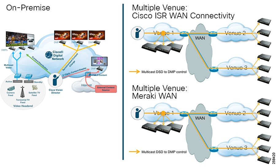
On-Premise
The on-premise deployment model resembles an Enterprise client-server model with a server and its associated endpoints connected to an Enterprise campus network. The Cisco Vision Dynamic Signage Director server typically resides in the Data Center or in a Video Distribution service block (i.e., Video Headend) usually located near the broadcast room where all the various video input source feeds enter the venue.
Multiple Venue
The multiple venue deployment model is one where the Dynamic Signage Director is located at a central location and DMPs are distributed locally and across a WAN to remote locations. The WANs supported here include Cisco ISR (Integrated Services Router) which supports multicast, or Meraki-based WAN (unicast support only).
Figure 4 Deployment Model Overview
 Feedback