- Cisco StadiumVision Director External Content Integration Guide, Release 3.0
- Preface
- Overview of External Content Integration in Cisco StadiumVision Director
- Configuring External Content Integration in Cisco StadiumVision Director
- Configuring Optional and Advanced Tasks for External Content Integration
- Designing the Layout of External Content Using the Widgets Tool
- Troubleshooting External Content Integration in Cisco StadiumVision Director
Release 3.0: Cisco StadiumVision Director External Content Integration Guide
Bias-Free Language
The documentation set for this product strives to use bias-free language. For the purposes of this documentation set, bias-free is defined as language that does not imply discrimination based on age, disability, gender, racial identity, ethnic identity, sexual orientation, socioeconomic status, and intersectionality. Exceptions may be present in the documentation due to language that is hardcoded in the user interfaces of the product software, language used based on RFP documentation, or language that is used by a referenced third-party product. Learn more about how Cisco is using Inclusive Language.
- Updated:
- August 1, 2012
Chapter: Configuring External Content Integration in Cisco StadiumVision Director
- Before You Begin
- Workflow Summary for External Content Integration
- How to Configure External Content Integration
- Accessing the External Content Integration Interface
- Configuring the Network Connection to the External Content Source
- Configuring Data Throttling
- Enabling the Data Source Configuration
- Activating External Content Integration System-Wide From the Management Dashboard
- Restarting the External Content Integration Application
- Selecting Input Statistics and Mapping to Output Fields for Display
- Verifying the Integration
Configuring External Content Integration in Cisco StadiumVision Director
This module describes the requirements and how to configure support for external data sources in Cisco StadiumVision Director.
This module includes the following topics:
•![]() Workflow Summary for External Content Integration
Workflow Summary for External Content Integration
•![]() How to Configure External Content Integration
How to Configure External Content Integration
Before You Begin
Before you configure Cisco StadiumVision Director for External Content Integration, be sure that the following requirements are met for the system that you are integrating with:
•![]() Prerequisites for Configuring NFL GSIS Integration
Prerequisites for Configuring NFL GSIS Integration
•![]() Prerequisites for Configuring OES ISC9000 Scoreboard Integration
Prerequisites for Configuring OES ISC9000 Scoreboard Integration
•![]() Prerequisites for Configuring Daktronics All Sport 5000 Scoreboard Integration
Prerequisites for Configuring Daktronics All Sport 5000 Scoreboard Integration
Prerequisites for Configuring NFL GSIS Integration
Before you configure the National Football League (NFL) Game Statistics and Information System (GSIS) integration, be sure that the following requirements are met:
•![]() The required Cisco StadiumVision Director server hardware is installed and running Cisco StadiumVision Release 3.0 or later.
The required Cisco StadiumVision Director server hardware is installed and running Cisco StadiumVision Release 3.0 or later.
•![]() The NFL Stats-in-a-Box (SIAB) server is installed at the venue and is connected to the NFL GSIS database. Advise your network administrator to allow communication between these two servers.
The NFL Stats-in-a-Box (SIAB) server is installed at the venue and is connected to the NFL GSIS database. Advise your network administrator to allow communication between these two servers.
•![]() The SIAB server is reachable by the Cisco StadiumVision Director server on the Internet Protocol (IP) network.
The SIAB server is reachable by the Cisco StadiumVision Director server on the Internet Protocol (IP) network.
•![]() For support of the NFL GSIS clock, a router in the network must be configured for Network Address Translation (NAT) to change the local broadcast address to the unicast IP address of the Cisco StadiumVision Director server.
For support of the NFL GSIS clock, a router in the network must be configured for Network Address Translation (NAT) to change the local broadcast address to the unicast IP address of the Cisco StadiumVision Director server.

Tip ![]() You can verify reachability using the ping command from the Cisco StadiumVision Director server to the SIAB server.
You can verify reachability using the ping command from the Cisco StadiumVision Director server to the SIAB server.
•![]() The NFL GSIS representative has provided the SIAB IP address and account information, which will be needed to configure Cisco StadiumVision Director connectivity to the SIAB server.
The NFL GSIS representative has provided the SIAB IP address and account information, which will be needed to configure Cisco StadiumVision Director connectivity to the SIAB server.
Prerequisites for Configuring OES ISC9000 Scoreboard Integration
Before you configure the OES ISC9000 Intelligent Scoreboard Controller integration, be sure that the following requirements are met:
•![]() The required Cisco StadiumVision Director server hardware is installed and running Cisco StadiumVision Release 3.0 or later.
The required Cisco StadiumVision Director server hardware is installed and running Cisco StadiumVision Release 3.0 or later.
•![]() The OES ISC9000 Scoreboard controller is installed at the venue (preferably in the Cisco StadiumVision network).
The OES ISC9000 Scoreboard controller is installed at the venue (preferably in the Cisco StadiumVision network).
•![]() The OES ISC9000 Scoreboard controller is reachable by the Cisco StadiumVision Director server on the Internet Protocol (IP) network.
The OES ISC9000 Scoreboard controller is reachable by the Cisco StadiumVision Director server on the Internet Protocol (IP) network.
•![]() A site administrator or OES equipment vendor has added the Cisco StadiumVision Director server IP address and UDP port number in the OES controller.
A site administrator or OES equipment vendor has added the Cisco StadiumVision Director server IP address and UDP port number in the OES controller.

Note ![]() Be sure to record the UDP port number used in the OES ISC9000 controller so that you can configure the same port in the network connection information for Cisco StadiumVision Director.
Be sure to record the UDP port number used in the OES ISC9000 controller so that you can configure the same port in the network connection information for Cisco StadiumVision Director.
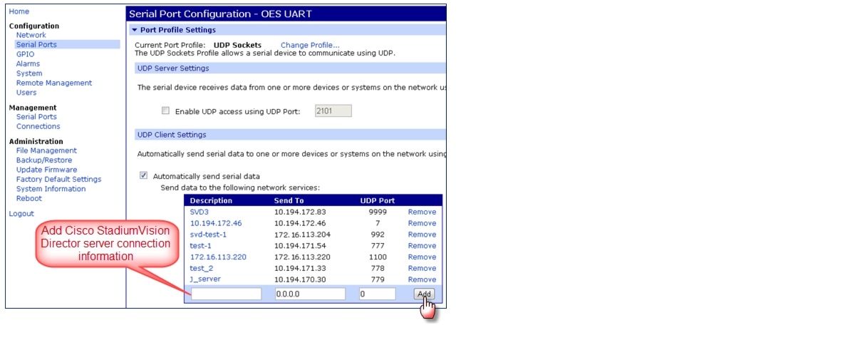
Figure 1 shows an example of the interface for the Serial Port Configuration on the OES ISC9000 controller where the Cisco StadiumVision Director server information must be added.
Figure 1 OES ISC9000 Configuration
Prerequisites for Configuring Daktronics All Sport 5000 Scoreboard Integration
Before you configure the Daktronics All Sport 5000 Scoreboard integration, be sure that the following requirements are met:
•![]() The required Cisco StadiumVision Director server hardware is installed and running Cisco StadiumVision Release 3.0.
The required Cisco StadiumVision Director server hardware is installed and running Cisco StadiumVision Release 3.0.
•![]() The Daktronics Scoreboard controller is installed at the venue (preferably in the Cisco StadiumVision network).
The Daktronics Scoreboard controller is installed at the venue (preferably in the Cisco StadiumVision network).
•![]() The Daktronics Scoreboard controller is reachable by the Cisco StadiumVision Director server on the Internet Protocol (IP) network.
The Daktronics Scoreboard controller is reachable by the Cisco StadiumVision Director server on the Internet Protocol (IP) network.
•![]() A site administrator or Daktronics equipment vendor has added the Cisco StadiumVision Director server IP address in the Daktronics Scoring Timing Interface Application.
A site administrator or Daktronics equipment vendor has added the Cisco StadiumVision Director server IP address in the Daktronics Scoring Timing Interface Application.
Figure 2 shows an example of the DSTI application for the Daktronics controller where the Cisco StadiumVision Director server information must be added.
Figure 2 Daktronics All Sport 5000 Configuration

Workflow Summary for External Content Integration
Note ![]() This workflow assumes that you have completed the required backend network installation and integration at your venue for the external data sources that you plan to support, such as with the NFL GSIS network and Stats-in-a-Box (SIAB) server, or scoreboard device.
This workflow assumes that you have completed the required backend network installation and integration at your venue for the external data sources that you plan to support, such as with the NFL GSIS network and Stats-in-a-Box (SIAB) server, or scoreboard device.
The following steps summarize the overall workflow to integrate data into Cisco StadiumVision Director and display that content on a TV:
Control Panel Setup Interface—External Content Configuration Tab
1. ![]() From the Control Panel, access the External Content interface.
From the Control Panel, access the External Content interface.
2. ![]() Select the data source that you want to configure.
Select the data source that you want to configure.
3. ![]() Complete the network connection configuration.
Complete the network connection configuration.
4. ![]() Modify any configuration options, such as data throttling, as applicable.
Modify any configuration options, such as data throttling, as applicable.
5. ![]() Enable the configuration.
Enable the configuration.
6. ![]() Save the configuration.
Save the configuration.
Note ![]() Whenever you modify and save the External Content configuration, you must activate and restart the application in the Management Dashboard. Cisco StadiumVision Director prompts you to do this, and it can be done at this step or after you finish mapping and formatting your statistics.
Whenever you modify and save the External Content configuration, you must activate and restart the application in the Management Dashboard. Cisco StadiumVision Director prompts you to do this, and it can be done at this step or after you finish mapping and formatting your statistics.
Control Panel Setup Interface—Field Mapping Tab
7. ![]() Complete the field mapping for the selected data source by selecting the available statistics that you want to display in Cisco StadiumVision Director.
Complete the field mapping for the selected data source by selecting the available statistics that you want to display in Cisco StadiumVision Director.
8. ![]() Format each statistic to set the output field name and any other output criteria as desired.
Format each statistic to set the output field name and any other output criteria as desired.

Management Dashboard—External Content Integration
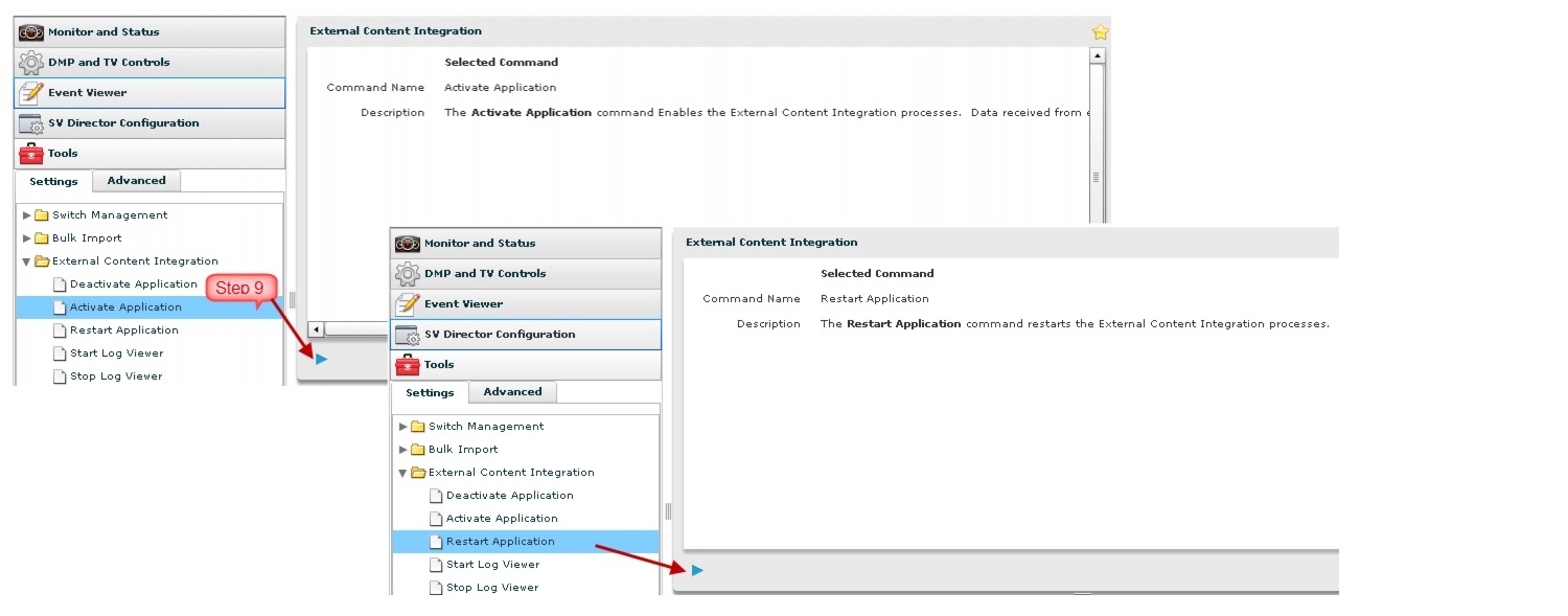
9. ![]() Activate and restart the External Content Integration application from the Management Dashboard.
Activate and restart the External Content Integration application from the Management Dashboard.
Control Panel Widgets Interface
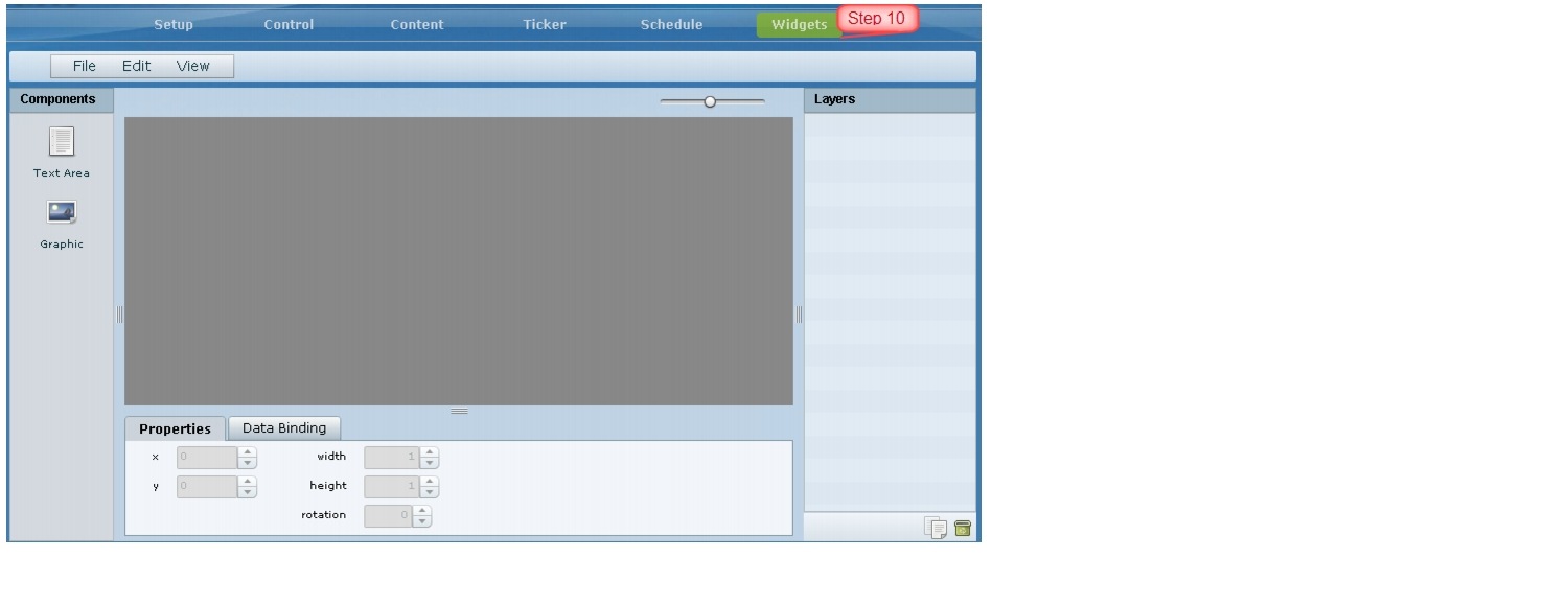
10. ![]() Use the Widgets tool from the Control Panel to design a layout of the statistics that you configured to add graphics and bind/position data fields, and save the widget. See the "Designing the Layout of External Content Using the Widgets Tool" module for more information.
Use the Widgets tool from the Control Panel to design a layout of the statistics that you configured to add graphics and bind/position data fields, and save the widget. See the "Designing the Layout of External Content Using the Widgets Tool" module for more information.
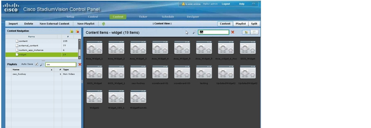
11. ![]() Create a playlist from the Control Panel for the widget that you created. Widgets are categorized in the "By Type" folder under the "widget" type.
Create a playlist from the Control Panel for the widget that you created. Widgets are categorized in the "By Type" folder under the "widget" type.
12. ![]() Create an event script to run the playlist.
Create an event script to run the playlist.
13. ![]() Schedule the script to display the content on a TV just like other pieces of content in Cisco StadiumVision Director.
Schedule the script to display the content on a TV just like other pieces of content in Cisco StadiumVision Director.
How to Configure External Content Integration
This section includes the following tasks:
•![]() Accessing the External Content Integration Interface (required)
Accessing the External Content Integration Interface (required)
•![]() Configuring the Network Connection to the External Content Source (required)
Configuring the Network Connection to the External Content Source (required)
•![]() Configuring Data Throttling (optional)
Configuring Data Throttling (optional)
•![]() Enabling the Data Source Configuration (required)
Enabling the Data Source Configuration (required)
•![]() Activating External Content Integration System-Wide From the Management Dashboard (required)
Activating External Content Integration System-Wide From the Management Dashboard (required)
•![]() Restarting the External Content Integration Application (required)
Restarting the External Content Integration Application (required)
•![]() Selecting Input Statistics and Mapping to Output Fields for Display (required)
Selecting Input Statistics and Mapping to Output Fields for Display (required)
•![]() Verifying the Integration (required)
Verifying the Integration (required)
Accessing the External Content Integration Interface
To access the external content integration interface, complete the following steps:
Step 1 ![]() Log into Cisco StadiumVision Director as an administrator.
Log into Cisco StadiumVision Director as an administrator.
Step 2 ![]() From the main menu, click Control Panel.
From the main menu, click Control Panel.
Step 3 ![]() To access the external content integration interface, do one of the following:
To access the external content integration interface, do one of the following:
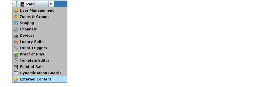
•![]() From the Setup screen, point your cursor to the blank tab on the far right end of the tab list.
From the Setup screen, point your cursor to the blank tab on the far right end of the tab list.

The tab bar automatically scrolls horizontally to reveal the remaining tabs. Click External Content.

•![]() From the Setup screen, click the arrow to open the drop-down list of all tabs and click External Content.
From the Setup screen, click the arrow to open the drop-down list of all tabs and click External Content.
Configuring the Network Connection to the External Content Source
Complete one or more of the following tasks according to the external content sources that your site is going to use:
•![]() Configuring the Connection to the NFL GSIS SIAB Server
Configuring the Connection to the NFL GSIS SIAB Server
•![]() Configuring the Connection to the Scoreboard Controllers
Configuring the Connection to the Scoreboard Controllers
Configuring the Connection to the NFL GSIS SIAB Server
This section includes the following topics:
•![]() Configuring the FTP Connection for NFL Cumulative Statistics
Configuring the FTP Connection for NFL Cumulative Statistics
•![]() Configuring the UDP Connection for the NFL Game Clock
Configuring the UDP Connection for the NFL Game Clock
Configuring the FTP Connection for NFL Cumulative Statistics
Note ![]() Before you configure the FTP connection, be sure that you have the IP address and account credentials for the SIAB server from your NFL GSIS representative.
Before you configure the FTP connection, be sure that you have the IP address and account credentials for the SIAB server from your NFL GSIS representative.
Cisco StadiumVision Director uses FTP port 21 to communicate to the NFL GSIS SIAB server to obtain the GSIS statistics.
To configure the FTP connection to the NFL GSIS SIAB server, complete the following steps:
Step 1 ![]() In the left pane, select the GSIS: NFL,Cumulative Statistics data source type.
In the left pane, select the GSIS: NFL,Cumulative Statistics data source type.
Step 2 ![]() Click the Configuration tab.
Click the Configuration tab.
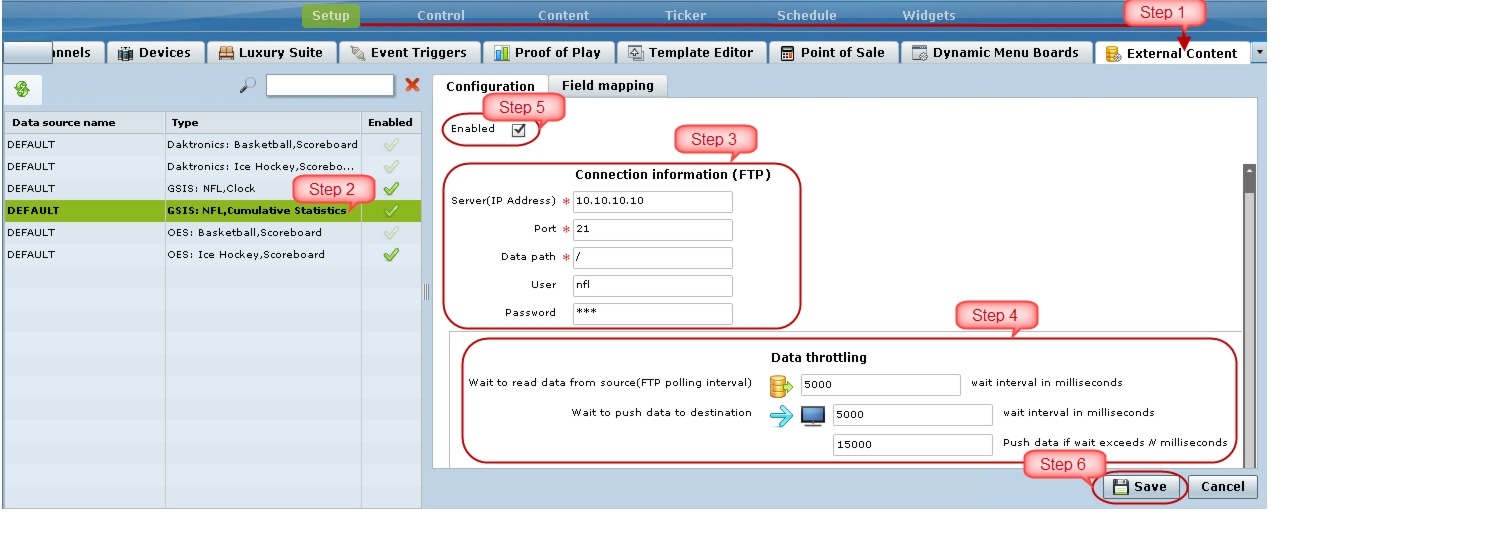
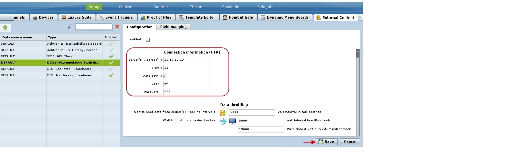
Step 3 ![]() In the Connection information (FTP) section, configure the following options (Figure 3):
In the Connection information (FTP) section, configure the following options (Figure 3):
a. ![]() In the Server (IP Address) box, type the IP address of the SIAB server.
In the Server (IP Address) box, type the IP address of the SIAB server.
b. ![]() In the Port box, type 21.
In the Port box, type 21.
c. ![]() In the Data path box, type "/".
In the Data path box, type "/".
d. ![]() In the User box, type the username for the SIAB server account. The default is nfl.
In the User box, type the username for the SIAB server account. The default is nfl.
e. ![]() In the Password box, type the password for the SIAB server account. The default is nfl.
In the Password box, type the password for the SIAB server account. The default is nfl.
Figure 3 NFL Cumulative Statistics FTP Connection Configuration
Step 4 ![]() Click Save.
Click Save.
A message box appears asking you to restart the application.
Step 5 ![]() If you have completed all of the changes that you want to make on the Configuration tab, restart the application.
If you have completed all of the changes that you want to make on the Configuration tab, restart the application.
For more information, see the "Restarting the External Content Integration Application" section.
Configuring the UDP Connection for the NFL Game Clock
Cisco StadiumVision Director uses UDP port 50000 to communicate to the NFL GSIS SIAB server to obtain the GSIS game clock.
To configure the UDP connection for the NFL game clock, complete the following steps:
Step 1 ![]() In the left pane, select the GSIS: NFL,Clock data source type.
In the left pane, select the GSIS: NFL,Clock data source type.
Step 2 ![]() Click the Configuration tab.
Click the Configuration tab.
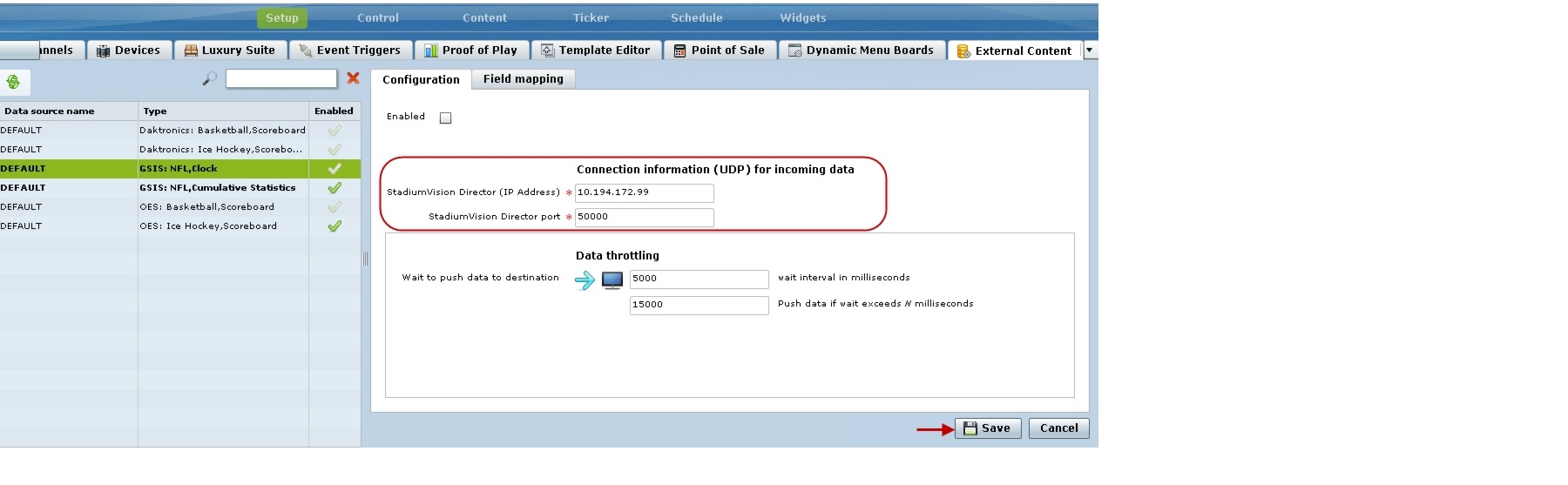
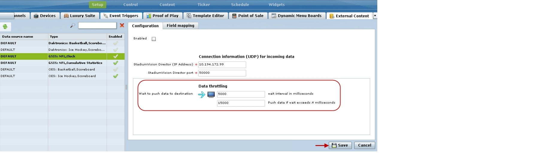
Step 3 ![]() In the Connection information (UDP) section, configure the following options (Figure 4):
In the Connection information (UDP) section, configure the following options (Figure 4):
a. ![]() In the StadiumVision Director (IP Address) box, type the IP address of the Cisco StadiumVision server.
In the StadiumVision Director (IP Address) box, type the IP address of the Cisco StadiumVision server.
Tip ![]() The actual IP address of the Cisco StadiumVision server that you are logged into is provided in shadow, but you must type the address in the box to configure it.
The actual IP address of the Cisco StadiumVision server that you are logged into is provided in shadow, but you must type the address in the box to configure it.
b. ![]() In the Port box, type 50000.
In the Port box, type 50000.
Figure 4 NFL Game Clock UDP Connection Configuration
Step 4 ![]() Click Save.
Click Save.
A message box appears asking you to restart the application.
Step 5 ![]() If you have completed all of the changes that you want to make on the Configuration tab, restart the application.
If you have completed all of the changes that you want to make on the Configuration tab, restart the application.
For more information, see the "Restarting the External Content Integration Application" section.
Configuring the Connection to the Scoreboard Controllers
Cisco StadiumVision Director uses a UDP port to communicate to the controllers to obtain the scoreboard statistics.
Note ![]() The UDP port for the OES ISC9000 Scoreboard controller varies, but the UDP port for the Daktronics All Sport 5000 Scoreboard controller is always 21300. Be sure that you know the UDP port being used for the OES controller.
The UDP port for the OES ISC9000 Scoreboard controller varies, but the UDP port for the Daktronics All Sport 5000 Scoreboard controller is always 21300. Be sure that you know the UDP port being used for the OES controller.
To configure the UDP connection to the scoreboard controllers, complete the following steps:
Step 1 ![]() In the left pane, select the scoreboard data source type that you want to configure.
In the left pane, select the scoreboard data source type that you want to configure.
Step 2 ![]() Click the Configuration tab.
Click the Configuration tab.
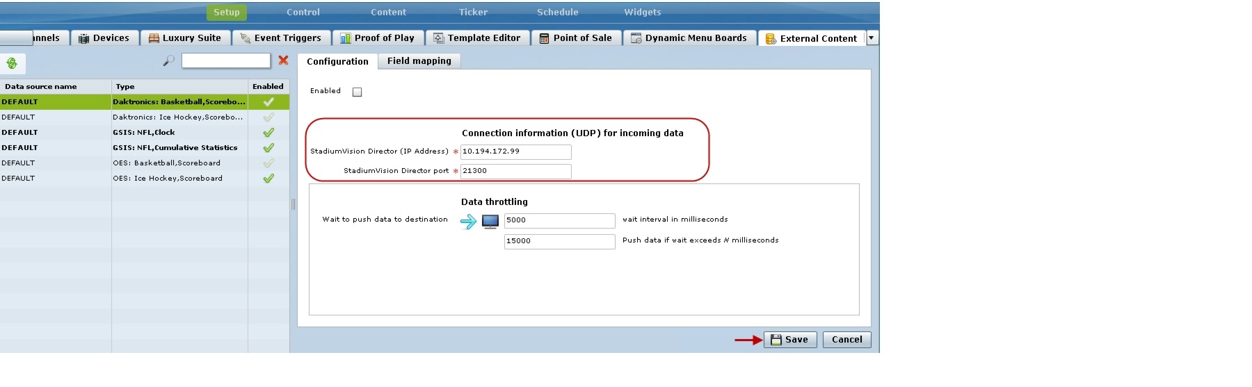
Step 3 ![]() In the Connection information (UDP) section, configure the following options (Figure 5):
In the Connection information (UDP) section, configure the following options (Figure 5):
a. ![]() In the StadiumVision Director (IP Address) box, type the IP address of the Cisco StadiumVision server.
In the StadiumVision Director (IP Address) box, type the IP address of the Cisco StadiumVision server.
Tip ![]() The actual IP address of the Cisco StadiumVision server that you are logged into is provided in shadow, but you must type the address in the box to configure it.
The actual IP address of the Cisco StadiumVision server that you are logged into is provided in shadow, but you must type the address in the box to configure it.
b. ![]() In the Port box, type the UDP port number used to connect to the scoreboard controller.
In the Port box, type the UDP port number used to connect to the scoreboard controller.
Note ![]() For the Daktronics All Sport 5000 Scoreboard controller, the UDP port is always 21300 (Figure 5).
For the Daktronics All Sport 5000 Scoreboard controller, the UDP port is always 21300 (Figure 5).
Figure 5 Daktronics Scoreboard Controller UDP Connection Configuration
Step 4 ![]() Click Save.
Click Save.
A message box appears asking you to restart the application.
Step 5 ![]() If you have completed all of the changes that you want to make on the Configuration tab, restart the application.
If you have completed all of the changes that you want to make on the Configuration tab, restart the application.
For more information, see the "Restarting the External Content Integration Application" section.
Configuring Data Throttling

The following data throttling options are provided in Cisco StadiumVision Director:
•![]() Wait to read data from source (FTP polling interval)—NFL cumulative statistics only
Wait to read data from source (FTP polling interval)—NFL cumulative statistics only
Specifies how often (in milliseconds) to retrieve data from the SIAB server. The recommended value is 5000 ms (5 seconds).
•![]() Wait to push data to destination
Wait to push data to destination
Specifies the frequency with which the data is multicast to all DMPs in the Cisco StadiumVision Director server. The recommended value is 5000 ms (5 seconds).
•![]() Push data if wait exceeds
Push data if wait exceeds
If there has not been any change in data since the last poll, then this throttle specifies the longest amount of time to wait before sending the multicast of unchanged data to all DMPs. The recommended value is 15000 ms (15 seconds).
To configure data throttling, complete the following steps:
Step 1 ![]() In the left pane, select the data source type.
In the left pane, select the data source type.
Step 2 ![]() Click the Configuration tab.
Click the Configuration tab.
The configuration for the selected data source appears in the right pane.
Step 3 ![]() In the Data throttling section, set one or more of the throttling values.
In the Data throttling section, set one or more of the throttling values.
Figure 6 shows a throttling configuration example for the NFL cumulative statistics data source.
Figure 6 NFL Cumulative Statistics Throttling Configuration Example
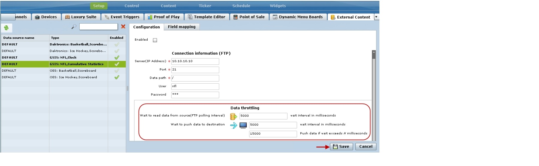
Figure 7 shows a throttling configuration example for the NFL clock UDP data source.
Note ![]() The same throttling options are available for the scoreboard controller UDP connections.
The same throttling options are available for the scoreboard controller UDP connections.
Figure 7 NFL Clock Throttling for UDP Configuration Example
Step 4 ![]() Click Save.
Click Save.
A message box appears asking you to restart the application.
Step 5 ![]() If you have completed all of the changes that you want to make on the Configuration tab, restart the application.
If you have completed all of the changes that you want to make on the Configuration tab, restart the application.
For more information, see the "Restarting the External Content Integration Application" section.
Enabling the Data Source Configuration
By default, external data collection and configuration is disabled. Once you have completed your configuration, you must both enable the data source and save the configuration to allow collection of the data.
Note ![]() Real-time data collection from the SIAB server will not begin until the External Content Integration application has been both enabled and restarted in Cisco StadiumVision Director. For more information, see the "Activating External Content Integration System-Wide From the Management Dashboard" section and "Restarting the External Content Integration Application" section.
Real-time data collection from the SIAB server will not begin until the External Content Integration application has been both enabled and restarted in Cisco StadiumVision Director. For more information, see the "Activating External Content Integration System-Wide From the Management Dashboard" section and "Restarting the External Content Integration Application" section.
To enable the data source configuration, complete the following steps:
Step 1 ![]() In the left pane, select the GSIS data source type.
In the left pane, select the GSIS data source type.
Step 2 ![]() Click the Configuration tab.
Click the Configuration tab.
The configuration for the selected data source appears in the right pane.
Step 3 ![]() At the top of the pane, select the Enabled checkbox.
At the top of the pane, select the Enabled checkbox.
A checkmark appears in the box when the data source is enabled.
Step 4 ![]() Click Save.
Click Save.
A message box appears asking you to restart the application.
Step 5 ![]() If you have completed all of the changes that you want to make on the Configuration tab, restart the application.
If you have completed all of the changes that you want to make on the Configuration tab, restart the application.
For more information, see the "Restarting the External Content Integration Application" section.
Activating External Content Integration System-Wide From the Management Dashboard
By default, External Content Integration is disabled system-wide in Cisco StadiumVision Director. After you have saved and enabled your data source configuration, you must activate the application and restart it from the Management Dashboard before data collection can begin.
The External Content Integration application must only be activated once to deploy it in the Cisco StadiumVision Director server. Once the External Content Integration application has been activated in the system, then any time the configuration has been changed, the application only must be restarted.
To activate External Content Integration system-wide, complete the following steps:
Step 1 ![]() Log into Cisco StadiumVision Director as an administrator.
Log into Cisco StadiumVision Director as an administrator.
Step 2 ![]() From the Cisco StadiumVision Director main menu, click Management Dashboard.
From the Cisco StadiumVision Director main menu, click Management Dashboard.
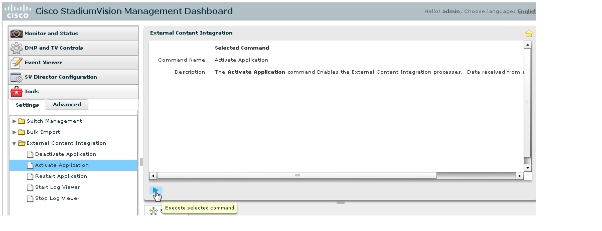
Step 3 ![]() Using the Management Dashboard drawers, go to Tools > Settings > External Content Integration.
Using the Management Dashboard drawers, go to Tools > Settings > External Content Integration.
Step 4 ![]() Select Activate Application.
Select Activate Application.
Step 5 ![]() Click the Play button.
Click the Play button.
Step 6 ![]() When the confirmation message box appears, click Ok to run the command.
When the confirmation message box appears, click Ok to run the command.
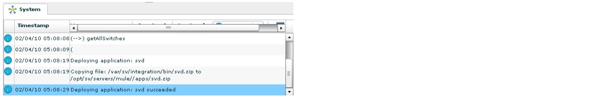
Step 7 ![]() To verify the application activation, look for the success message in the log display area of the screen.
To verify the application activation, look for the success message in the log display area of the screen.
Step 8 ![]() After the processing has completed, select Restart Application.
After the processing has completed, select Restart Application.
For more information, see the "Restarting the External Content Integration Application" section.
Restarting the External Content Integration Application
Any time that you have made a change to the External Content Integration settings on the Configuration tab for external data sources, you must restart the application from the Cisco StadiumVision Director Management Dashboard.
When you save the configuration, a message is displayed as a reminder to restart:

Note ![]() Changes to the data source field mapping only need to be saved, but the application does not have to be restarted. However, if for some reason you did not do a restart of the application after making changes in the Configuration tab before going on to save changes in Field mapping, then you also will see this message about the required restart at the time you save the Field mapping.
Changes to the data source field mapping only need to be saved, but the application does not have to be restarted. However, if for some reason you did not do a restart of the application after making changes in the Configuration tab before going on to save changes in Field mapping, then you also will see this message about the required restart at the time you save the Field mapping.
To restart the External Content Integration Application, complete the following steps:
Step 1 ![]() Log into Cisco StadiumVision Director as an administrator.
Log into Cisco StadiumVision Director as an administrator.
Step 2 ![]() From the Cisco StadiumVision Director main menu, click Management Dashboard.
From the Cisco StadiumVision Director main menu, click Management Dashboard.
Step 3 ![]() Using the Management Dashboard drawers, go to Tools > Settings > External Content Integration.
Using the Management Dashboard drawers, go to Tools > Settings > External Content Integration.
Step 4 ![]() Select Restart Application.
Select Restart Application.
Step 5 ![]() Click the Play button to run the command.
Click the Play button to run the command.

Step 6 ![]() When the confirmation message box appears, click Ok to run the command.
When the confirmation message box appears, click Ok to run the command.
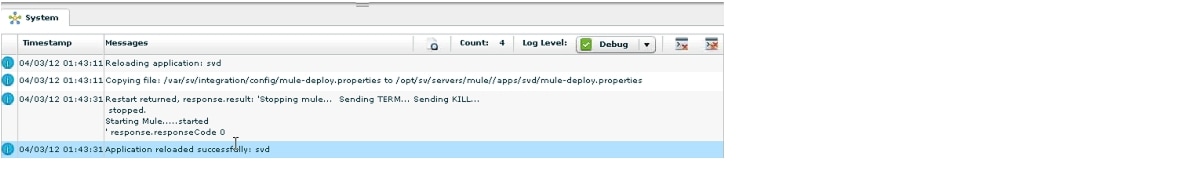
Step 7 ![]() To verify the application activation, look for the success message in the log display area of the screen.
To verify the application activation, look for the success message in the log display area of the screen.
Selecting Input Statistics and Mapping to Output Fields for Display
To select input statistics and map to output fields for display, complete the following steps:
Step 1 ![]() In the left pane, select the GSIS data source type.
In the left pane, select the GSIS data source type.
Step 2 ![]() Click the Field Mapping tab.
Click the Field Mapping tab.
The Input field displays the name of the data file for the selected NFL data source (CumulativeStatisticsFile or GameClock).
Step 3 ![]() To view the available statistics, click the arrow beside the data file name to expand the list.
To view the available statistics, click the arrow beside the data file name to expand the list.
Step 4 ![]() With your mouse, select a statistic and drag-and-drop it to the Output Fields panel on the right.
With your mouse, select a statistic and drag-and-drop it to the Output Fields panel on the right.
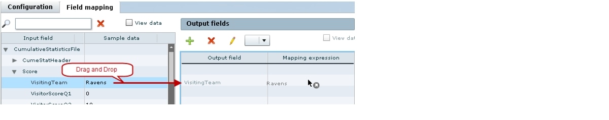
The Add Output field dialog box is displayed.
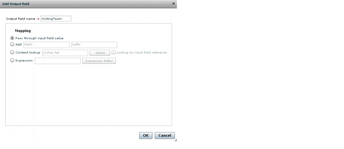
Step 5 ![]() Modify the Output field name or other mapping options as needed.
Modify the Output field name or other mapping options as needed.
For more information, see the "Modifying the Output Format of a Statistic" section.
Step 6 ![]() Continue to select and add statistics to the Output fields panel.
Continue to select and add statistics to the Output fields panel.
Step 7 ![]() Click Save.
Click Save.
Verifying the Integration
This section includes the following topics:
•![]() Verifying Receipt of Real-Time Data
Verifying Receipt of Real-Time Data
•![]() Verifying the Integration Broker Service Status
Verifying the Integration Broker Service Status
Verifying Receipt of Real-Time Data
Assuming that your network connection to the external data source is available and you have enabled the data source, real-time data is collected after you both activate and restart the application in the Management Dashboard.
To verify the receipt of real-time data, complete the following steps:
Step 1 ![]() From the External Content Integration interface, select the data source that you want to verify.
From the External Content Integration interface, select the data source that you want to verify.
Step 2 ![]() Click Field mapping.
Click Field mapping.
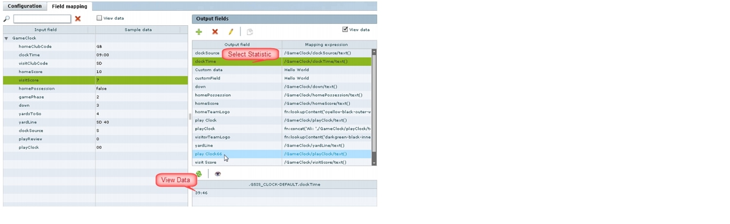
Step 3 ![]() In the Output fields panel, select the View data checkbox.
In the Output fields panel, select the View data checkbox.
Note ![]() The interface can show sample data and real-time data. Figure 8 shows which View data checkbox in the interface corresponds to each type of data.
The interface can show sample data and real-time data. Figure 8 shows which View data checkbox in the interface corresponds to each type of data.
Figure 8 View Data Checkbox for Sample Data Versus Real-Time Data

Step 4 ![]() In the Output field, select a statistic.
In the Output field, select a statistic.
Step 5 ![]() Observe the data value at the bottom of the panel for the selected statistic.
Observe the data value at the bottom of the panel for the selected statistic.
Figure 9 shows an example of real-time data for the NFL GSIS clockTime statistic.
Figure 9 Clock Time Real-Time Data Statistic
Step 6 ![]() Click the Refresh icon (Figure 10) and observe that the value is changing to confirm receipt of real-time data.
Click the Refresh icon (Figure 10) and observe that the value is changing to confirm receipt of real-time data.
Figure 10 Refresh Icon for Real-Time Data

Verifying the Integration Broker Service Status
To verify the integration broker service status, complete the following steps:
Step 1 ![]() From the Management Dashboard, go to the Service Alerts pane in the bottom right corner.
From the Management Dashboard, go to the Service Alerts pane in the bottom right corner.
Step 2 ![]() Navigate to find the Integration Broker service name and observe its status icon.
Navigate to find the Integration Broker service name and observe its status icon.
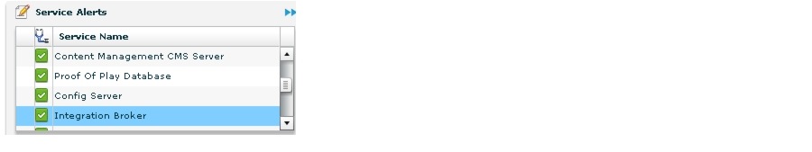
When the icon is green, the External Content Integration service is successfully activated.
 Feedback