RTLS Guidance for Cisco FRA and Cisco Spaces with Stanley Healthcare
Available Languages
Bias-Free Language
The documentation set for this product strives to use bias-free language. For the purposes of this documentation set, bias-free is defined as language that does not imply discrimination based on age, disability, gender, racial identity, ethnic identity, sexual orientation, socioeconomic status, and intersectionality. Exceptions may be present in the documentation due to language that is hardcoded in the user interfaces of the product software, language used based on RFP documentation, or language that is used by a referenced third-party product. Learn more about how Cisco is using Inclusive Language.
Cisco is the market leader in enterprise wireless networking, with best-in-class hardware and software solutions for tackling ever more complex and challenging environments. Cisco Spaces is the world’s fastest-growing cloud-based location service, helping businesses and enterprises drive outcomes at scale. Cisco Spaces is the next evolution of indoor location systems, built on decades of expertise gained through the Cisco Mobility Services Engine (MSE) and Cisco Connected Mobile Experiences (CMX) platforms.
Real-Time Location Services (RTLS) have been used in the healthcare industry for a variety of mission-critical applications over the years. Solutions today go beyond asset tracking alone, providing services such as patient and staff safety, employee duress, newborn security, and environmental monitoring. Stanley Healthcare is the leader in RTLS solutions and provides customers with simple, scalable, and reliable systems for those critical challenges.
Cisco Spaces and Stanley Healthcare have partnered together for a complete end-to-end indoor location and RTLS solution for healthcare providers.
With a wide range of feature sets across the networking portfolio, customers may need to weigh some pros and cons as they implement individual features for their use cases. One example, addressed in this paper, is Cisco’s Flexible Radio Assignment (FRA) feature. FRA, along with FRA-capable Access Points (APs), identifies and corrects the oversaturation of 2.4 GHz radios, which causes interference and degraded performance for the Wi-Fi network. By assigning these redundant 2.4 GHz radios to other beneficial roles, for example, as a 5 GHz radio or dedicated monitor radio, FRA maintains the network fidelity and redeploys otherwise unused resources. Wi-Fi RFID tags in the Stanley Healthcare ecosystem operate explicitly in 2.4 GHz, and the density and stability of the 2.4 GHz Wi-Fi network is critical to accurate tracking of the Stanly AeroScout Tag deployments. This paper explains why using the default FRA configurations on a Cisco network may cause degraded location accuracy for Wi-Fi tags in the Stanley AeroScout Location Engine. It provides the joint Cisco and Stanley suggested best practices for achieving both a balanced network and high-fidelity tag location.
Cisco Flexible Radio Assignment (FRA)
Some Cisco access point models support flexible (XOR) radios and offer the ability to dynamically or statically support different radio “roles.” This allows FRA to right-size 2.4 GHz coverage while also offering additional value and services such as increased capacity, reduced contention, and higher-density performance for clients. In order to dynamically control the roles that these radios perform, the Radio Resource Management (RRM) algorithm uses FRA to analyze the Neighbor Discovery Protocol (NDP) measurements and dynamically assign roles to the XOR radios in APs. Customers can also choose to turn off FRA or assign static roles to the radios as needed. The following AP models contain radios that can be controlled by the FRA algorithm:
● Cisco Aironet 2800 Series, 3800 Series, and 4800 Series
● Cisco Catalyst 9120AX Series and 9130AX Series
Radios in these APs can be in one of these roles at a time:
● Client-serving mode (serving in 2.4 GHz)
● Client-serving mode (serving in 5 GHz)
● Monitor mode
In general, FRA brings many benefits to any wireless environment, especially for high-density environments, and should be turned on by default. Some of the most important benefits of FRA include:
● Reducing excessive 2.4 GHz radios to avoid interference
● Increasing the capacity of the network with additional 5 GHz radios
● Dynamically switching to dedicated monitor mode to provide additional input to RRM, rogue detection, Cisco Adaptive Wireless Intrusion Prevention System (aWIPS), and spectrum analysis
● Redeploying the hardware rather than simply turning it off
● Providing knobs to control the thresholds to allow configurability for adapting to different environments
While FRA brings many benefits to the traditional Wi-Fi client network use case, RFID tag location is a different and very specific use case. In many environments, removing APs from service or dynamically changing the APs’ radio roles is desired. However, an RFID tag’s accuracy depends on being heard by multiple nearby APs on 2.4 GHz. The location calculation engines uses the calibrated locations of these APs and combine several tag signal reports to derive the tags’ map location in reference to these APs. Good accuracy generally requires four or more listening APs, with more being better. When FRA changes the available APs dynamically, it can cause calibration changes in the Location Engine and lead to degraded performance of the tag location solution. This applies to any RFID solution and is not limited to the superior performance of Stanley AeroScout Tags.
Cisco Spaces and Stanley Healthcare architecture
This section provides a high-level overview of the architecture of Cisco Spaces with Stanley Healthcare. For more details, please refer to the Cisco and Stanley Healthcare documentation.
Components involved in the architecture
● Cisco infrastructure:
◦ Cisco access points
◦ AireOS or Catalyst 9800 Series Wireless LAN Controllers (WLCs)
◦ Cisco Spaces Connector
◦ Cisco Spaces (Extend or Act license)
● Stanley infrastructure:
◦ AeroScout Location Engine (ALE) Server
◦ AeroScout Engine Manager
◦ MobileView Server and licenses
● End devices:
◦ AeroScout Wi-Fi (RFID) Tags
◦ Other Wi-Fi devices such as laptops, smartphones, etc.
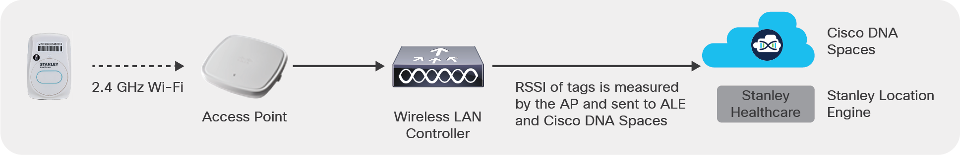
RFID tags are battery-operated devices available in multiple form factors that transmit periodic 802.11-compliant beacon messages on either a single or multiple (configurable) 2.4 GHz Wi-Fi channels without needing to associate to an SSID. While some tags can also behave as a client and associate to an SSID, the majority of tags do not associate and simply send a periodic message that is heard by the APs. Each AP reports all of the tag data it hears to the WLC, Cisco Spaces, and the Stanley Location Engine.
While the tags can be configured to transmit in a single channel, most customers generally use the default configuration to transmit in channels 1, 6, and 11 to maximize the number of APs hearing the tag, since most wireless deployments use that channel scheme in the 2.4 GHz band. The tag would then repeat the same message in all three channels in a single cycle. Some tags also have sensors and buttons to send telemetry and alerts for specific use cases, and that information is sent in the same 802.11-compliant message.
Customers can also selectively deploy Stanley exciters as needed. That way, they can achieve carpet-wide coverage with both Wi-Fi and point coverage with exciters for a more robust use case and accuracy.
Measuring and reporting the Received Signal Strength Indication (RSSI) to Cisco Spaces and Stanley Aeroscout Location Engine
Understanding how APs scan and report RSSI
As with any 802.11 traffic, for a tag message to be heard and reported, an AP needs to be in range and on the same channel at the same time that the tag transmits its message. If the AP is off channel for some reason, the tag message is missed by that AP.
There are essentially two ways that an AP will listen for the tag messages operating across channels 1, 6, and 11 in the 2.4 GHz band:
● Scan via client-serving radio:
The AP’s 2.4 GHz radio (slot 0) is available on that channel all the time. If the radio is listening on the same channel, the probability of missing the tag message is low and there is a high chance of the AP catching most tag messages.
● Off-channel scanning:
APs also go off channel periodically to scan all of the channels for RRM and security-related features. If the AP is scanning off-channel traffic when a tag is transmitted on the same channel, the AP can hear the tag and report the data. Off-channel scanning relies on opportunistic timing, meaning that the probability of hearing the tag is significantly reduced.
For example:
In the figure below, if the tags are transmitting only at channel 1, AP1 would be able to listen for the tags only during the off-channel scanning of channel 1 if the tags happen to transmit at the same time. However, AP2 should be able to listen for the tags in a much more deterministic fashion using a dedicated radio assigned to channel 1.
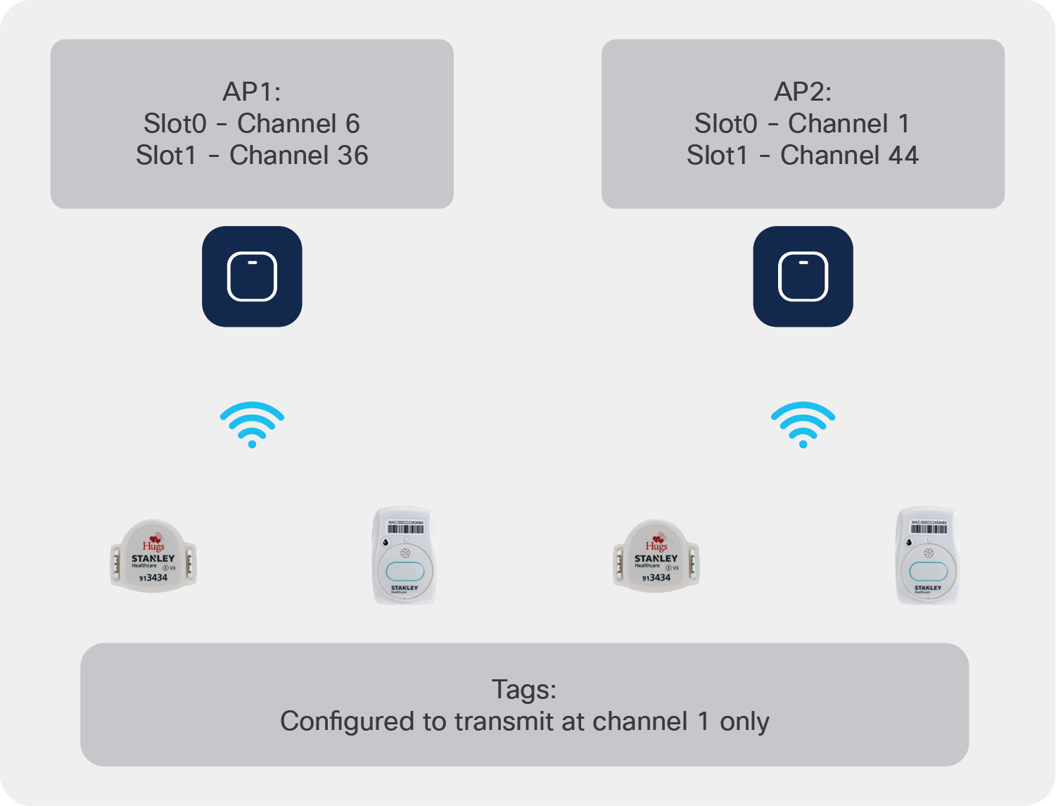
Tags transmitted on channel 1 are more likely to be head by AP2
Cisco Spaces and Stanley Healthcare architecture
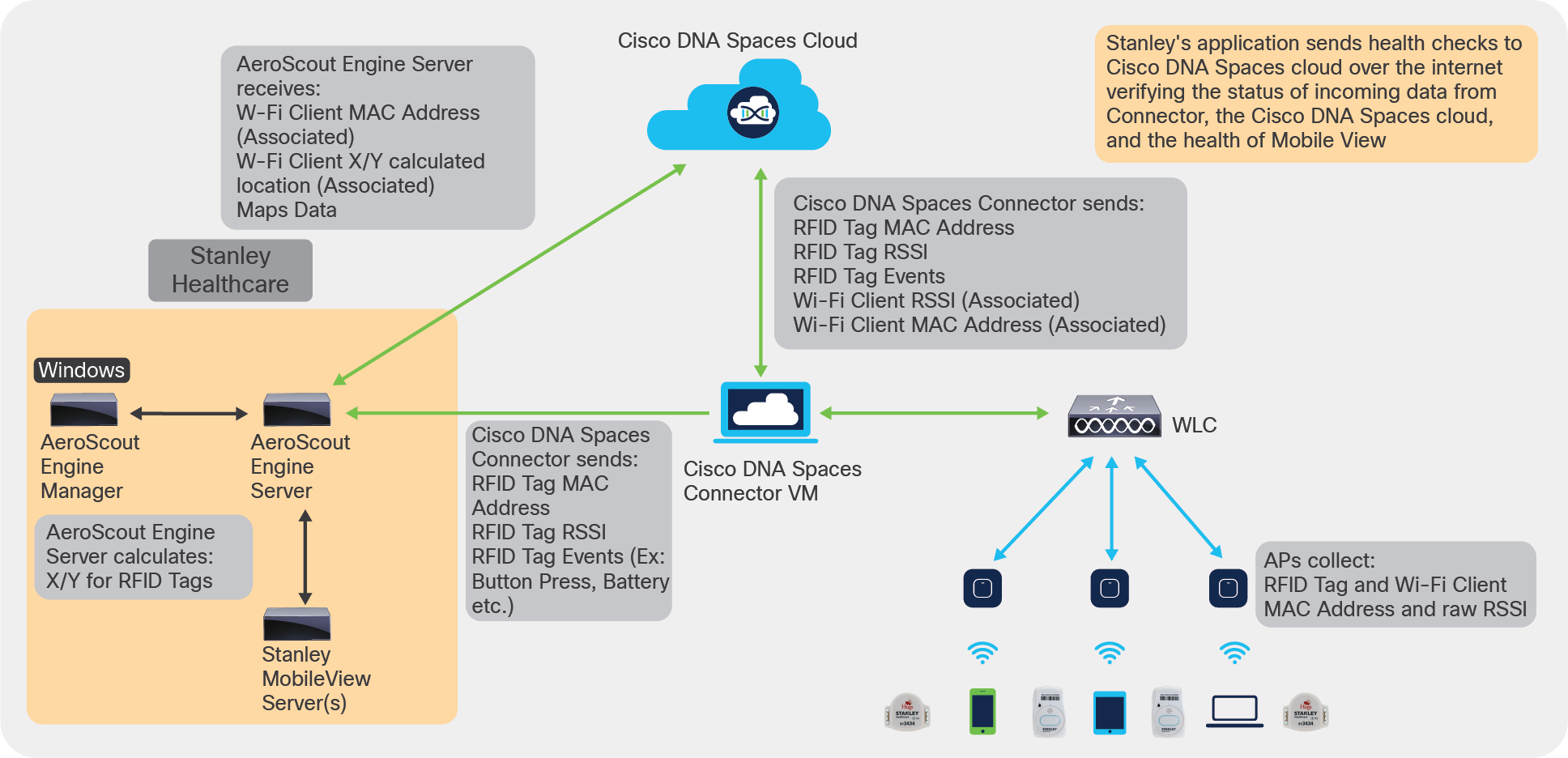
● APs listen for the tag messages and report the RSSI of the tag heard, along with any telemetry information sent by the tag.
● The messages, along with other Wi-Fi client data, are sent to the Cisco Spaces Connector, which in turn sends only the RFID tag-related information to the AeroScout Engine Server via the Local Firehose channel.
● Stanley uses that data to calculate the location of the tag as well as provide additional RTLS use cases.
Cisco Spaces and Stanley Healthcare architecture
Impact of FRA on location calculation
The previous discussion of the architecture and how APs listen for tag messages is important in understanding how and why FRA can create potential issues when it comes to tracking Wi-Fi RFID tags. As we explained, an AP needs to listen for messages on channel (preferred) or rely on off-channel scanning (less optimal) to capture the tag messages. (A dedicated monitor mode interface on an AP does improve off-channel scanning by being dedicated to scanning the entire band, which results in longer dwells and faster rescans and improves the overall off-channel performance, but customers should understand that for mission-critical safety and security solutions using RTLS, it will not be as good as having dedicated on-channel listening radios.)
For APs that have FRA radios (Aironet 2800, 3800, and 4800 Series and Catalyst 9120AX and 9130AX Series), FRA could decide that there is an excessive number of 2.4 GHz radios operating in close proximity. This excess can lead to channel exhaustion (there are only three usable channels in 2.4 GHz) and oversaturation, causing severe interference and degrading performance for all radios in the band. In this case FRA can convert XOR (dual-band) radios to serve in 5 GHz or as a monitor interface or, in the case of the Catalyst 9130AX Series, simply as a monitor for 2.4 GHz.
In either of these cases, the primary mode of listening to the tag is potentially changed, and the AP is now scanning off-channel, which can result in missed tag messages.
Catalyst 9120AX and 9130AX Series APs scan all channels for both bands through the Cisco RF ASIC radio, which allows the AP to dwell in each channel for a longer duration. It will still stay on channel with the client-serving radios, where the tags are transmitting for a limited time. Even in the best-case scenario, in which the tags are configured to transmit in channels 1, 6, and 11, relying only on off-channel scanning reduces the probability of capturing the tag data, as the AP would be scanning up to 13 channels on 2.4 GHz and up to 25 or more channels on the 5 GHz band. While the AP can capture the messages when it’s listening on the correct channel, it could potentially miss messages, which can result in degraded RTLS performance.
For example:
In the figure below, FRA has changed the slot 0 radio of AP1 to client-serving 5 GHz, and changed slot 0 of AP2 to monitor mode. Slot 0 of AP3 continues to serve clients on channel 6.
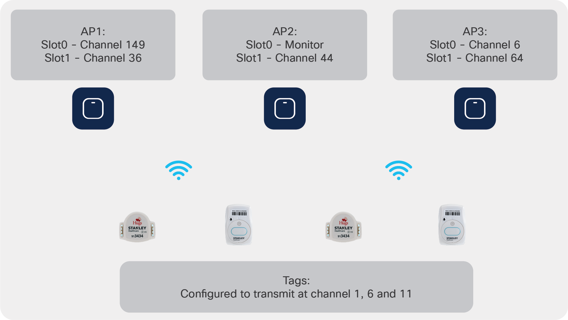
When FRA changes radio roles, RTLS can experience location inaccuracy
In this case, AP1 and AP2 rely only on the off-channel scanning cycles to be able to capture the tag messages. AP3 would be able to capture most of the tag messages on channel 6 and also intermittently capture some messages on channels 1 and 11 during its off-channel cycles.
Cisco Spaces calculates location of wireless endpoints like 5GHz and 2.4GHz WiFi clients and RFID tags based on the real time information received by the APs. Due to this, when an AP whose radio bands are changed dynamically by FRA, their input dataset to calculate location becomes limited and Cisco Spaces calculates the estimated location based on other APs. However, in order to provide a good accuracy for RFID tag location and messages, RTLS solutions like Stanley require a thorough fingerprinting (recording) as the first step in the Location Engine. During this first step, which is similar to RF fingerprinting, the Stanley engine needs to be provided with data on all the APs that hear a tag in a particular location. That way, the system is fed with the accurate location and the corresponding data of how different APs heard the tag in the location. They need to repeat this process in multiple locations in a hospital or other physical space. Due to this fingerprint mapping, whenever an AP stops reporting the tag in a consistent manner due to a radio role change via FRA, it causes a higher degree of location inaccuracy with RTLS because the Stanley system expects that AP from the fingerprinting database to continuously report that tag.
Best practices for RTLS with Cisco infrastructure
The following are some best practices that can help you achieve a robust RTLS solution in your healthcare environment. Of course, depending on your use case, some tweaks may be needed, but in general:
● Add all relevant WLCs in Cisco Spaces and make sure RFID tracking is on. Make sure you have highly accurate maps with correct scale (length and width), AP positioning, etc. Add exclusion and inclusion zones with relevant thick walls, etc. Any location calculation is only as good as the data provided.
● If capturing as many tag messages as possible is a mission-critical and primary use case, as with infant protection and employee duress, turn off FRA and keep the APs’ 2.4 GHz radios on and in client-serving mode.
● FRA should be turned off for specific APs that serve the RTLS use case. It can continue to be used for other APs where better Wi-Fi experience and capacity is desired.
● If you are using Wave 1 APs, turn on Tracking Optimized Monitor Mode (TOMM) on the APs for enhanced tag tracking performance by placing some APs in monitor mode and limiting the off-channel scanning only to channels 1, 6, and 11. Currently, TOMM is not available in Wave 2 or Catalyst APs.
● Consider alternatives such as leveraging Bluetooth Low Energy (BLE) tags or adding exciters for improved tracking performance that is not impacted by FRA.
● You can limit the channels an AP will scan off-channel by specifying that only Dynamic Channel Assignment (DCA) channels be scanned (generally, channels 1, 6, and 11 in 2.4 GHz). This doesn’t directly improve the tag listening probability, since the AP will now scan only three channels but would still do that in full scan duration. However, it can help keep the AP on channel for longer and, when off channel, keep it focused only on the selected channels, which can help a little. Note that if the AP radio is not even serving in 2.4 GHz, this will not help much. On the other hand, in TOMM, the entire AP is a dedicated monitor mode AP and dwells for a longer time in selected channels only, thereby increasing the probability of capturing the tag’s messages. Nevertheless, if needed, you can limit the channels to DCA channels from the WLC GUI:
In the AireOS WLC GUI:
Under Wireless -> 802.11a -> RRM -> General -> Noise/Interference/Rogue/CleanAir/SI Monitoring drop-down.
In the Catalyst WLC GUI:
Under Configuration -> RRM -> 2.4 GHz Band -> General -> Noise/Interference/Rogue/CleanAir/SI Monitoring drop-down.
● For critical solutions such as infant protection, patient protection, and others, we recommend changing the WLC’s RSSI reporting interval from the default 2 seconds to 1 second. To make this change, issue the following commands in the WLC’s CLI:
In the AireOS CLI:
(AireOSWLC)> config nmsp notification interval rssi rfid 1
In the Cisco IOS XE WLC CLI:
IOS-XE WLC# config terminal
IOS-XE WLC(config)# nmsp notification interval rssi rfid 1
Configuration steps to turn off FRA via the CLI
Use the following configuration steps on the Cisco WLC to turn off FRA, or keep it on but statically keep some APs in client-serving 2.4 GHz mode so it does not change dynamically.
1. Before making any changes, it’s best to save the running configuration and collect the following FRA-related outputs:
(AireOS) “sh run-config”
(IOS-XE) “sh tech wireless”
(AireOS) “sh adv fra”
(IOS-XE)”sh ap fra”
2. On the WLC console, execute:
(AireOS) “config advanced fra revert all static 2.4GHz”
(Cisco IOS XE) “ap fra revert all static 24ghz”
a. This command will place all the XOR radios in 2.4 GHz client-serving “static” mode, which means that the FRA algorithm cannot change the radio assignment. It also allows FRA to calculate the coverage overlap factor (FRA operates only on 2.4 GHz to identify redundant radios).
b. Verify using the “sh adv fra” command on AireOS or “sh ap fra” on Cisco IOS XE controllers.
AP Name MAC Address Slot Current Band COF % Sensor % Suggested Mode
--------------------- ------------ ---------------- ---- -------- ----------
C9120i_F_.e4:25:dd:a0 c0:64:e4:25:dd:a0 0 2.4GHz None (Static)
2802i_F_.26.ED.D0 00:f2:8b:26:ed:d0 0 2.4GHz None None (Static)
3802i_F_.39.CA.20 00:a2:ee:39:ca:20 0 2.4GHz None None (Static)
3. Ensure that FRA is enabled at the global level.
(AireOS) >show advanced fra (“sh ap fra” on Cisco IOS XE)
FRA State........................................ Enabled
FRA Operation State.............................. Up
FRA Sensitivity.................................. high (90%)
FRA Interval..................................... 1 Hour(s)
Last Run....................................... 2925 seconds ago
Last Run Time.................................. 0 seconds
Service Priority................................. Coverage
a. If it is not, enable it as follows:
(AireOS) “config advanced fra enable”
(Cisco IOS XE) “config t”, then “ap fra” or enable via the GUI
4. Once FRA is configured, initiate a DCA restart. The restart will allow FRA to run at the same interval that the start-up DCA algorithm will run at – every 10 minutes. (Steady-state FRA runs only once per hour).
(AireOS) “config 802.11a/802.11b channel global restart”
(Cisco IOS XE) “ap dot11 5ghz rrm dca”
5. Monitor progress using the command:
(AireOS) “show advanced 802.11a channel”
Leader Automatic Channel Assignment
Channel Assignment Mode........................ AUTO
Channel Update Interval........................ 600 seconds [startup]
Anchor time (Hour of the day).................. 0
Update Contribution
Noise........................................ Enable
Interference................................. Enable
Load......................................... Disable
Device Aware................................. Enable
CleanAir Event-driven RRM option............... Disabled
Channel Assignment Leader.......... Cisco_af:aa:72 (192.168.10.20)
Last Run....................................... 225 seconds ago
Last Run Time.................................. 0 seconds
DCA Sensitivity Level.......................... STARTUP (5 dB)
DCA Aggressive Remaining Cycle................. 10 (100 minutes)
DCA 802.11n/ac Channel Width................... 40 MHz
DCA Minimum Energy Limit....................... -95 dBm
(Cisco IOS XE) “sh ap dot11 5ghz channel”
Leader Automatic Channel Assignment
Channel Assignment Mode : AUTO
Channel Update Interval : 600 seconds
Anchor time (Hour of the day) : 0
Channel Update Contribution
Noise : Enable
Interference : Enable
Load : Disable
Device Aware : Disable
CleanAir Event-driven RRM option : Enabled
CleanAir Event-driven RRM sensitivity : LOW
CleanAir Event-driven RRM Rogue option : Enabled
CleanAir Event-driven RRM Rogue Duty Cycle : 40
Channel Assignment Leader : C9800-L_17_3 (192.168.10.21)
Last Run : 23 seconds ago
DCA Sensitivity Level : MEDIUM : 15 dB
DCA Aggressive Remaining Cycle : 9(90 minutes)
DCA 802.11n/ac Channel Width : best
DBS Max Channel Width : 40 MHz
DCA Minimum Energy Limit : -95 dBm
6. The counter will continue to count down and keep track of aggressive DCA cycles until it finishes and places DCA back into the medium sensitivity setting.
7. Once complete, on the WLC console, issue this command:
(AireOS) “sh adv fra” output
(Cisco IOS XE) “sh ap fra”
Using the FRA output list to identify redundant APs, you can manually leave these in client-serving mode or even monitor mode –both will prevent FRA from performing further scrutiny.
In the Cisco IOS XE controller, there is also the concept of FRA freeze. This can be used to freeze the FRA configuration and prevent consecutive FRA runs from changing the solution.
Example:
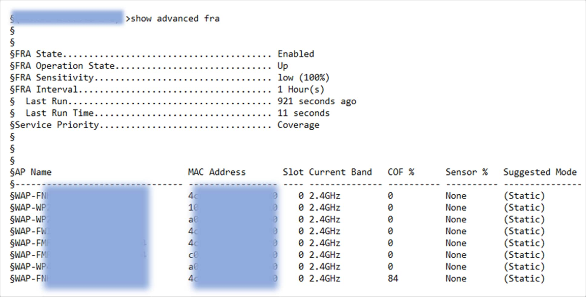
Viewing the FRA output
Configuration steps to turn off FRA via the UI
AireOS WLC:
Disable FRA under Wireless -> Advanced -> Flexible Radio Assignment
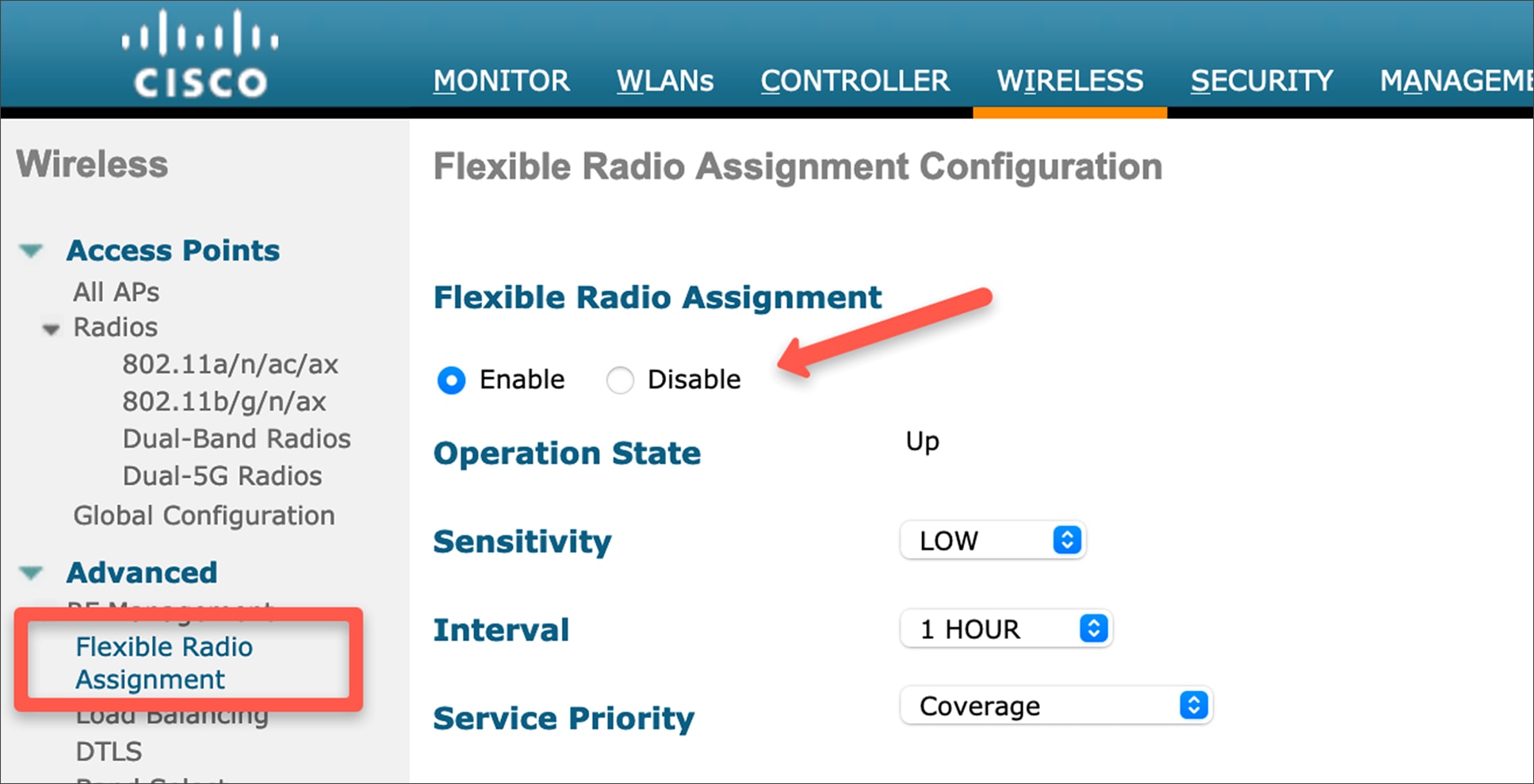
Disabling FRA in AireOS
Cisco IOS XE (Catalyst 9800 Series) WLC:
Turn off FRA under Configuration -> Radio Configurations -> RRM
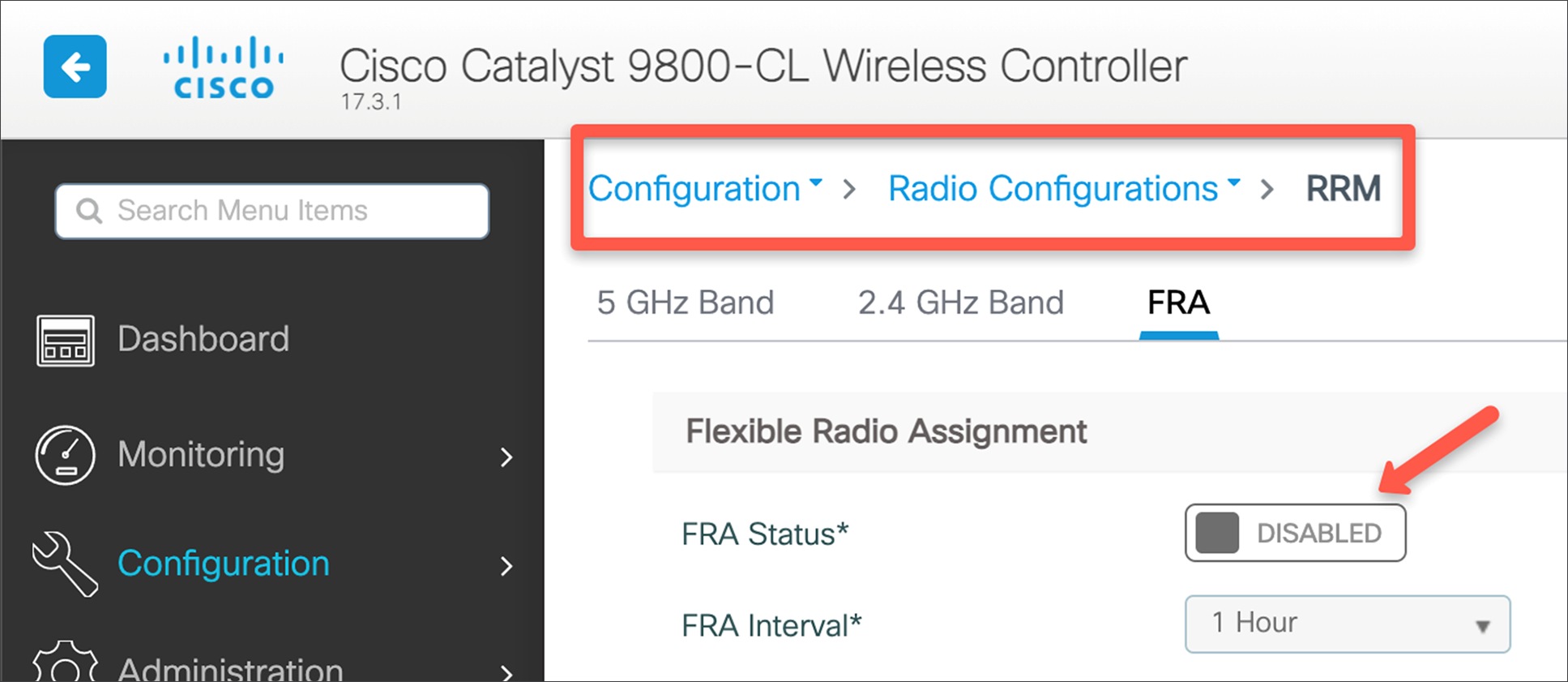
Disabling FRA in Cisco IOS XE