Renewable Generation Wind Farm
Available Languages
Bias-Free Language
The documentation set for this product strives to use bias-free language. For the purposes of this documentation set, bias-free is defined as language that does not imply discrimination based on age, disability, gender, racial identity, ethnic identity, sexual orientation, socioeconomic status, and intersectionality. Exceptions may be present in the documentation due to language that is hardcoded in the user interfaces of the product software, language used based on RFP documentation, or language that is used by a referenced third-party product. Learn more about how Cisco is using Inclusive Language.
Renewable energy is becoming a more popular method to generate energy with a much smaller impact on the global environment. Wind power is one of the most prevalent renewable energy forms and is gaining popularity globally.
To date Europe has led the way on harnessing wind power in building both onshore and offshore wind farms. Europe has been a progressive leader, and wind farms are now a major source of power in many European countries. However, China now leads the world in the amount of installed wind power. Recently both the U.S. and South Korea have accelerated their wind installations and planned developments.
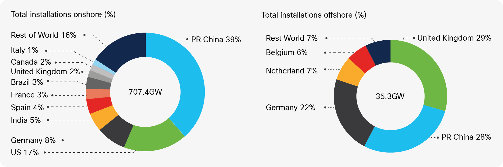
Source: GWEC Global Wind Report 2021
Wind turbine manufacturers are building larger and larger turbines. The cost of wind power generated is quite often cheaper than that produced by coal or gas plants. For many countries, wind power now makes up a sizable proportion of the generated energy mix.
Wind farm owners sell the power generated from wind farms to other public utilities under long-term (typically 20 years) Power Purchase Agreements (PPAs), through which they receive a fixed or annually adjusted price for the electricity. Renewable energy incentives (which vary by country) also play a role in the revenue stream of a managing owner.
The desire and commitments made to meet the global emissions reduction targets will drive growth moving forwards. New regions are highlighted for growth; for example, countries such as Chile, Colombia, Saudi Arabia, and Vietnam have plans for rapid growth.
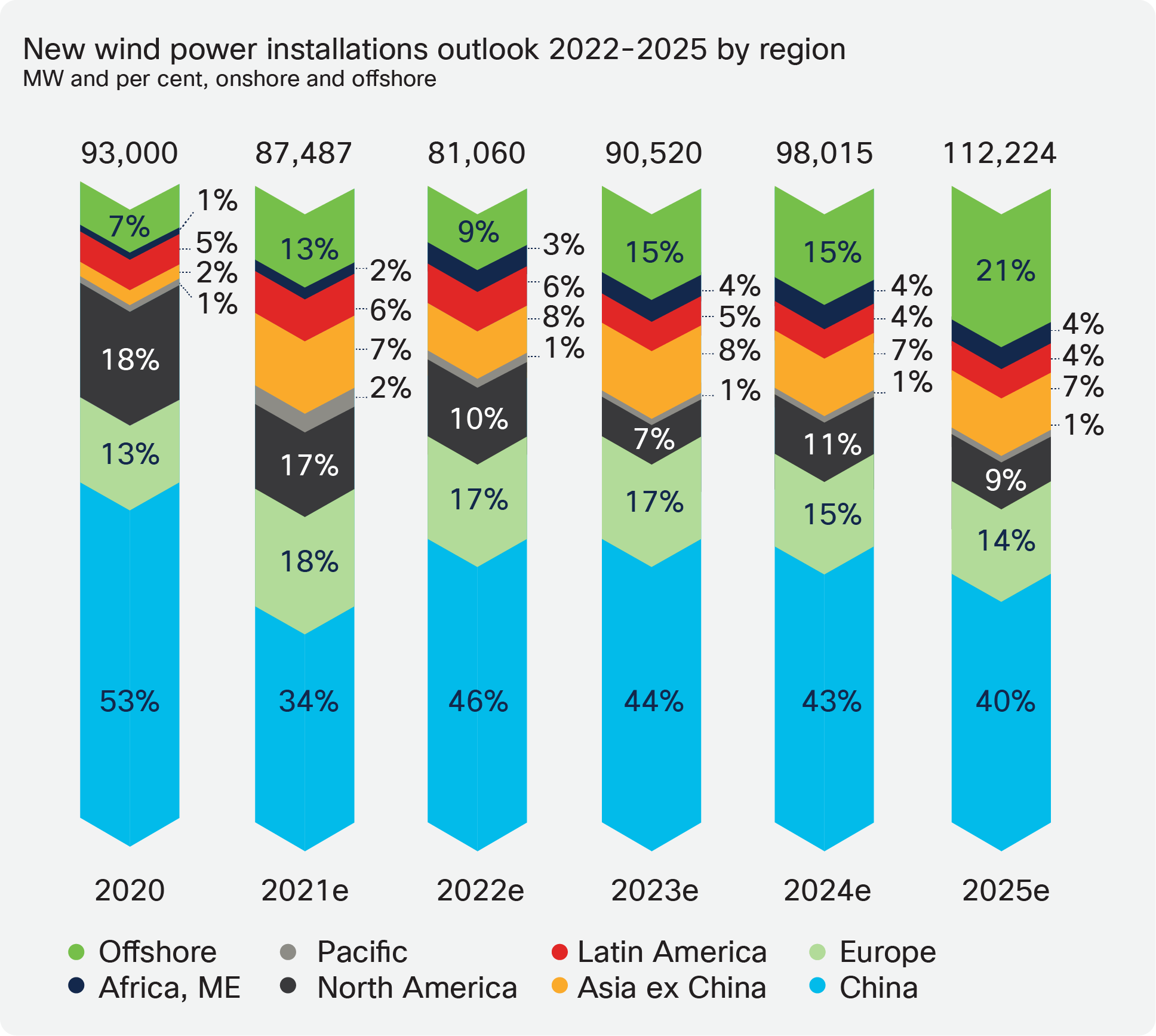
Source: GWEC Global Wind Report 2021
Renewable energy is a complex landscape of interested companies. In recent times, there has been a trend toward public utilities and more traditional fossil fuel companies (oil and gas) owning and operating both onshore and offshore wind farms.
These parties are also supported by large financing and equity partners.
Wind Farm Operator (Asset Operator)
Responsible for the daily operations and administration of the wind farm as a power- producing entity. Many operators are also involved in the development, ownership, and construction of the farm.
They sell the power produced to public utilities normally with long-term fixed price contracts in place.
Wind Farm Owner (Asset Owner)
Normally a consortium of parties such as public utilities or oil and gas companies and financing companies. There are also dedicated renewable energy companies and others who invest in this area.
It is also common to find wind farm owner/operators. Many such companies are dedicated renewable companies or renewable energy branches of traditional utilities or oil and gas companies.
WTG Supplier
Wind turbine manufacturers design, test, and manufacture wind turbine equipment including wind turbine generators (WTGs) and ancillary systems (such as Supervisory Control and Data Acquisition [SCADA], power automation).
These suppliers (Vestas, Siemens, and GE being the largest) also provide support and maintenance services (O&M) on an ongoing basis for many wind farm operators. It is typical for the monitoring and maintenance of the wind turbine network to be outsourced to these same manufacturers.
OFTO
OFTO refers to the Offshore Transmission Owner. Offshore wind farms are connected to the onshore grid by way of an “export” cable. Regulatory requirements in many countries prohibit power generators from owning transmission assets. Thus the export cable will be owned and operated by another third party.
Developers, who will often also be the wind farm owner/operator, will divest the export cable system to a third party by way of a regulated auction.
Grid Utility
The traditional power grid operator providing the connection point for the exported power from the wind farm can be either a Transmission System Operator (TSO) or Distribution Network/System Operator (DSO/DNO).
Public utilities that are also wind farm owners separate the grid and renewable business usually due to strict regulatory requirements.
Multiple Operating Parties
The multiple parties involved also presents challenges for network operation and access to the required services. The parties involved could be as diverse as the wind farm operator staff, turbine network operation and maintenance (O&M) engineers, substation engineers, and various supplier subcontractors.
All these require network access but have differing needs on what equipment or systems to be accessed.
Environment
Wind farms are challenging environments in relation to communication networks.
● Remote and distributed locations
◦ Wind farms are located in areas that are generally underserved by traditional communications networks. A typical operator will have multiple farms distributed regionally or even globally. Each operator will have challenges with WAN connectivity to the sites and connectivity within the site itself.
● Offshore locations
◦ These provide a unique set of challenges from the environmental aspect (weather, salt, spray etc.) to the ease of access for maintenance personnel.
● Onshore locations
◦ While not as challenging as offshore locations, onshore farms are normally in remote areas where readily available communication networks are not available.
● Data/Control Centers
◦ Every operator will have a number of data centers that serve the business. These will provide many of the services that are required to be accessed on the wind farm. Connectivity from these data centers via the WAN to each wind farm is required.
A basic wind farm schematic is shown below, illustrating the wind farm and the components upstream.
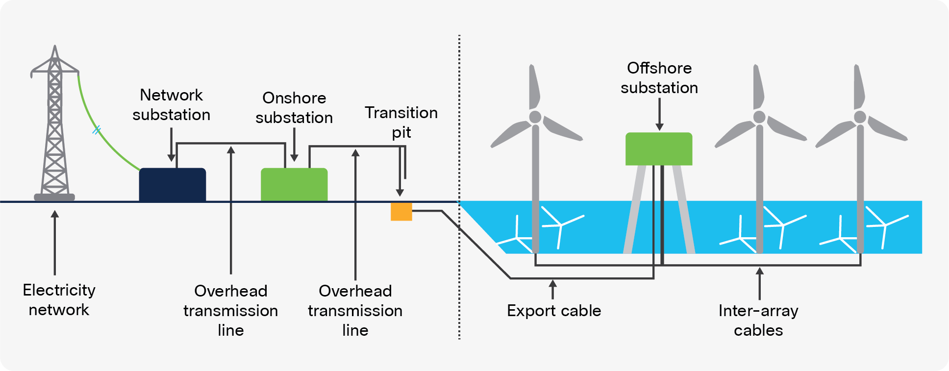
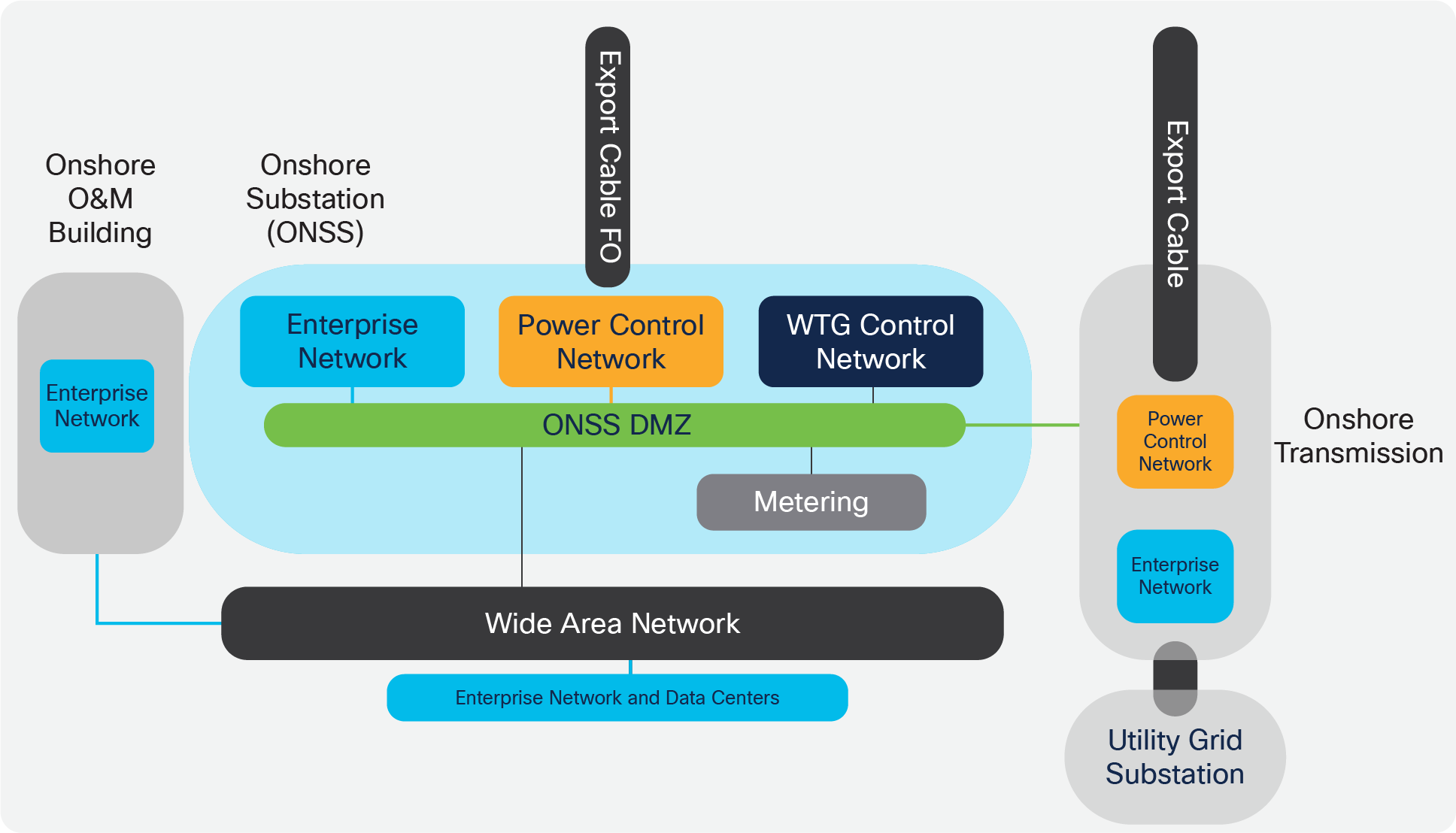
Onshore Wind Farm Functional Building Blocks
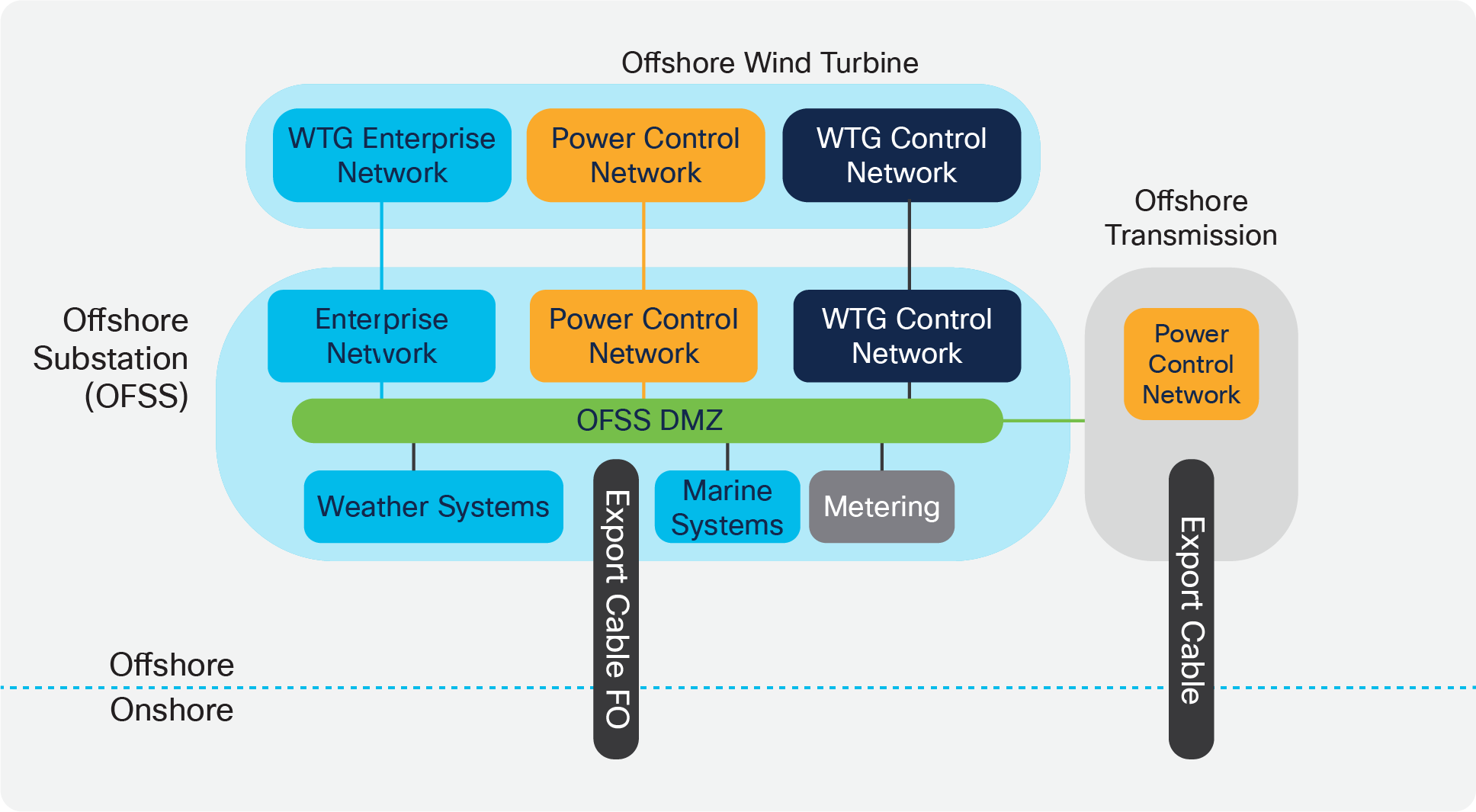
Offshore Wind Farm Functional Building Blocks
Remote Access
There is a need for suppliers and operations staff to be able to access the farm remotely. Remote access must be provided in a secure fashion with no separate dedicated “back door” or local connections.
Control of who is authorized to access the network and what they can access should be controlled in a managed fashion.
The use of bastion hosts or jump servers is recommended to restrict users to using applications authorised by the asset owner.
Both external vendors/contractors and internal enterprise users should use the same method to access industrial assets within the onshore and offshore networks.
External users should be authenticated (using two-factor authentication) via the enterprise remote access infrastructure to be given access to reach the bastion hosts only.
Remote access should provide full logging and auditing capabilities.
Automation
The need exists for a more cost-effective operational model, especially around easier deployment, maintenance, and troubleshooting plus improving stability and the resiliency of wind farm operations.
Traditionally engineering the communications network is a manual task, with equipment being configured by command-line interface (CLI). With the explosion of facilities being built and the lack of skilled staff, automation becomes a major consideration for deploying and managing the lifecycle of any underlying networks (WAN and wind farm networks).
The ability to remove costly deployment errors (especially offshore which have a high cost to remedy) and create repeatable templated system configurations will ease the burden of creating these complex networks.
Cybersecurity
Many wind farms increasingly form part of a country’s national critical infrastructure and as such should be protected.
Cybersecurity must be comprehensive and a fully integrated part of the overall end-to-end design. Any design should seek to minimize any administrative overhead in cybersecurity deployment and operations.
Having the capability to identify all wind farm assets and their associated vulnerabilities, detect any new threats or anomalous behavior on the network, and monitor traffic on an ongoing basis will greatly enhance the capability to do this.
Improved security measures are necessary to become compliant with the North American Electric Reliability Corporation Critical Infrastructure Protection requirements (NERC CIP).
The following fundamental principles must be adopted by the asset network operator to ensure secure systems:
● Visibility of all devices in the wind farm plant networks. Traditionally, enterprise devices such as laptops, mobile phones, printers, and scanners were identified by the enterprise management systems when these devices accessed the network. This visibility can be extended to all devices on the plant networks.
● Segmentation and zoning of the network. Segmentation is a process of bounding the reachability of a device, and zoning is defining a layer where all the members in that zone will have identical security functions. Providing zones in a network provides an organized way of managing access within and across the zone. Segmenting the devices further reduces the risk of spread of an infection when a device gets subjected to malware.
● Identification and restricted data flow. All the devices in the wind farm plant (OT) and enterprise (IT-managed) must be identified, authenticated, and authorized. The network must enforce a policy when the users and Industrial Automation and Control System (IACS) assets attach to the network.
● Network anomalies. Any unusual behavior in network activity must be detected and examined to determine if the change is intended or due to a malfunction of the device. Detecting network anomalies as soon as possible gives plant operations the means to remediate an abnormality in the network sooner, which can help to reduce possible downtimes.
● Malware detection and mitigation. The unusual behavior displayed by an infected device must be detected immediately, and the security tools should allow a remediate action to the infected device.
● Traditional firewalls are not typically built for industrial environments. There is a need for an industrial firewall that can perform deep packet inspection on industrial protocols to identify anomalies in IACS traffic flow.
● Hardening of the networking assets and infrastructure in the plant networks is a critical consideration. This includes securing key management and control protocols such as Simple Network Management Protocols (SNMP) among others.
● Automation and control protocols. It is also important to monitor the IACS protocols themselves for anomalies and abuse.
● Adhering to the security standards. In the 1990s, the Purdue Reference Model and ISA 95 created a strong emphasis on architecture using segmented levels between various parts of the control system. This was further developed in ISA99 and IEC 62443, which brought focus to risk assessment and process. The security risk assessment will identify which systems are defined as critical control systems, non-critical control systems, and non-control systems.
Industry Standards and Regulations
Standards and guidelines are an essential foundation, but they do not prescribe how to secure and design specific systems. As all systems are different, standards and guidelines should be leveraged as a best practice framework and specifically tailored to business needs. In this section, a few of the industry standards are briefly described and limited to those that are both generally applicable and generally applied.
ISA-95/PERA (Purdue)
ISA-95 and PERA provide a general architecture for all types of IACS, providing not only common nomenclature but also common building blocks. More details can be found at:
● ISA-95 web site
https://isa-95.com/
● PERA web site
http://www.pera.net/
IEC 62443/ISA-99
The IEC 62443 series builds on established standards for the security of general-purpose IT systems (for example, the ISO/IEC 27000 series), identifying and addressing the important differences present in an industrial control system (ICS). Many of these differences are based on the reality that cybersecurity risks within an ICS may have health, safety, or environment (HSE) implications, and that the response should be integrated with other existing risk management practices addressing these risks.
NIST Cybersecurity Framework
The National Institute of Standards and Technology (NIST) Cybersecurity Framework (https://www.nist.gov/cyberframework) is a Best Practices guideline, not a requirements standard. The genesis of the NIST Cybersecurity Framework came from the 2014 changes to the National Institute of Standards and Technology Act, which was amended to add “...on an ongoing basis, facilitate and support the development of a voluntary, consensus-based, industry-led set of standards, guidelines, best practices, methodologies, procedures, and processes to cost-effectively reduce cyber risks to critical infrastructure.”
NIST 800 Series
The NIST 800 Series, as it is commonly called, is a set of documents from NIST covering U.S. government security policies, procedures, and guidelines. Although NIST is a U.S. government unit (under the Commerce Department), these guidelines are referenced and indeed mandated by not only the U.S. government but by many governments and corporations around the world—even those not directly involved in the public sector. Regarding this Cisco Validated Design and any associated Cisco Validated Designs, the subset called NIST SP 800-82 “Guide to Industrial Control Systems Security” is of particular importance as it is specifically targeted at the IACS space.
The purpose of this document is to provide guidance for securing ICS, including SCADA systems, distributed control systems (DCS), and other systems performing control functions. The document provides a notional overview of ICS, reviews typical system topologies and architectures, identifies known threats and vulnerabilities to these systems, and provides recommended security countermeasures to mitigate the associated risks. Additionally, it presents an ICS-tailored security control overlay, based on NIST SP 800-53 Rev. 4 [22], to provide a customization of controls as they apply to the unique characteristics of the ICS domain.
NERC CIP
NERC CIP, the North American Electric Reliability Corporation (NERC) Critical Infrastructure Protection (CIP), is utility specific in origin as the name implies, However it is widely referenced and adopted outside of the utility space. Also as its name implies, it targets critical infrastructure protection, which is a widely used term and the subject of many standards, guidelines, and best practices (see https://en.wikipedia.org/wiki/Critical_infrastructure_protection for more details). NERC CIP in particular is used in this CVD and the associated CVDs primarily because it was developed around the particulars of the IACS infrastructure. Therefore it is highly relevant to the subject at hand as well utilizing much of the same terminology.
IEEE 1588 Precise Time Protocol
Defined in IEEE1588 as Precision Clock Synchronization for Networked Measurements and Control Systems, Precise Time Protocol was developed to synchronize the clocks in packet-based networks that include distributed device clocks of varying precision and stability. Precise Time Protocol (PTP) is designed specifically for industrial, networked measurement and control systems, and is optimal for use in distributed systems because it requires minimal bandwidth and little processing overhead. PTP facilitates services that require extremely precise time accuracy and stability such as peak-hour billing, virtual power generators, outage monitoring and management, and so on.
PTP was originally developed in 2002. It was enhanced in 2008 (IEEE 1588-2008) and is referred to as PTPv2. This version establishes the basic concept and algorithms for distribution of precise time. These basics have been adopted into “profiles” that are specific definitions for distribution of time designed for particular use cases. The following PTP profiles are:
● Default Profile: This profile was defined by the IEEE 1588 working group. It has been adopted in many industrial applications, including by the ODVA.org (Open DeviceNet Vendors Association) in the Common Industrial Profile (CIP) as CIP Sync services. This solution supports the default profile in the Sitewide Precise Time Distribution feature. As well, the Rockwell Automation and Cisco® Converged Plantwide Ethernet (CpwE) solution supports the default profile in the Deploying Scalable Time distribution within a Converged Plantwide Ethernet Architecture ( https://www.cisco.com/c/en/us/td/docs/solutions/Verticals/CpwE/5-1/STD/DIG/CpwE-5-1-STD-DIG.html).
● Power Profile: This profile was defined by the International Electro technical Commission (IEC) standard 62439. The power profile is used in the IEC 61850 standard for communication protocol for substation automation. This profile is supported in the Cisco Substation Automation Local Area Network and Security CVD (https://www.cisco.com/c/en/us/td/docs/solutions/Verticals/Utilities/SA/2-3-2/CU-2-3-2-DIG.html) .
● Telecom Profile: The International Telecommunication Union’s Telecommunications Standards (ITU-T) group has established a set of PTP profiles for the telecom industries. A variety of Cisco products support these profiles but are not commonly used in industrial automation. This profile is not supported in this solution.
● IEEE 802.1 AS profile: The IEEE created the Timing and Synchronization for Time-Sensitive Applications at this profile as part of the Audio-Visual Bridging (AVB) set of technical standards. This profile is being enhanced for the industrial ecosystem driven Time-Sensitive Networks (TSN) set of technical standards under the IEEE 802.1AS-Rev working group. Some Cisco products support 802.1AS for AVB and TSN applications. This solution does not support 802.1AS at this time.
Cisco provides a comprehensive portfolio including routing, switching, wireless, collaboration, data center, IoT, and security. Whatever a customer’s goals might be, Cisco is able to offer a trusted end-to-end solution that combines our portfolio with technologies from a robust ecosystem of partners. Cisco’s Intent-Based Networking (IBN) technology transforms hardware-centric, manually configured networks into controller-led networks that capture network managers’ business intent. These controller-led networks use automation to translate intent into policies that are applied consistently across the network and monitored comprehensively to help ensure proper ongoing operation at scale. Some of the world’s largest and most vital networks have embraced Cisco IBN because it brings new levels of network performance, security, and reliability to the network at larger scale, and with less effort.
Network security should be prioritized from day one and not as an afterthought. An effective cybersecurity strategy requires a comprehensive, systematic, coordinated approach to protect against a broad and continuously evolving set of threats. Cisco offers an ever-expanding, industry-leading portfolio of cybersecurity products to provide comprehensive protection for IT and operations networks. Cisco’s portfolio includes Cisco Cyber Vision, which provides visibility into industrial devices and data traffic flows; Secure Network Analytics (formerly Cisco Stealthwatch®), which can monitor data flows and detect traffic anomalies that can be used to enhance network segmentation policies; a policy platform called Cisco Identity Services Engine (ISE), which helps define and manage user profiles and access policies at scale; Cisco Malware Defense (formerly Cisco Advanced Malware Protection) to provide up-to-date monitoring and detection of malware threats; Cisco Umbrella® to prevent passengers or workers from accessing malicious network domains; and Cisco DNA Center™ and SD-Access to automate and simplify security policy implementation and assurance across all network devices. Additionally, Cisco SecureX™ provides a consolidated view for simplified management of the overall security approach.
| Use Case |
Type of Services |
Areas of the Network |
| WTG SCADA |
Turbine telemetry |
Telemetry data collection associated with the turbine system a and components |
| Fire detection |
Detection of smoke and fire within the turbine |
|
| Turbine ancillary systems |
Telemetry data collection associated with the ancillary systems (e.g., elevator, nav lights) |
|
| Weather systems |
Data from weather-related systems (such as radar for offshore farms, wind speed anemometers) |
|
| Power Automation and Control |
Turbine transformer/IED/switchgear |
Monitoring and control of transformer, switchgear, and intelligent electronic devices (IEDs) within the turbine |
| Export cable systems |
Monitoring and control of the export cable systems for offshore wind farms. Normally a separate self-contained HVDC/AC system |
|
| Offshore/onshore substation |
Monitoring and control of substation elements such as breakers, IEDs, and other equipment used within the onshore and offshore substations |
|
| Process and Control Systems |
Heating and ventilation systems |
Heating and ventilation systems |
| Public Announcement and General Alarm (PAGA) Systems |
Audio systems for announcements and alarms |
|
| Backup generators |
Generators for emergency power |
|
| Fire detection systems |
Detection of fire |
|
| Marine-Related Systems |
Tetra, VHF, UHF Radio |
Ship and worker radio systems |
| Automatic identification system (AIS) |
Shipping identification system |
|
| Radar systems |
Radar for offshore vessel management |
|
| Enterprise Services |
IP telephony |
Enterprise voice communications for workers Fixed and mobile handsets (Wi-Fi) |
| Corporate network access |
General network access for enterprise services such as email, file sharing, video, and web |
|
| Guest network access |
Basic internet access for subcontractors |
|
| Physical Security |
Closed Circuit Television (CCTV) |
Physical security monitoring of turbine assets and areas around turbines for safety and security |
| Access control |
Intrusion detection and entry into areas such as O&M offices and turbine towers |
|
| Misc. Systems |
Bat and bird monitors |
Detection of protected wildlife |
| Radar |
Additional radar equipment as specified by certain bodies (military, Coast Guard etc.) |
|
| Additional Use Cases: |
||
| Vessel Connectivity |
IP telephony |
Enterprise voice communications for workers Fixed and mobile handsets |
| Wireless network access (Wi-Fi) |
Wi-Fi access points within operations vessels to provide enterprise network access for staff and to provide IP telephony coverage |
|
| Environmental Sensors |
Heat and humidity |
Turbine nacelle or tower and external measurements |
| Door open and close |
Turbine tower, external ancillary cabinets |
|
| Machine temperature |
Machine casing or transformer case temperature |
|
| Location-Based Services |
Personnel location and Man Down (for lone worker) |
Wi-Fi access points providing Bluetooth capability for short-range personnel devices for location and Man Down worker safety use cases |
Out-of-Band Connectivity during Construction Phases
Turbine suppliers need out-of-band connectivity to each turbine for commissioning or monitoring during the construction phase when no inter-turbine cabling is present (i.e., no remote access is possible) or physical access to the wind turbine is not possible (construction activities or weather).
Access to each turbine to configure and test equipment can negate the need for costly site visits reducing the costs and safety aspect for many wind farm suppliers.
With IOT Operations Dashboard and an IR1101 using cellular connectivity (where available), a remote connection can be provided to each turbine for the duration of the construction phase. An Internet Protocol Security (IPsec) tunnel is utilized to encrypt all traffic between the wind turbine and the vendor site.
This solution utilizes public cellular network backhaul but can also use private cellular networks where available. Thus it is suitable for onshore or offshore sites with cellular coverage.
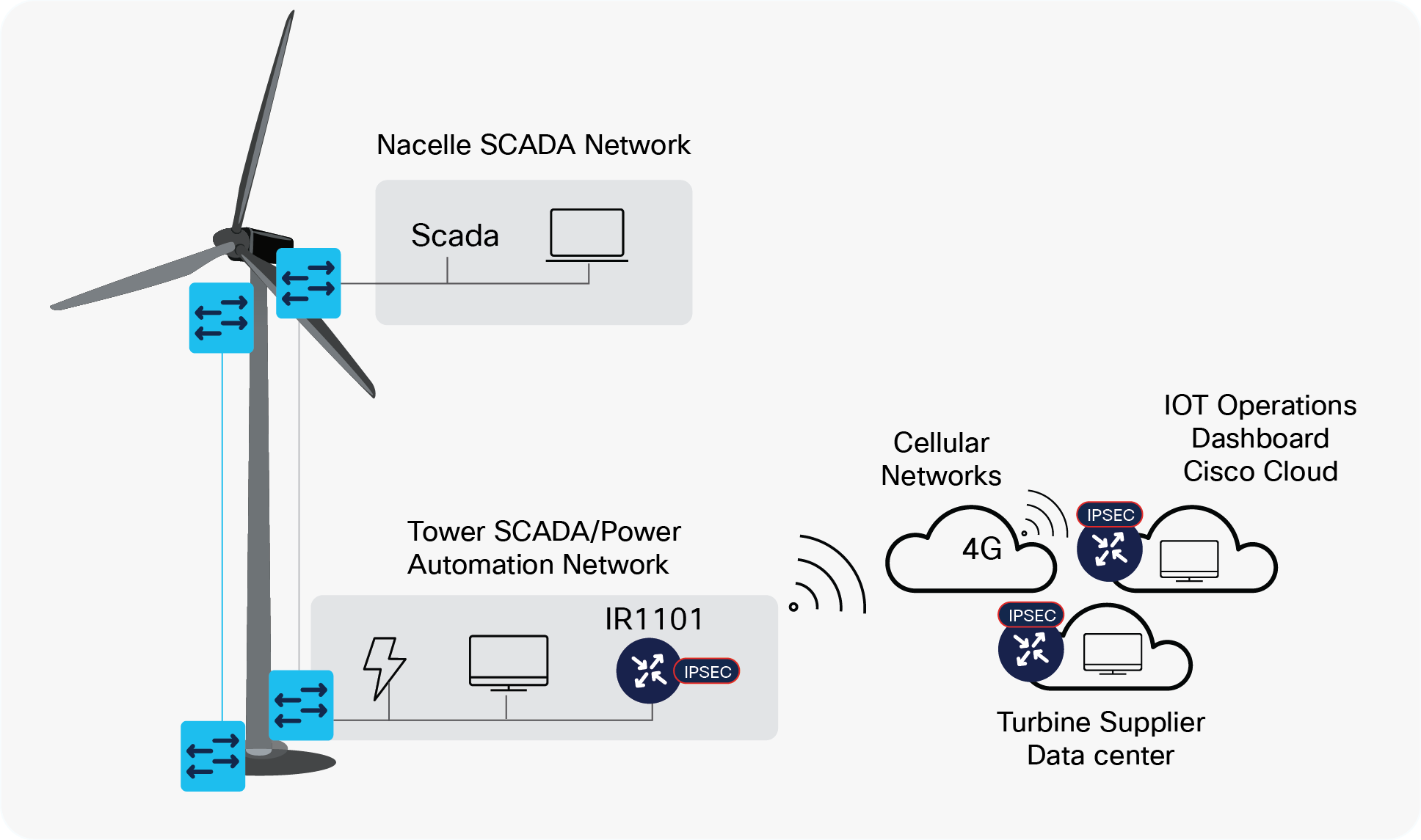
Temporary Remote Access to Turbine during Construction Phase
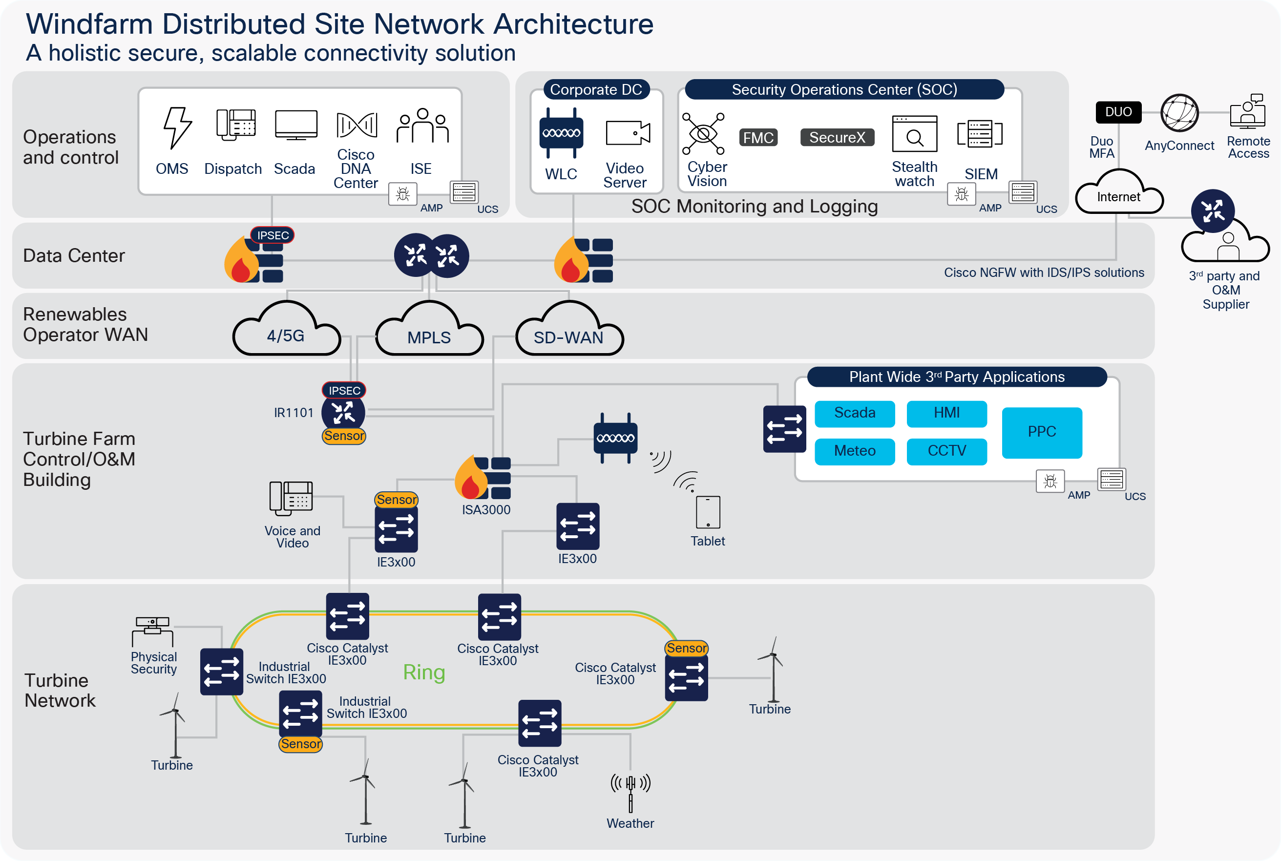
Small Wind Farm Sites
Many operators also manage small turbine sites usually onshore, ranging from a few turbines to tens of turbines. These sites require a more cost-effective and light-weight solution for connecting the site to the Operator WAN (Cellular, MPLS and/or SDWAN) and centralised data centers.
Therefore a more condensed solution is required utilising the following components:
● Cisco Catalyst IR1101 Ruggedised Router
● Cisco Catalyst IE3x00 Ruggedised switches
● Cisco ISA3000 Industrial Firewall
● Optional onsite plant compute using Cisco UCS servers
The diagram below depiects a typical small windfarm site with less onsite infrastructure.
Future consideration to condense the solution further based on feature roadmap timelines should consider:
● Cisco Catalyst IR1835 Ruggedised Router
◦ Cisco SDWAN solution for WAN automation
◦ Cisco Unified Threat Defense for IDS and URL Filtering
● Cisco Catalyst IE 3x00 switching for port fanout and POE support.
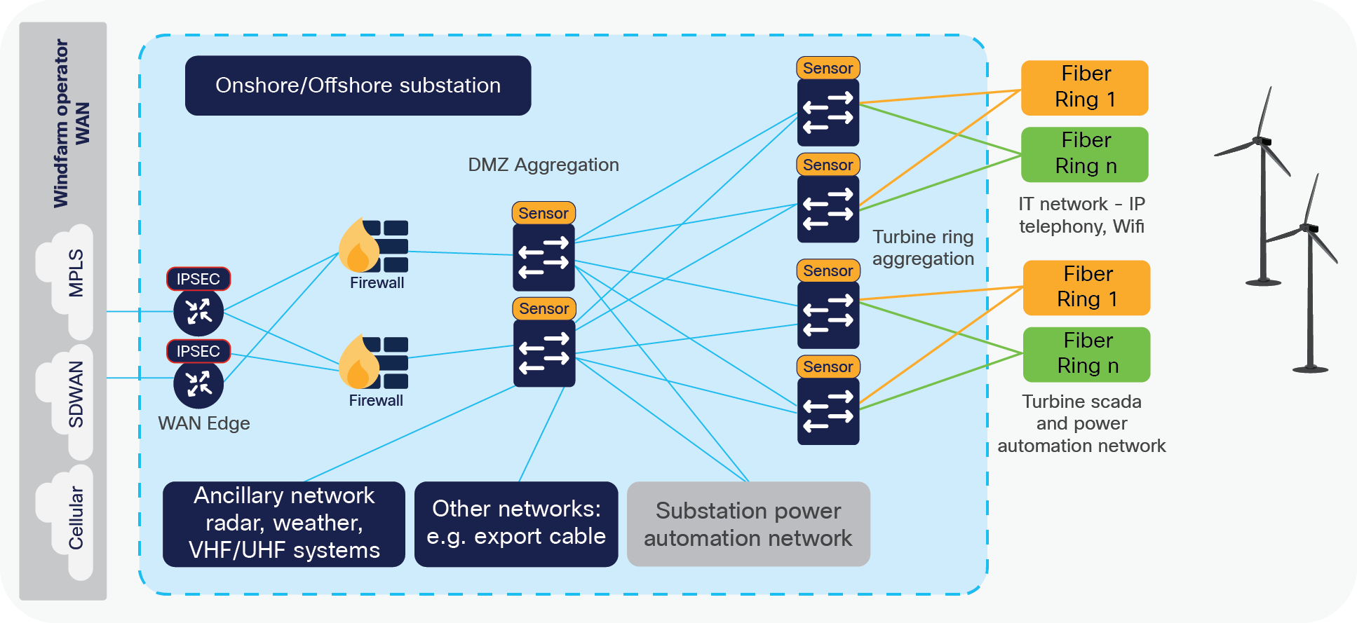
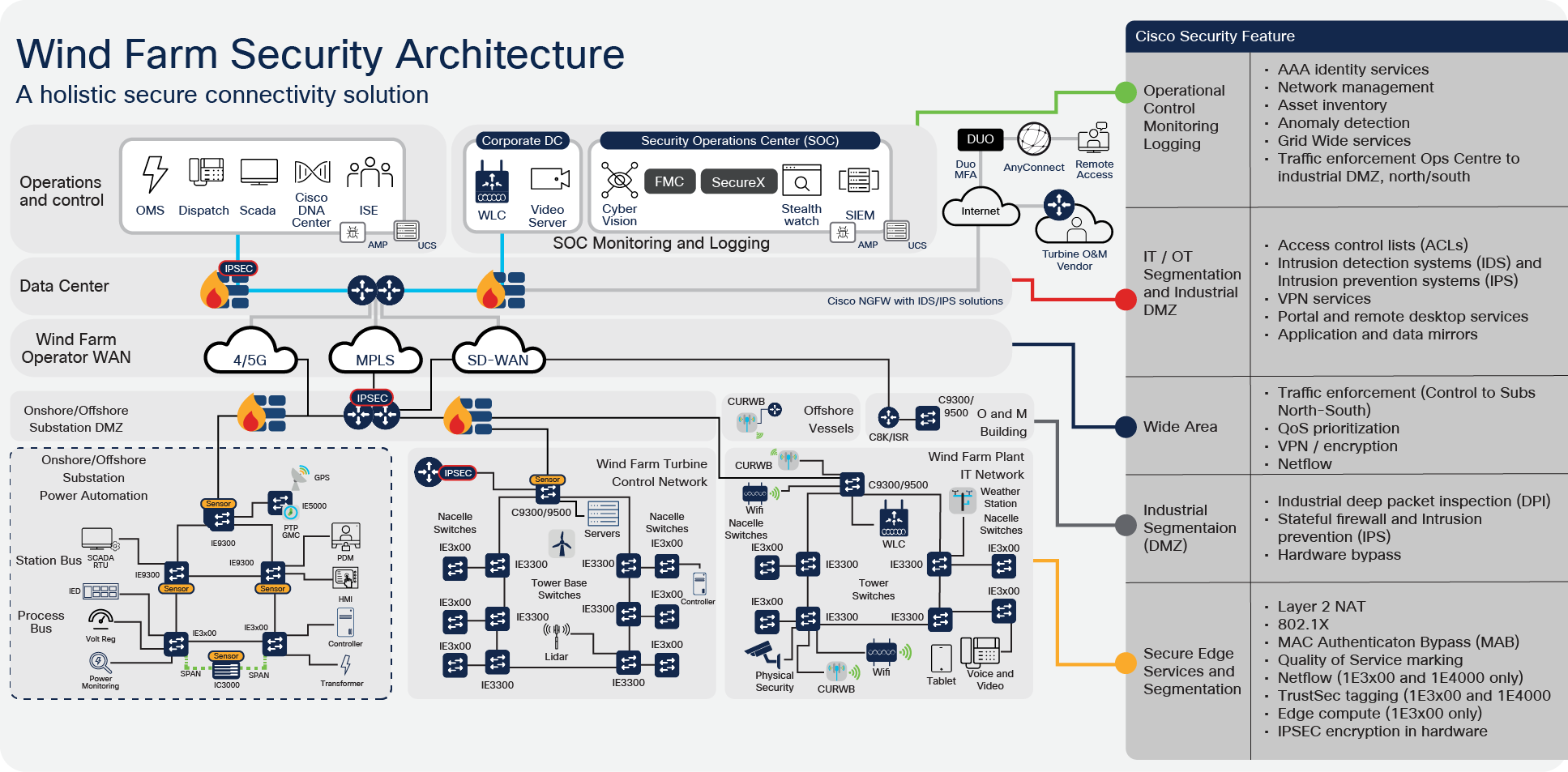
Wind Farm Reference Architecture
The end-to-end reference architecture provides a modular approach to support IT, turbine, and substation use cases for both onshore and offshore wind farms. Flexibility is provided to allow different partners to be responsible for operating and maintaining the various parts of a wind farm.
Not shown here is the export cable for offshore connectivity. This is illustrated in a later section of the document.
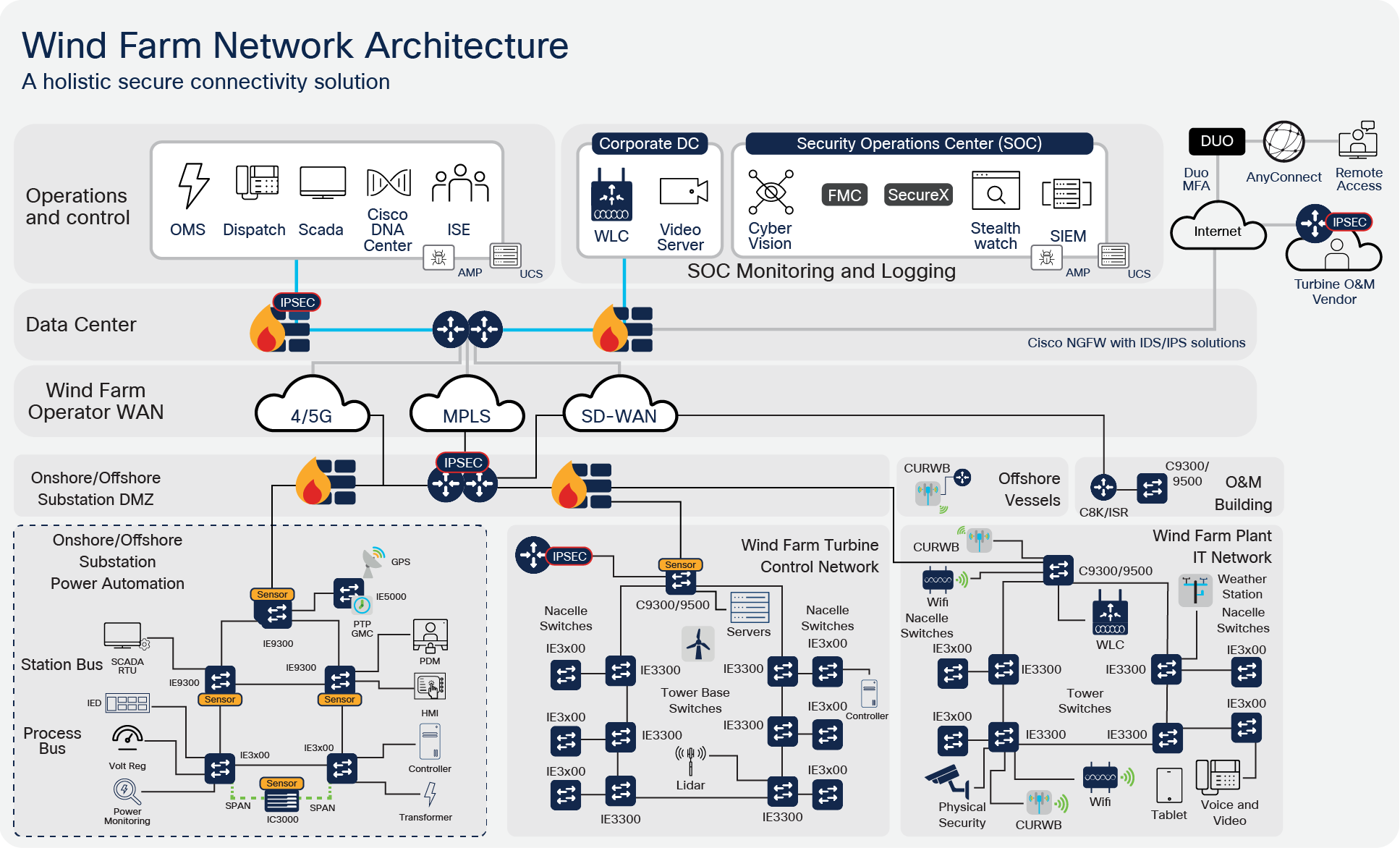
Primary building blocks within the architecture are:
● Wind Farm operator datacenter
● Wind Farm Wide Area Network (WAN)
● Onshore DMZ
● Onshore Substation
● Offshore DMZ
● Offshore Substation
● Turbine Control Network (i.e SCADA)
● Turbine Power Automation and Control Network
● Turbine Plant IT Network (i.e. Enterprise and Plant services)
● Offshore Service operations vessels (SOV)
● Operations and Maintenance buildings (O&M)
Wide Area Network
Connectivity to wind farms can be challenging due to the locations they are sited (either onshore in remote areas, or offshore).
Various traditional technologies used today, including public cellular, service provider Multiprotocol Label Switching (MPLS), and leased lines utilizing microwave radio, have their limitations. These limitations are more pronounced in the case of wind farms spread across numerous global locations where no single public network provider is possible.
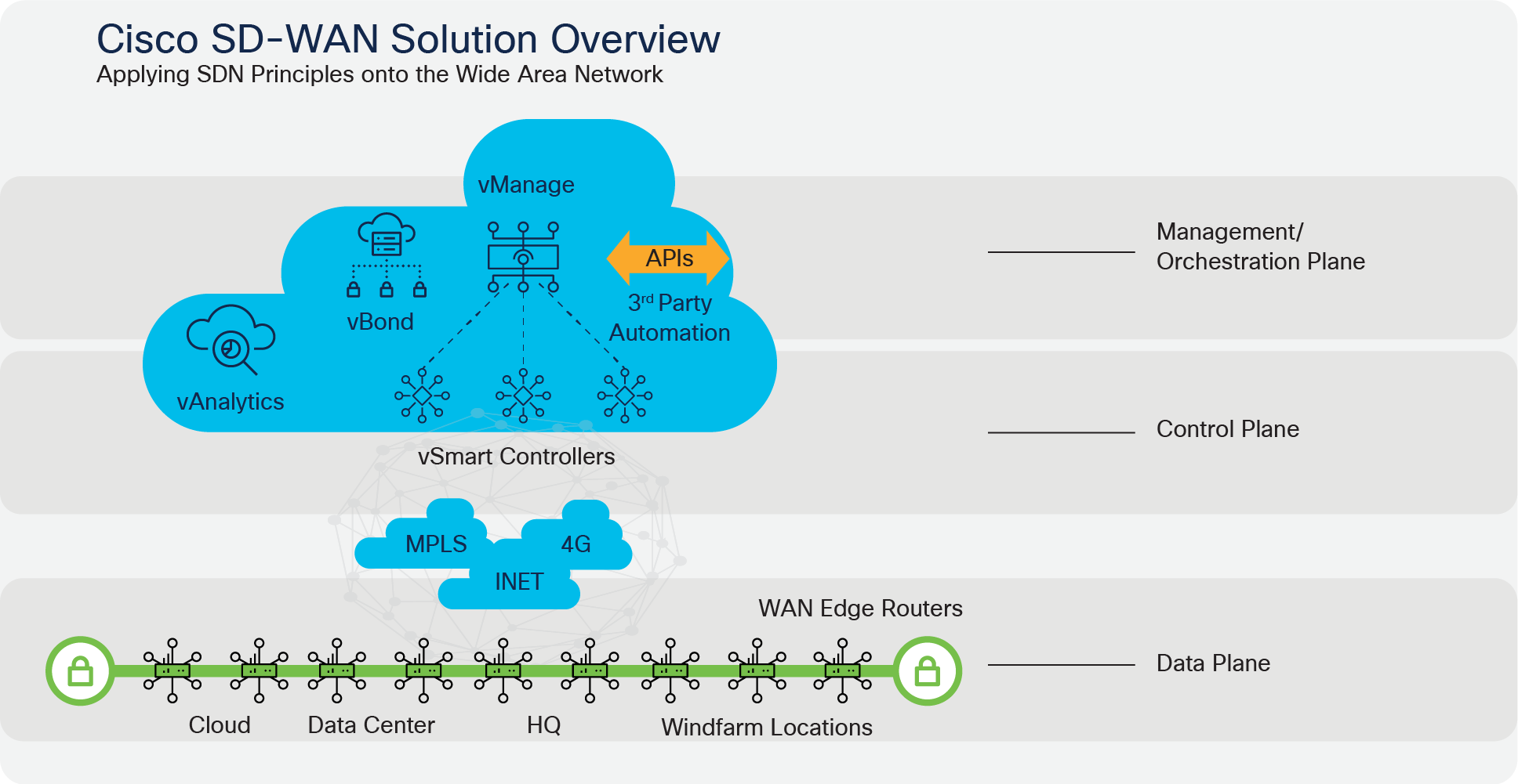
SD-WAN is part of a broader technology of software-defined networking (SDN). SDN is a centralized approach to network management that abstracts away the underlying network infrastructure from its applications. This de-coupling of data plane forwarding and control plane enables you to centralize the intelligence of the network and allows for more network automation, operations simplification, and centralized provisioning, monitoring, and troubleshooting. SD-WAN applies these principles of SDN to the WAN.
SD-WAN enables wind farm operators to use their own IP addressing schemes and create VPNs as needed to segregate the various types of traffic.
The Cisco SD-WAN solution is an enterprise-grade WAN architecture overlay that enables digital and cloud transformation for enterprises. It fully integrates routing, security, centralized policy, and orchestration into large-scale networks. It is multitenant, cloud-delivered, highly automated, secure, scalable, and application-aware with rich analytics. The Cisco SD-WAN technology addresses the problems and challenges of common WAN deployments. Some of the benefits include:
● Centralized network and policy management, as well as operational simplicity, resulting in reduced change control and deployment times
● A mix of MPLS and low-cost broadband or any combination of transports in an active/active fashion, optimizing capacity and reducing bandwidth costs
● A transport-independent overlay that extends to the data center, branch, and cloud
● Deployment flexibility. Due to the separation of the control plane and data plane, controllers can be deployed on premises or in the cloud. Cisco WAN Edge router deployment can be physical or virtual and can be deployed anywhere in the network.
● Robust and comprehensive security, which includes strong encryption of data, end-to-end network segmentation, router, and controller certificate identity with a Zero Trust security model, control plane protection, application firewall, and insertion of Cisco Umbrella, firewalls, and other network services
● Seamless connectivity to the public cloud and movement of the WAN edge to the branch
● Application visibility and recognition in addition to application-aware policies with real-time service-level agreement (SLA) enforcement
● Dynamic optimization of SaaS applications, resulting in improved application performance for users
● Rich analytics with visibility into applications and infrastructure, which enables rapid troubleshooting and assists in forecasting and analysis for effective resource planning
The following are some of the capabilities SD-WAN can provide:
● Automated Zero Touch provisioning: The ability to remotely provision a router anywhere in the WAN by just connecting it with a cable to the transport network and powering it on. The WAN Edge router discovers its controllers automatically and fully authenticates to them, and then automatically downloads its prepared configuration before proceeding to establish IPsec tunnels with the rest of the existing network. Automated provisioning helps to lower IT costs.
● Bandwidth augmentation: Enables customers to increase WAN bandwidth by leveraging all available WAN transports and routing capabilities to distribute traffic across available paths in an active/active fashion. Traffic can be offloaded from higher quality, more expensive circuits like MPLS to broadband circuits that can achieve the same availability and performance for a fraction of the cost. Application availability is maximized through performance monitoring and proactive rerouting around impairments.
● VPN segmentation: Traffic isolation is key to any security strategy. Traffic that enters the router is assigned to a VPN, which not only isolates user traffic, but also provides routing table isolation. This ensures that a user in one VPN cannot transmit data to another VPN unless explicitly configured to do so. When traffic is transmitted across the WAN, a label is inserted after the Encapsulating Security Payload (ESP) header to identify the VPN that the user’s traffic belongs to when it reaches the remote destination.
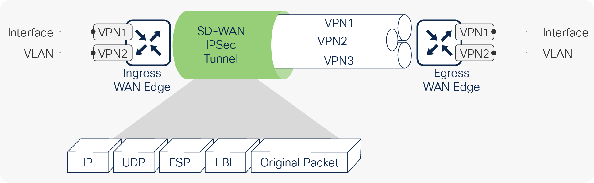
End-to-end segmentation
● Centralized management: vManage offers centralized fault, configuration, accounting, performance, and security management as a single pane of glass for Day 0, Day 1, and Day 2 operations. vManage offers operational simplicity and streamlines deployment by using ubiquitous policies and templates, resulting in reduced change control and deployment times.
Turbine Farm
Turbine
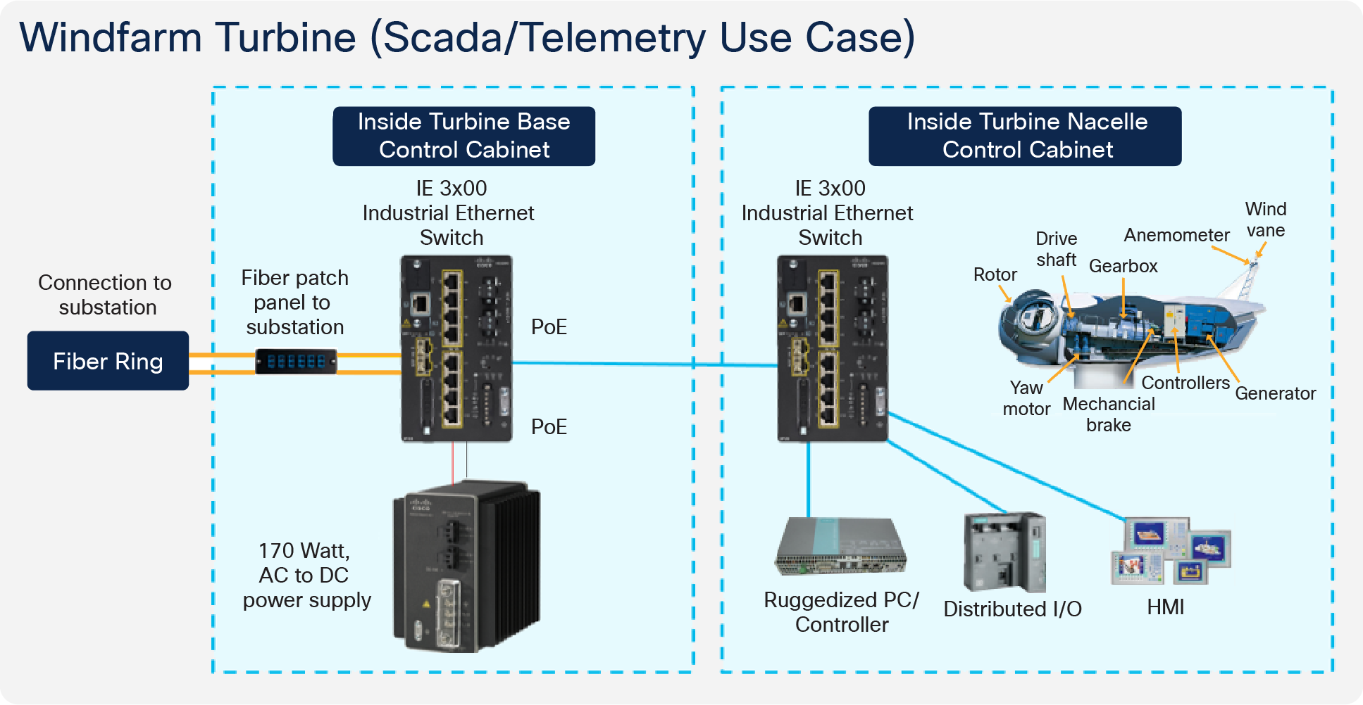
A wind turbine consists of two main areas:
● The nacelle that includes components such as the rotor, gearbox, generator, yaw motor, SCADA controllers, anemometer, mechanical brake, and other various mechanical components
● The tower that supports and provides access to the nacelle plus houses components such as electrical switchgear and inter-array cable termination
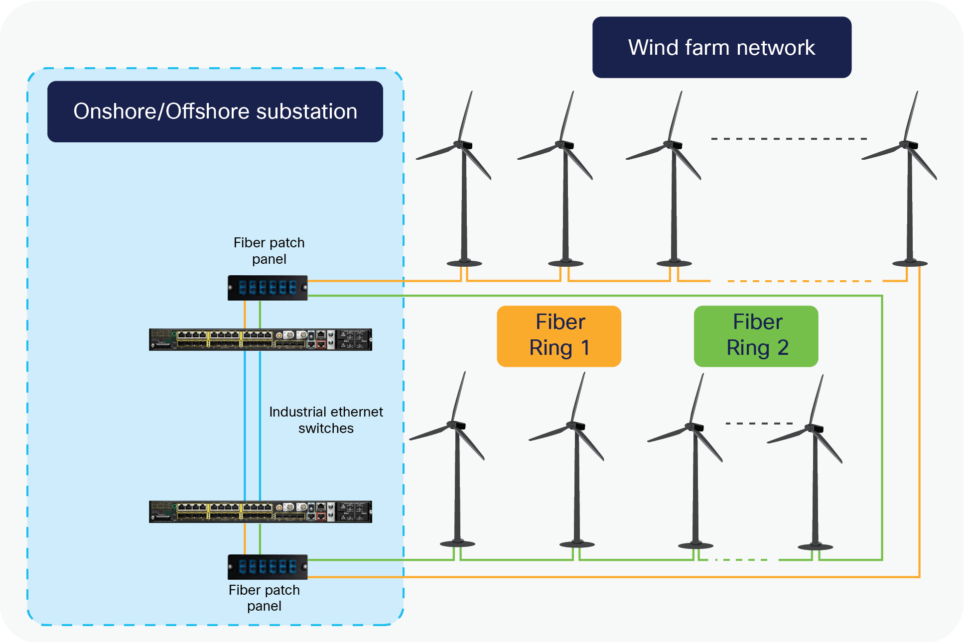
Each turbine requires two switches for the SCADA network, one for the nacelle and one for the tower.
The tower switch is usually connected as part of a ring with other tower switches, and the nacelle switch is a spur from the tower switch. The switches provide connectivity for local devices and systems (SCADA, power control and automation, CCTV, IP telephony, Wi-Fi access points etc). Segregation is provided by VLANs.
However, it is increasingly common for many wind farm operators to keep the turbine operation network (SCADA network) physically separate from the wind farm operator enterprise network (“Plant IT” network). This is often for contractual and commercial reasons with the turbine O&M responsible party, rather than for technical reasons.
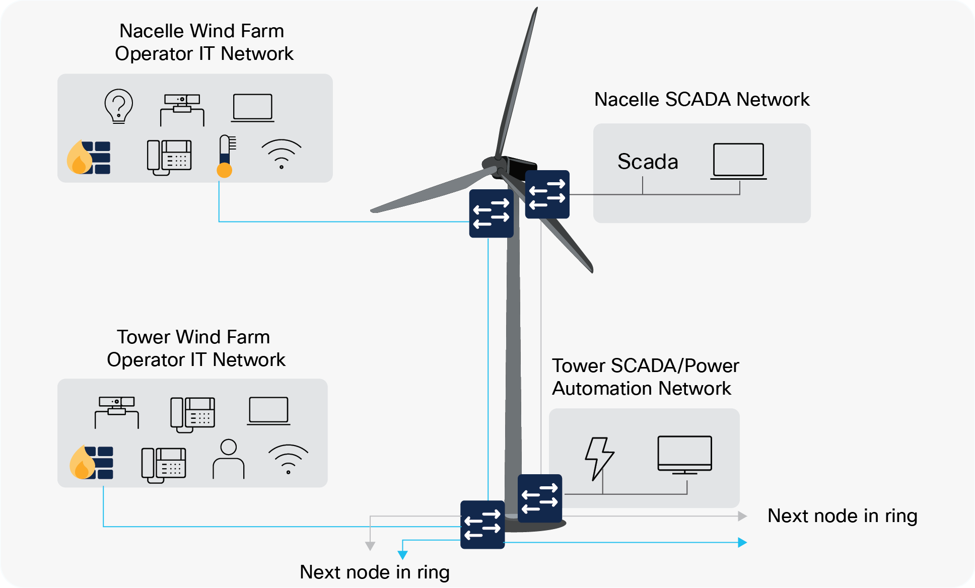
It is a common requirement for four switches in total in each turbine, all usually installed by the turbine supplier. Two are used by the Wind Farm Operator (Plant IT network) and two dedicated to the SCADA network for turbine O&M. Each pair of switches also connects via a separate inter-array fiber ring to maintain the separation within the wind farm network.
At a single turbine, the switches are not configured redundantly on a node level. This design decision is based on a trade-off between the need for high availability and cost/physical space. If a switch fails in a turbine, it affects only that particular turbine. Traffic from other turbines on the ring can be redirected in the opposite direction and will thus not be affected.
Turbine Network
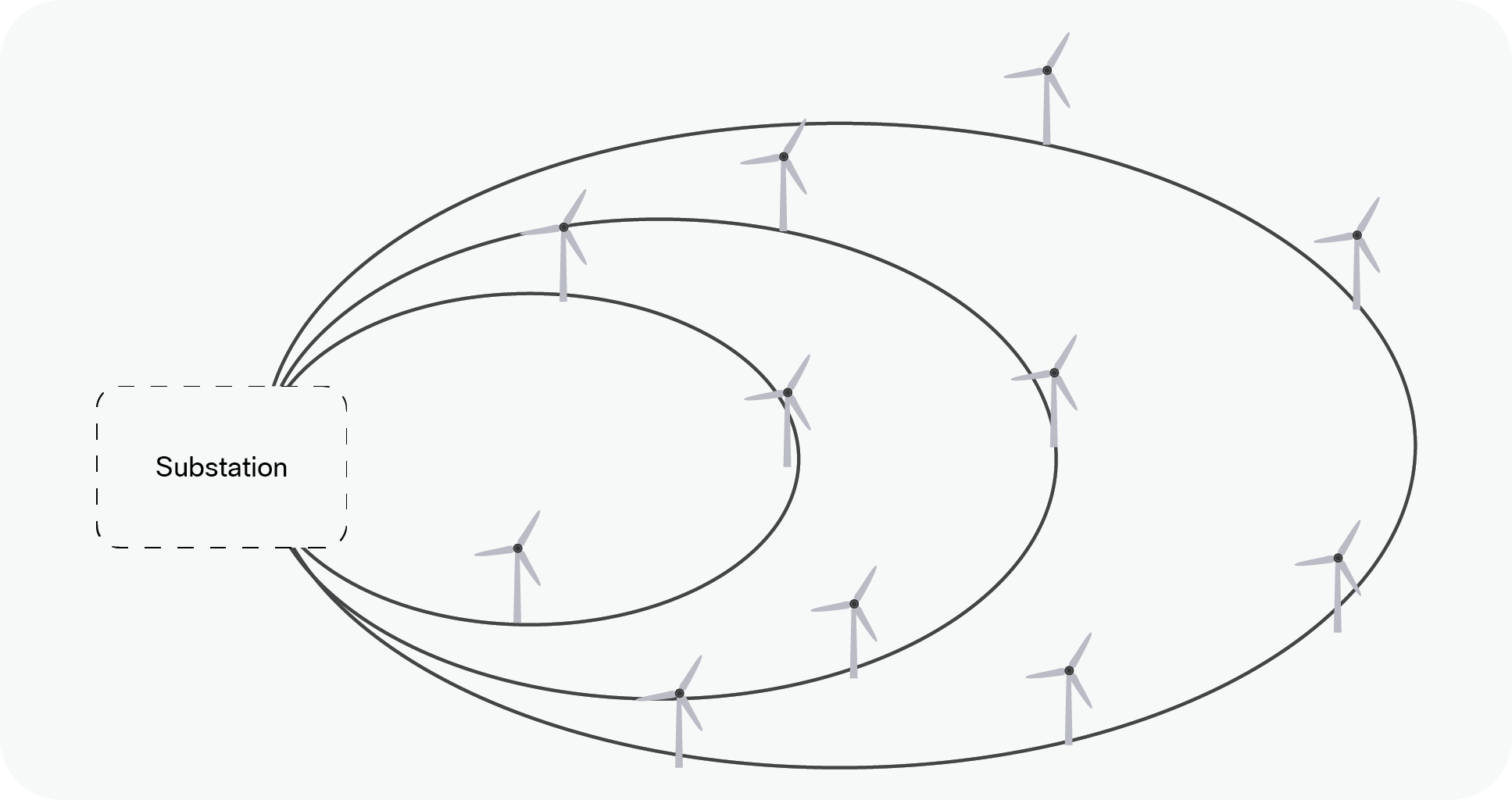
Turbine network topologies vary but generally follow the principle of “strings” or “rings” for a subset of turbines within the farm.
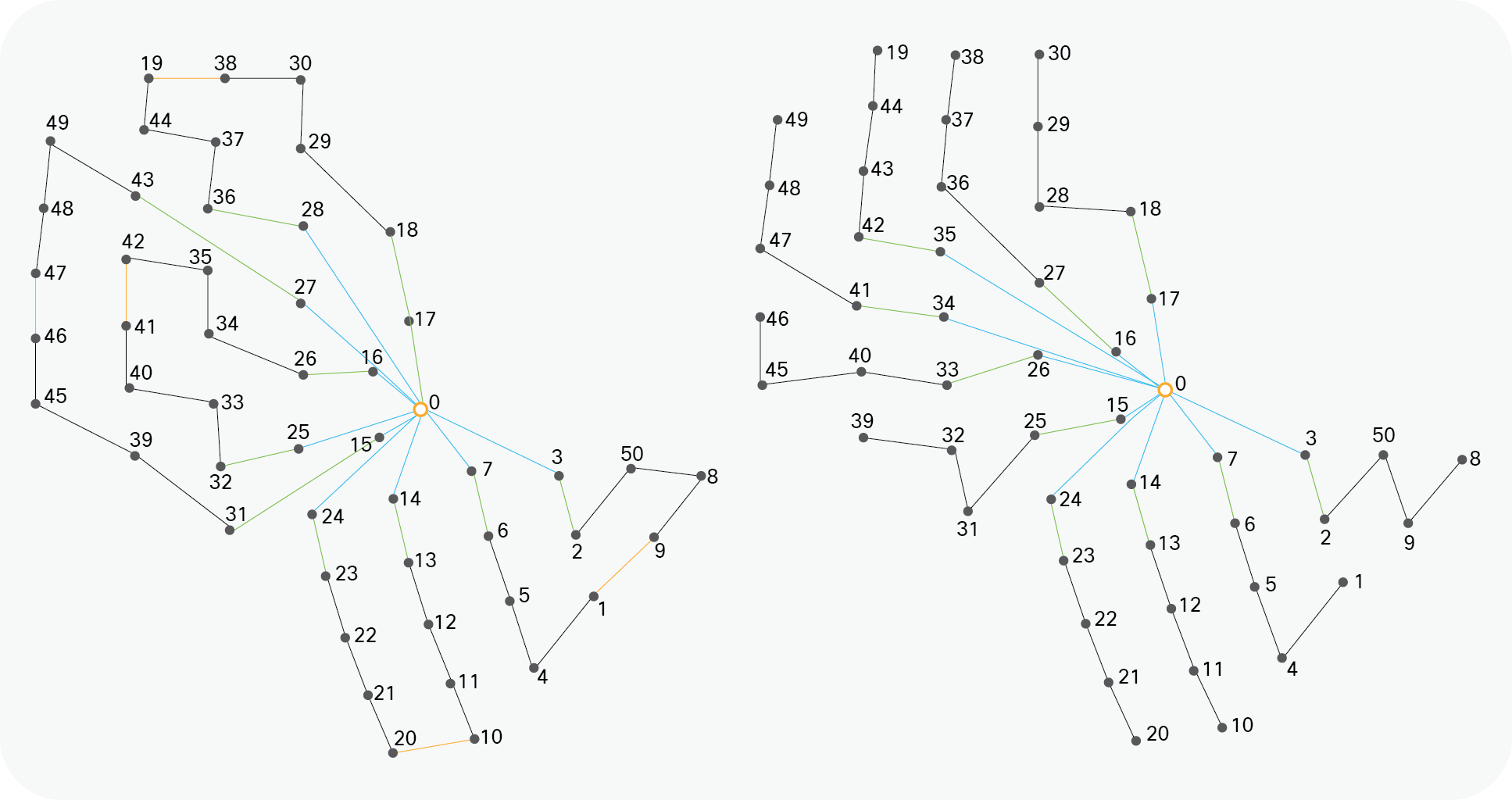
Turbine rings and string topologies
The offshore or onshore substation is connected to multiple turbines via a ring topology as shown below where the offshore/onshore substation forms the aggregation point for all turbine traffic.
At the substation, resiliency is more important as we are now connecting multiple turbine rings and potentially acting as a central aggregation point for the whole network. Thus redundancy features such as switch stacking (physical or virtual) become necessary.
Offshore/Onshore Substation
The substation has a central role in providing connectivity between the elements of the network, for example the turbine SCADA network, power automation, and enterprise backend systems. A failure in the substation can be very critical and result in serious impact to the wind farm operations. Similarly, the fiber connection to the turbines is also critical, because losing this connection can result in loss of connectivity to one or more turbines. Consequently, the substation and connectivity to turbines are designed with a strong focus on high availability.
High availability at the turbine level is of course also important. However because a failure most likely will impact only a single turbine and not the entire wind farm, high availability is less of an issue. This does not mean that relevant measures should not be put in place, but at the turbine there is a different balance between high availability and costs.
The high availability design ensures that the network recovers rapidly after a failure in a network component. The design is based on redundancy on various levels of the network as well as at the different locations of the network.
Wind farms require substantial IPv4 address space, split into various subnets to be applied across the major components within the wind farm. An example is shown below:
● Field wide /21
◦ Onshore plant IT /24 (Total 8 x /24)
◦ Onshore DMZ /24
◦ Offshore DMZ /24
◦ Offshore power automation and control net /24
◦ Offshore admin net /24
◦ Offshore security net /24
● Ancillary systems /20 (Total 16 x /24)
◦ Onshore ancillary net /24
◦ Offshore ancillary net /24
● WTG SCADA network /20 (Total 128 x /27)
◦ Per string SCADA devices (based on 10 turbines per string) /27
◦ Per string network devices (based on 10 turbines per string) /27
◦ Per string IP telephony devices (based on 10 turbines per string) /27
◦ Per string protection devices /28 (based on 1 per turbine)
◦ Per string additional VLANs /27 or /28 based on device count
However, it should be noted that IPv6 could be used, but challenges exist for legacy industrial protocols and devices that do not natively support IPv6 addressing today.
At the substation, the use of node redundancy implicitly provides a topology with redundant links. In other words, the substation contains backup links that are readily available in case of failure. Similarly, the ring network provides link redundancy by connecting in a full circle. This section describes the use of appropriate Layer-2 control protocols to ensure the best path is chosen based on the topology, before or after a fault.
Spanning Tree
In the substation, Layer-2 redundancy and loop prevention are provided on the access and router ports by use of spanning tree protocol (STP). Specifically, the variation multiple spanning tree (MST) is selected as the protocol to ensure high availability in case of node or link failures as well as to ensure protection against loops. Similarly, MST is used in the turbines as a loop prevention mechanism.
MST allows for fast convergence, typically in less than a second, compared to other STP variants, which typically take up to 50 seconds to converge. At the same time MST allows the mapping of multiple VLANs to a single STP instance, which provides scalability to the design and thus support for a high number of turbines.
Use of MST however is less flexible than other STP variants. Thus it is recommended that the switches are configured with all necessary VLANS at deployment time to avoid the need of adding (or removing) VLANs to the MST instance while in operation.
Resilient Ethernet Protocol
A fiber ring connects the substation to each of the turbines, while connecting full circle back to the substation, hence the name “fiber ring.” As a consequence, the ring topology provides link redundancy as it allows the traffic to reach its destination via two directions. If the ring breaks at some point, for instance a fiber breakdown or a failure in the connecting turbine switch, traffic will be redirected to flow the other way around the ring.
To ensure high availability and fast convergence in the fiber rings, the design utilizes the Resilient Ethernet Protocol (REP), which has been specifically designed for ring topologies to achieve fast convergence in 50 ms or less. For the fiber rings connecting the turbines this is very desirable, since the frequency and probability of a link failure in the fiber ring is likely much higher than in the controlled environment of a substation.
Similarly, REP is used within the substation for connections between the switches as this provides both fast convergence and also more flexibility in terms of adding additional switches to the substation.
The following figure shows the combined use of STP and REP in the Layer-2 domain ring protocol comparison and capabilities:
| Protocol |
Topology |
# of Nodes |
Typical Convergence |
Remark |
| RSTP/ MSTP |
Any |
Max hop 255 |
50ms–6s |
Interoperable with third-party switches, not well suited for ring topologies |
| MRP |
Ring |
50 |
200–500ms |
Interoperable with third-party equipment that support the IEC 62439-2 standard. |
| REP |
Ring |
Unlimited |
50–250ms |
(Cisco Proprietary) Convergence depends on the number of nodes in the ring, supports VLAN load-balancing and other configurable options (define edge port location on the ring, multiple gateways for connection to upstream networks, RSTP topology notifications) |
| FAST REP |
Ring |
Unlimited |
<25ms |
(Cisco Proprietary) Supported on IE3x00 only, beacon-based fault detection on links allows a faster REP ring convergence time with all the same standard REP features |
Substation as a DMZ point
The substation design includes the use of a demilitarized zone (DMZ) and firewalling in order to control the traffic, which is allowed to and from the different zones of the network (often run by different parties).
By using a DMZ and establishing different security zones, it is possible to segregate and control traffic flows and thus ensure that only relevant and allowed traffic can enter the various parts of the network.
Power Automation and Control
The onshore and offshore substation power automation network should follow the Cisco Substation Automation design. As shown below, this provides a validated architecture to support operation of the power control element of the wind farm.
The validated design conforms to the IEC61850 substation design using Ethernet and IEC62439 PRP for both the Station and Process Bus (Process Bus is optional and not a mandatory requirement if hardwired sensors are used).
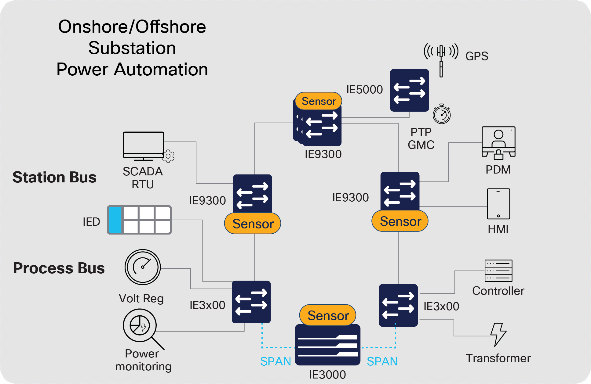
Cisco Substation Automation Design
Switches within the turbines provide the local connectivity for switchgear and IEDs, which connect back to the main onshore/offshore substation via the turbine network rings (separate VLANs used to segregate power automation traffic from turbine SCADA data).
IEEE 1588 PTP synchronization (Stratum 1) within the substation can be provided by a dedicated Cisco IE5000 switch supporting a direct GPS connection and providing the PTP Grandmaster clock with a Power Profile configured on all substation switches.
The key additional requirement is that there is a requirement to extend connectivity to the turbine switchgear/IEDs from the offshore power automation network . Hence rings are required to connect each turbine back to the substation. This network is independent of the SCADA network utilising dedicated fibres. Separate switches are required for each turbine and a zero packet loss ring protocol such as IEC62439 HSR should be used and suitable Redboxes used to interface between the HSR rings and the substation PRP network.
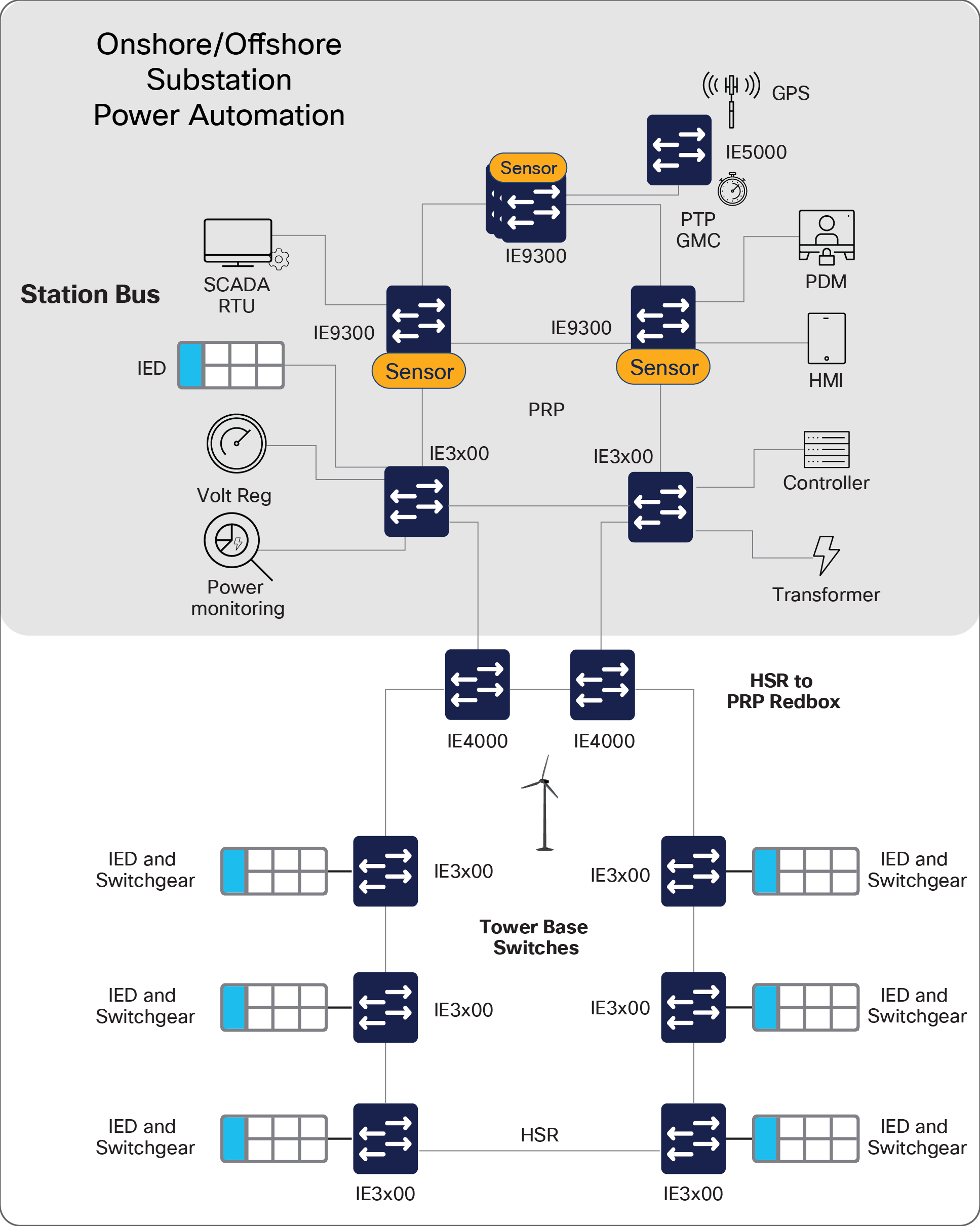
Within the substation resilient network topologies can be used:
| Protocol |
Topology |
# of Nodes |
Typical Convergence |
Remark |
| RSTP/ MSTP |
Any |
Max hop 255 |
50ms–6s |
Interoperable with third-party switches, not well suited for ring topology |
| MRP |
Ring |
50 |
200–500ms |
Interoperable with third-party equipment that support IEC 62439-2 |
| HSR |
Ring |
50 |
0ms |
Interoperable with third-party equipment support on IE-4000, IE-4010 and IE-5000, IEC 62439-3 Clause 5 |
| PRP |
Any |
unlimited |
0ms |
Interoperable with third-party equipment duplicate LANs, IEC 62439-3 Clause 4 |
| REP |
Ring |
unlimited |
50-250ms |
(Cisco Proprietary) Convergence depends on the number of nodes in the ring , supports VLAN load-balancing |
| FAST REP |
Ring |
Unlimited |
<25ms |
(Cisco Proprietary) Supported on IE3x00 only, beacon-based fault detection on links allows a faster REP ring convergence time |
Parallel Redundancy Protocol (PRP) and High-Availability Seamless Redundancy (HSR) are validated in the Cisco substation automation design.
Ancillary Services
A number of ancillary devices and systems are also found on many wind farms. Systems such as weather station sensors, VHF/UHF radio base stations, radar (offshore), lidar, meters, and navigation aids such as tower lights need to be linked to the network for connectivity.
Connection to the enterprise IT network (at the turbines) or dedicated VLANs within the turbine SCADA network are both possible options.
These services can be segregated and connected back to the aggregation switches at the onshore/offshore substation DMZ.
Offshore/Onshore Transmission (Export Cable)
For offshore wind farms, the export cable that provides the power link between the offshore substation and the onshore substation is often owned and operated by another third party.
Fiber pairs provide the connectivity from offshore to onshore, utilizing technologies such as Coarse Wave Division Multiplexing (CWDM) or Dense Wave Division Multiplexing DWDM to maximize the distance possible and also to provide multiplex capabilities on each pair of fibers if needed to maximize the capacity.
The Industrial Ethernet infrastructure is often installed and maintained by personnel with minimal networking background. The result is often network configurations that are consistent when first brought into operational mode but that drift with time, as network infrastructure is rarely if ever maintained or improved. This results in inconsistent configurations, uneven network device software images, and erratic security settings, all of which affect system performance.
With the increase in cybersecurity risks, the increased need to provide end-to-end connectivity while maintaining the highest levels of availability results in a critical need to consistently deploy more sophisticated configurations and maintain them throughout the network’s useful life. Industrial automation systems rely on the consistent, repeatable, and maintainable deployment and operation of sensors, controllers, and other equipment. Why should this not apply to the network infrastructure?
Cisco DNA® Center focuses on deploying and maintaining network infrastructure with automation, bringing consistency, reduced effort, and reliance on simplified workflows for both IT and OT personnel. In many ways, Cisco DNA Center can be viewed as the “controller” for the network infrastructure. Key use cases supported by Cisco DNA Center automation features include:
● Discovering existing network infrastructure, adding to the inventory, and establishing telemetry (e.g., SNMP, syslog, and end-device tracking)
● Providing a network topology view with key status information
● Using network Plug and Play to automatically detect and provision new network infrastructure
● Backing up network configurations and replacing malfunctioning network infrastructure (RMA process)
● Checking for inconsistent configurations and deploying updates scalable and consistently
● Deploying Quality-of-Service (QoS) values based on templates
● Creating application policies for visibility of QoS
● Deploying network software images and patches automatically and at scale
● Performing compliance checks for configurations and software images
● Providing OT with functions relevant to their responsibility
● Deploying applications onto the edge-capable network infrastructure1
● Preparing network infrastructure for Cyber Vision sensor deployment
● Maintaining an audit log for all network changes for accountability
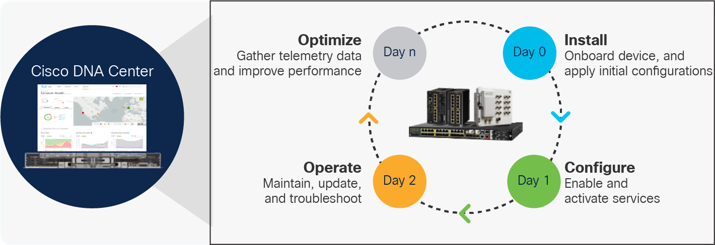
Cisco DNA Center Automation Functions
Key use cases supported by Cisco DNA Center assurance features include:
● Collect and analyze network telemetry information including SNMP, syslog, and IPFIX/Netflow data
● Identify and profile end devices connected to the network and their connectivity status as identified by Cyber Vision and communicated via ISE
● Proactively identify issues in the network that impact operations
● Collect contextual information for accurate root-cause analysis without the need for recreating the issue
● Help step through remediation options to speed issue resolution
● Examine VLAN settings for solving reachability issues
● Provide network and device health monitoring status and history
● Machine Reasoning Engine to accelerate remediation of issues
● Provide security compliance views to indicate potential risks
● Tools such as path trace and packet capture to aid in problem resolution
● Customizable to allow OT and IT specific roles based on feature-set and location/site
Ease of Use
It is a key requirement to enable ease of use of networking devices during the operational phase. This is enabled by features such as:
● Local user GUI on industrial switches and routers for configuration and troubleshooting when Cisco DNA Center is not used or for local engineers
● SD card backup of config and operating system to enable a simple swop out of faulty hardware
● Switch-level features to enable easy replacement of failed devices:
◦ REP auto discovery
◦ SD card replacement (config + firmware backup)
● Dying gasp: syslog and/or SNMP trap sent on power failure
● Alarm contacts: External alarms can be connected to network devices and provide notification of an event (common alarm bus, contact open/closed etc.)
When asset operators attempt to secure their operational network, they encounter three primary issues:
● A lack of visibility: Asset operators often don’t have an accurate inventory of what’s on their industrial network. Without this, they have limited ability to build a secure communications architecture.
● Visibility of communication flows: A lack of visibility also means operators are often unaware of which devices are communicating, and where those communications are going. You cannot control what you cannot see.
● Collaboration: OT devices and processes are managed by the operations team. Cybersecurity is generally driven by the IT and security teams. All these stakeholders need to collaborate to build the specific security policies and enrich events with context so that security does not disrupt production.
Addressing these issues and building a secure industrial network will not happen overnight. To ensure success, Cisco promotes a phased approach where each phase builds the foundation for the next so that you can enhance your security posture at your own pace as you demonstrate value to all stakeholders.
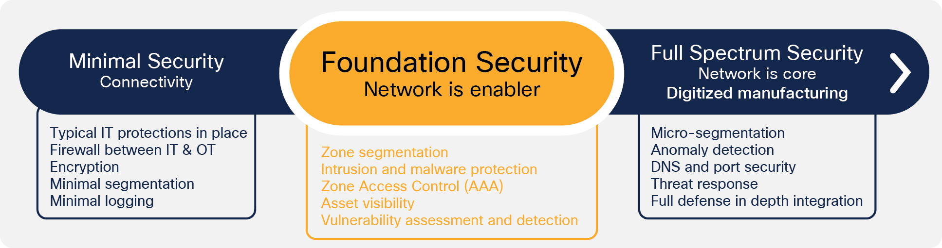
The move from Minimal phase to Foundational is about establishing, controlling, and segmenting zones and traffic flows between those zones. Separation of IT and OT is one example and should be completed as defined in Minimal. The idea to take it to the next level is to segment and monitor traffic across the WAN and provide segmentation in the substations with logging. An IoT “aware” firewall is a perfect fit here.
Identify: Unknown and unpatched assets
Industrial networks have gone virtually unchanged for many years with assets operating in place for decades. Asset discovery often requires time consuming, costly, and even hazardous manual inspections that are error prone and may easily become obsolete. This is a security risk and a compliance issue. Cisco Cyber Vision can discover these devices automatically, providing significant levels of device detail and security posture assessments.
Protect: Lack of separation and segmentation
Separation and segmentation are the basis of security best practices, providing numerous points of inspection. Separating and controlling the flow of malicious traffic are best accomplished at the network level.
Many regulatory bodies such as NERC-CIP, the International Electro technical Commission (IEC), the National Institute of Standards and Technology (NIST), the European Union Agency for Cybersecurity (ENISA) and others are dictating the separation and segmentation of operational and monitoring, control traffic, physical security, and the wider IT traffic from each other throughout the network. The Cisco secure firewalls security appliances, Cisco TrustSec®, and encryption techniques are part of the Cisco Secure Architecture that leverages these tools to achieve the system-wide segmentation required.
Protect: Data privacy and integrity
Asset operators depend on secure data transport for real-time data monitoring, remote operational modifications, and results. Compliance mandates separation of critical data and the encryption of data exiting a physical perimeter. Logging information must also be securely delivered and maintained. Data privacy is a foundational tenant of our secure architecture. Data security leverages port security on Cisco industrial Ethernet switches, and uses a wide variety of encryption technologies on the ISA 3000 or any of the Cisco Industrial Routers IR1101, IR8340, etc.
Detect and respond
Customers face several challenges when it comes to detecting and responding to cybersecurity attacks. The first is a lack of visibility. Operators can stop only malicious activities that they can see. Another is a lack of reliable mitigation. Stopping cyberattacks requires a variety of cybersecurity technologies working together seamlessly, including a fully integrated security architecture that can discover threats and provide the information necessary for mitigation. The solution includes Cyber Vision, Stealthwatch, SecureX, and the ISA 3000 industrial firewall.
Defense in depth
A solid security architecture leverages a defense-in-depth approach. This guide details the integration of multiple security tools and devices to accomplish this in an OT environment, which Cisco refers to as Internet of Things (IoT) Threat Defense. This holistic “full spectrum” security solution addresses the unique requirements of the utility network with best practices and compliance requirements like those found in NERC CIP and IEC 62443 and the NIST framework.
This solution is based on industry-leading innovations in Cisco IoT security and networking technologies that are built into Cisco Cyber Vision, Cisco 3000 Series Industrial Security Appliances (ISA), Cisco IC3000 Industrial Compute Gateway, and Cisco Industrial Ethernet Series Switches with integration with Cisco Identity Services Engine (ISE), Secure Network Analytics (formerly Cisco Stealthwatch), and Cisco TrustSec.
These integrated systems improve operational capabilities and protection to systems; the integration and centralized management significantly reduce operational costs, time, and exposure for the Asset Operator. This is the benefit of a one-source system versus integrating numerous point products from multiple vendors.
Remote access is necessary for the ongoing operations and maintenance. The main types of access are as follows:
● Remote access via VPN from the turbine network to the control/maintenance center for the turbine O&M partner.
◦ This is currently provided via a dedicated router within the turbine network to the external O&M partner control/maintenance center via a secure IPsec tunnel. Recommendations would be for this IPsec tunnel to route via the wind farm operator network and exit via the central data centers (via the internet or dedicated connections to the supplier O&M center) where access can be controlled. However, this method restricts the wind farm operator from inspecting traffic between the O&M center and the turbine network. It does rely on the turbine network O&M partners security capability, and this may not meet the wind farm operator’s requirements for visibility (plus logging and auditing). A more secure solution would be to utilize a proxy server within the wind farm operator DMZ to provide visibility of the traffic traversing to/from the external wind farm O&M partner. The addition of any other local “back door” connections at the wind farm that connect directly to the turbine network is not recommended.
● Remote access for wind farm operator staff and contractors
◦ Remote access has not been specifically addressed in this solution, as the recommendation is for remote workers and third-party contractors to follow the enterprise supported solution. Cisco provides a well-integrated solution with Cisco AnyConnect® and next-generation firewall (NGFW) that can also include multifactor authentication with Cisco Duo. This solution is described in other Cisco designs.
◦ As with many industrial networks, the use of remote access servers or jump hosts is recommended for users requiring access to devices within the lower layers of the industrial network. Jump or bastion hosts should be provided to restrict users to the necessary applications required.
Switching
For the onshore or offshore substation switching component, the switch choice is based on the use in the architecture. Both Enterprise Catalyst and Industrial Ethernet switches are used.
| Component |
Description |
Comments |
| Catalyst 9300/9500 |
Non-power automation, Enterprise IT, and DMZ networks |
Switch for aggregation and interconnection of the various networks. Capability to be physically or virtually stacked for resiliency. |
| IE9300 |
Substation automation network |
Rackmount substation certified switch |
| IE3x00 |
Substation automation network |
DIN rail-mounted substation certified switch; for Cisco TrustSec support the IE3400 is required and the IE3300 performs as a Layer 3 switch. |
Routing
The onshore substation routing component connecting to the wind farm operator WAN should support a variety of WAN interfaces. Thus it is able to connect using almost any type of connection, including cellular (3/4/5G) and DSL, and also IPsec (FlexVPN, Dynamic Multipoint VPN [DMVPN] etc.) capabilities plus SD-WAN support as an option.
Depending on the size of the wind farm, the router choice can vary. In the following table, some of the relevant models are listed. Please note that besides the difference in performance, the models also vary slightly, e.g. in terms of available slots for modules and/or WAN interface cards.
| Component |
Description |
Comments |
| IR8340 |
Cisco industrial rack-mounted WAN router and switch |
Substation certified industrial router with built-in switch capability. Supporting integrated Cybervision Sensor, Edge Compute capability, iming module, 2 x cellular WAN modules, and supporting SD-WAN or MPLS WAN capability |
| ISR4400 |
Cisco enterprise rack-mounted router |
The Cisco 4000 Series Integrated Services Routers provide routing, hosting, security, switching, and application visibility—all in a single, trustworthy platform. Quickly adopt advanced technologies—such as SD-WAN, enhanced application visibility, and Edge computing |
| IR1101 |
Cisco industrial DIN rail-mounted compact WAN router for smaller wind farm sites |
Substation certified industrial router with built in 4-port switch capability. Supporting integrated Cybervision Sensor, Edge Compute capability, 2 x cellular WAN modules and supporting SD-WAN capability. |
The exact model mainly depends on the required performance. This again mainly depends on the WAN bandwidth as well as which software features are required.
Security
Besides the switching and routing components of the substation, a security appliance is also required to provide the firewall functionality. For this purpose, a Cisco Firepower® appliance is recommended.
| Component |
Description |
Comments |
| Cisco Secure Firewall 2100 or 4100 series |
Firewall appliance |
Providing access control between the various networks and the offshore/onshore DMZ Also providing intrusion capabilities into supported protocols (including industrial protocols) |
| ISA3000 |
Industrial DIN rail-mounted firewall |
Provides firewall function for substation certified requirements or areas where DIN rail mounting is required. Also providing intrusion capabilities into supported protocols (including industrial protocols) |
| Firepower Management Center (FMC) |
Firewall management and configuration |
FMC supports both Cisco Firepower and ISA3000 platform configuration and monitoring |
| Identity Services Engine (ISE) |
Security policy and network access platform |
The Cisco Identity Services Engine (ISE) is a one-stop solution to streamline security policy management and reduce operating costs. With ISE, you can see users and devices controlling access across wired, wireless, and VPN connections to the corporate and plant networks. |
Management
| Component |
Description |
Comments |
| Cisco DNA Center |
Management appliance |
Cisco DNA Center is a powerful network controller and management dashboard that lets you take charge of your network, optimize your Cisco investment, secure your remote workforce, and lower your IT spending. Full automation capabilities for provisioning and change management are enhanced with AI/ML-enhanced analytics that pull streaming telemetry from everywhere in the network. |
| SD-WAN |
SD-WAN solution |
Cisco SD-WAN offers a software-defined WAN solution that enables enterprises and organizations to connect users to their applications securely. It provides a software overlay that runs over standard network transport, including MPLS, broadband, and internet, to deliver applications and services. The overlay network extends the organization’s network to Infrastructure as a Service (IaaS) and multi-cloud environments, thereby accelerating the shift to the cloud. |
| Cisco DNA Spaces |
Location-based Services |
Cisco DNA Spaces use location analytics to gain more insights into the behavior of people and things and how they interact in your physical spaces. |
In the turbine, the recommended switching component is the Cisco Industrial Ethernet IE3x00 series, which have specifically been designed for harsh environments, such as found in turbines. The switch comes in different models depending on port requirements, among others. The following table shows the recommended switch models per turbine according to requirements.
| Component |
Description |
Comments |
| IE3300 |
Cisco Industrial DIN-Mounted Ethernet Switch with POE |
Nacelle switch (turbine SCADA), single downlink to tower switch. Required quantity is 1 per turbine. |
| IE3400 |
Cisco Industrial Rackmount-Mounted Ethernet Switch with POE and supporting edge compute and with support for Trustsec |
Nacelle switch (Enterprise), single downlink to Tower switch. Required quantity is 1 per turbine. Supports embedded Cybervision sensor. |
| IE3300 |
Cisco Industrial DIN-Mounted Ethernet Switch with POE |
Tower switch (turbine SCADA), 2 fiber uplink ports. Required quantity is 1 per turbine. |
| IE3400 |
Cisco Industrial Rackmount Ethernet Switch with POE and supporting edge compute and with support for Trustsec |
Tower switch (Enterprise), 2 fiber uplink ports. Required quantity is 1 per turbine. Supports embedded Cybervision sensor. |
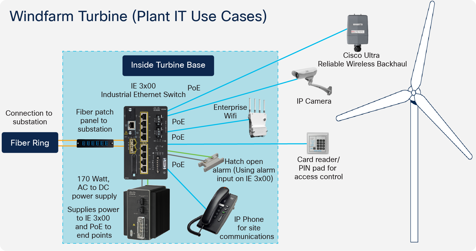
It is possible to also equip each turbine with Wi-Fi for worker mobility (enterprise services, SCADA access via tablet, portable IP telephony handsets) and safety use cases. Bluetooth is used for local worker safety devices (for example, Man Down).
Cisco Ultra Reliable Wireless Backhaul (URWB) can provide a wind farm–wide canopy of high-bandwidth connectivity outside the turbines. This hardware is used to connect smaller crew transfer vessels as they roam within the wind farm or connecting assets not directly connected to the fiber rings (e.g., navigation masts).
| Component |
Description |
Comments |
| Catalyst 9000 series AP |
Wi-Fi and Bluetooth access point |
Wi-Fi use cases and Bluetooth for worker mobility and safety use cases. For use internally within the turbines. Outdoor model also available. Supported by Cisco DNA Center. |
| FM3500 |
Cisco URWB Radio |
Point-to-multipoint connectivity for mobile use cases |
| FM1000/10000 |
Cisco URWB Gateway |
Centralized URWB gateway |
| IW6300 |
Ruggedized Wi-Fi access point |
Wi-Fi access point with industrial certifications and IP67 rating |
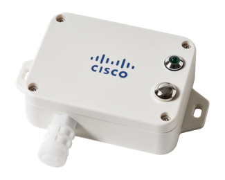
Environmental Sensors
A number of use cases can be leveraged using the Industrial Asset Vision solution. The solution can be deployed with an external gateway with no requirement to connect directly to the turbine SCADA network.
A wind farm operator can deploy Industrial Asset Vision gateways to cover a large area and provide a long range low power wireless network for the various sensors supported by the solution. The gateway requires either a cellular backhaul router or can be connected to any available network switch port. The gateway is POE+ powered.
Industrial Asset Vision is a hosted service on the Cisco cloud. The gateway therefore requires network access to reach the public internet. All data is secured from the gateway via IPsec plus the sensor data payload is further encrypted by the sensor.
| Use Case |
Sensor |
Measurements |
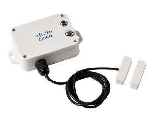
| Tower door entry |
AV204 |
Door Open or Close event 60-min reporting interval Expected battery life 5 years (with <100 triggers per day) |
| Nacelle temperature and humidity |
AV201 |
Internal temperature and humidity within the nacelle or tower 15-min reporting interval Expected battery life 5 years |
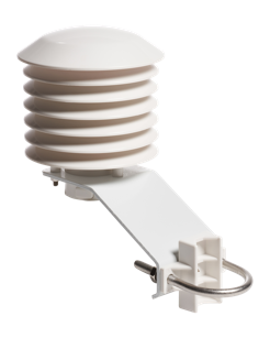
| External temperature and humidity |
AV200 |
External temperature and humidity 60-min reporting interval Expected battery life 4 years |
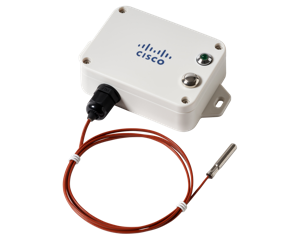
| Machine temperature |
AV250 |
Used to detect temperature of an environment or to a medium to which its thermocouple is connected 15 min reporting interval Expected battery life 4.5 years |
Industrial Asset Vision provides a cloud-based portal for management of the gateways and sensors. Data from the sensors is viewed on pre-built dashboards or can be extracted via a Message Queue Telemetry Transport (MQTT) interface to an external platform. Below is an example view of a Turbine Nacelle Asset with three sensors deployed monitoring internal temperature and humidity at various points.
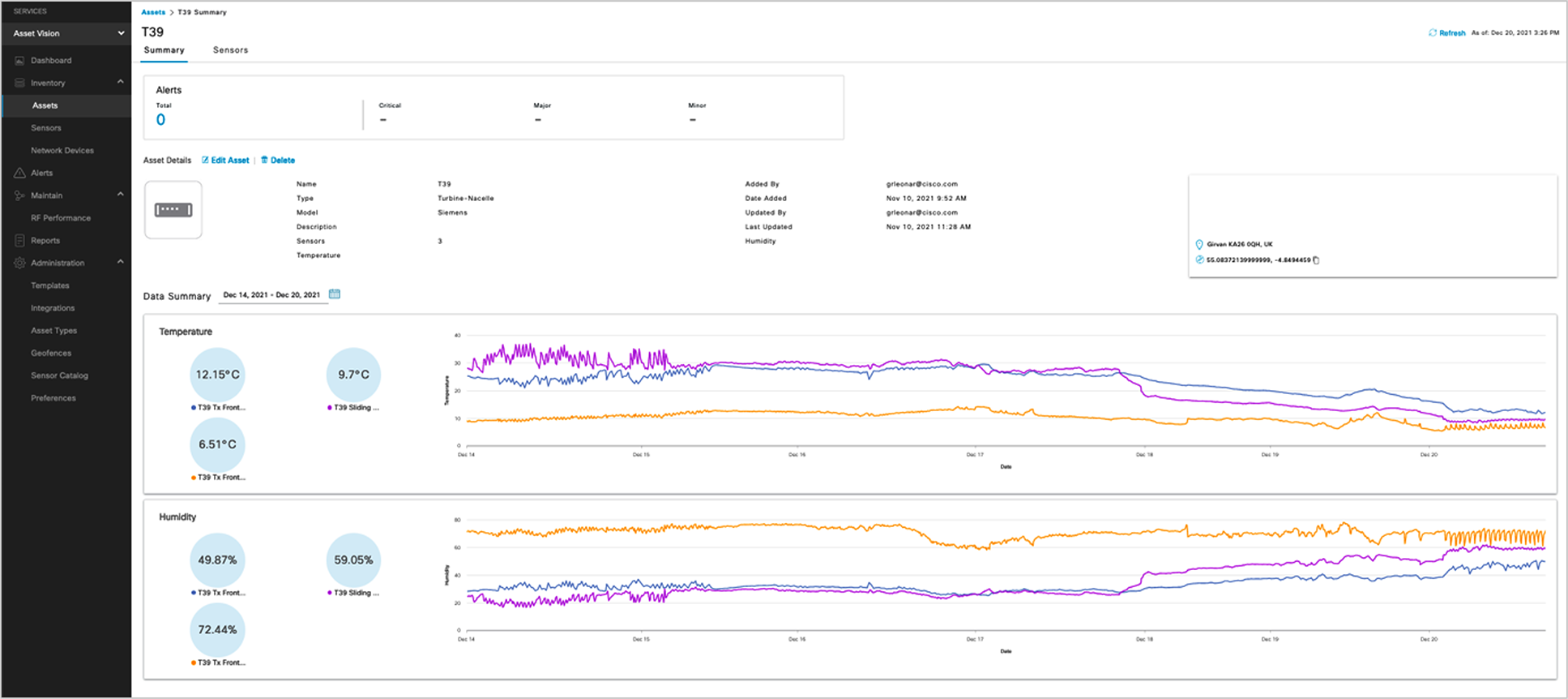
Industrial Asset Vision Dashboard
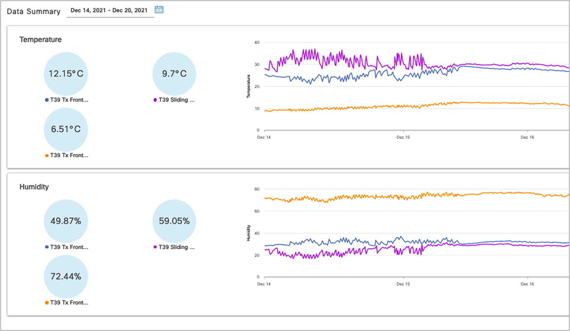
Temperature and Humidity with a Turbine Nacelle
Service Operations Vessel (SOV) Connectivity Offshore
There is a need for a reliable, high-bandwidth wireless backhaul solution that connects to the large Service Operations Vessel (SOV) as well as smaller Crew Transfer Vessels (CTVs) that move staff around the offshore wind farm estate.
During periods near shore, the vessel should utilize public cellular connectivity.

Service Operation Vessel (SOV)
Requirements are as follows:
● Reliable wireless backhaul connectivity to the vessels that are within a 10 km radius around the offshore substation platform (OSS) using Cisco Ultra Reliable Wireless Backhaul radios.
● The head end or wayside will be on the OSS.
● Vessels shall have specialist antennas with appropriate radios and modems.
● Antennas shall automatically adjust their direction to optimize the radio signals for best performance (by using a GPS feed to dynamically change the beam direction).
● The antennas should be a combination antenna capable of 5 GHz Cisco URWB wireless and public LTE.
● Target throughput: 30 to 50 Mbps for the SOV at the 10 km distance from OSS.
● The solution should also use LTE—when the SOV is going to/from harbor (this should extend to a few miles offshore).
● IP telephony to be extended to the SOV with Survivable Remote Site Telephony (SRST) preferred onboard for periods where no connectivity is available.
● Corporate and guest user networks to be extended to the SOV (fixed and Wi-Fi).
The following table shows a list of selected North American Electric Reliability Corporation /Critical Infrastructure Protection (NERC/CIP) requirements with reference to how/where the network design can support the customer in becoming NERC/CIP compliant.
As achieving NERC/CIP compliance is not only about technology support but also about establishing and maintaining business processes, the table should not be viewed as a definitive solution to becoming NERC/CIP compliant, rather as an indication of how the design and its technologies may support customers in becoming NERC/CIP compliant.
| Number |
Title |
Requirement |
Technology support |
| CIP-003-03 |
Cybersecurity, Security Management Controls |
R5, Access Control |
Use of TACACS+ as part of the Cisco Secure Access Control Server |
| CIP-005-03 |
Cybersecurity, Electronic Security Perimeter(s) |
R1, Electronic Security Perimeter |
Use of firewall and DMZ to define security perimeter and segregate traffic between security zones |
| CIP-005-03 |
Cybersecurity, Electronic Security Perimeter(s) |
R2, Electronic Access Controls |
Use of technologies such as SSH, HTTPS, IPsec VPN, and IEEE 802.1x |
| CIP-005-03 |
Cybersecurity, Electronic Security Perimeter(s) |
R3, Monitoring Electronic Access |
Use of technologies such as SNMP, syslog and TACACS+ accounting |
| CIP-005-03 |
Cybersecurity, Electronic Security Perimeter(s) |
R5, Documentation Review and Maintenance |
Use of technologies such as SNMP, syslog |
| CIP-006-03 |
Cybersecurity, Physical Security of Critical Cyber Assets |
R4, Physical Access Controls |
Use of secure cabinets and port locks |
| CIP-006-03 |
Cybersecurity, Physical Security of Critical Cyber Assets |
R5, Monitoring Physical Access |
Use of technologies like IEEE 802.1x to detect unauthorized access of ports as well as SNMP and syslog to monitor these attempts |
| CIP-007-03 |
Cybersecurity, Systems Security Management |
R2, Ports and Services |
Use of technologies IEEE 802.1x to protect ports from unauthorized access as well a device hardening by closing unused ports |
| CIP-007-03 |
Cybersecurity, Systems Security Management |
R5, Account Management |
Use of TACACS+ as part of the Cisco Secure Access Control Server |
| CIP-007-03 |
Cybersecurity, Systems Security Management |
R6, Security Status Monitoring |
Use of technologies such as SNMP, syslog and TACACS+ accounting |
The Cisco Grid Security solution design incorporates steps as listed above using various components, NERC-CIP compliance requirements on a centralized architecture. For NERC-CIP compliance requirements and various product mappings, refer to the following table maps various requirements of NERC-CIP and Cisco Grid Security Solution.
NERC-CIP Compliance and Solution Mapping:
| Requirements |
||
| Cisco Cyber Vision Secure Network Analytics (formerly Cisco Stealthwatch |
||
| CIP-005-5 |
ISA-3000 IR-800 and IR1101 CGR-2010 IE-4000 Switches IE-5000 Switches |
|
| Cybersecurity – Configuration Change Management and Vulnerability Assessments |
||