Cisco Catalyst 9400 Series Architecture White Paper
Available Languages
Bias-Free Language
The documentation set for this product strives to use bias-free language. For the purposes of this documentation set, bias-free is defined as language that does not imply discrimination based on age, disability, gender, racial identity, ethnic identity, sexual orientation, socioeconomic status, and intersectionality. Exceptions may be present in the documentation due to language that is hardcoded in the user interfaces of the product software, language used based on RFP documentation, or language that is used by a referenced third-party product. Learn more about how Cisco is using Inclusive Language.
Enterprise campus networks are undergoing profound changes to support ever-increasing bandwidth demands on the access layer while moving toward supporting Wi-Fi 6 (802.11ax) and the rapid growth of powerful endpoints. With access layer bandwidth moving from 1 Gbps to 2.5 and 5 Gbps speeds, higher bandwidth such as 25 and 100 Gbps will become the de facto speeds to maintain a similar over-subscription ratio.
Cisco® Catalyst® 9400 Series switches are the foundation of Cisco’s next-generation enterprise-class access and distribution layer solutions. These are high-end modular switches that come in 4, 7, and 10 slot chassis variations. They deliver exceptional table scales (MAC, route, and Access Control Lists [ACL]) and buffering capabilities for enterprise applications. The switching capacity can go up to 9.6 Terabits per second (Tbps) and up to 3 Billion packets per second (Bpps) of forwarding performance for all chassis. The platform offers nonblocking 40/100 Gigabit Ethernet (GE) Quad Small Form- Factor Pluggable (QSFP), 25 GE Small Form-Factor Pluggable 28 (SFP28), 10 GE Enhanced Small Form-Factor Pluggable (SFP+) and up to 10 Gbps Multigigabit copper ports with granular port densities per module that meet diverse campus needs.
This white paper provides an architectural overview of the Cisco Catalyst 9400 Series chassis, including system design, power, cooling, and storage options.
The Cisco Catalyst 9400 platform is a modular switch built based on the Cisco Unified Access™ Data Plane (UADP) 3.0sec and 2.0 XL architecture, which not only protects your investment but also allows a larger scale and higher throughput (Figure 1). The platform runs on the modern modular, open Cisco IOS® XE operating system, which supports model-driven programmability, has the capacity to host containers with support for up to 1 TB of SSD storage, and can run third-party applications like Docker™ apps and scripts natively within the switch (by virtue of the x86 CPU architecture, local storage, and a higher memory footprint). The modern operating system offers enhanced high availability features like In-Service Software Upgrade (ISSU), Software Maintenance Upgrades (SMU) and StackWise® Virtual Technology. Improved high availability is added also via platinum-efficient, dual redundant power supplies as well as variable-speed highly efficient redundant fans. In addition, Cisco Catalyst 9400 Series platforms are:
● EANTC certified
● NEBS 2 compliant design which makes them appropriate for variety of enterprise environments like cruise ship, aircrafts or colo locations which has strict NEBS requirements
● Provide up to 90W Power Over Ethernet (PoE) based on IEEE 802.1bt standard on up to 260 ports simultaneously
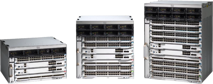
Cisco Catalyst 9400 Series
Chassis come in three types, with 4, 7 or 10 slots. Every chassis offers two slots that are dedicated for supervisors only and work in redundant mode. The backplane on every chassis is passive which brings the following benefits:
● Lower power consumption
● Higher MTBF
● Fan-Tray, Power supplies and Line cards are Field Replaceable Unit (FRU) and they can be replaced non-disruptively
Supervisors come in five types:
● Cisco Catalyst Supervisor Engine-2XL (Sup-2XL) (Figure 2)
● Cisco Catalyst Supervisor Engine-2 (Sup-2)
● Cisco Catalyst Supervisor Engine-1XL (Sup-1XL)
● Cisco Catalyst Supervisor Engine-1XL-Y (Sup-1XL-Y) (Figure 3)
● Cisco Catalyst Supervisor Engine-1 (Sup-1)
Sup-2/2XL supervisor ports are distributed with four 1/10/25 Gbps and three 40/100 Gbps or four 40/100 Gbps. A different combination of uplink ports is also supported.
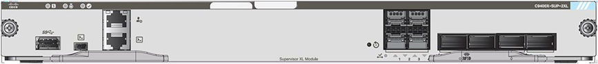
Sup-2XL module with 4x1/10/25-Gbps and 4x40/100-Gbps uplinks
Sup-1/1XL/1XL-Y supervisor ports are distributed with eight 1/10 Gbps or two 25 Gbps (Sup-1XL-Y only) and two 40 Gbps. A different combination of uplink ports is also supported. Sup-1XL-Y does not support MACsec on supervisor ports.
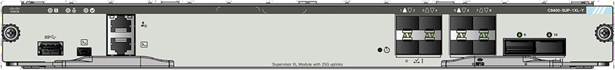
Sup-1XL module with 25-Gbps uplinks
Copper line cards offer the port density shown in Figure 4.
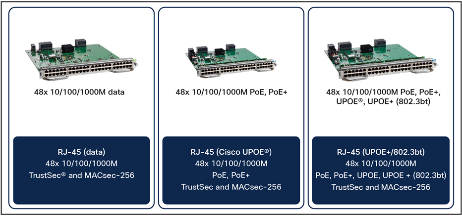
Copper line cards
MultiGigabit line cards offer the port density shown in Figure 5.
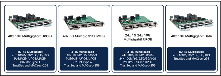
MultiGigabit line cards
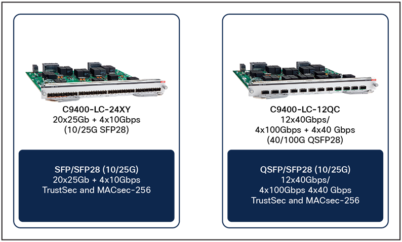
Fiber line cards offer port density shown in Figure 6.
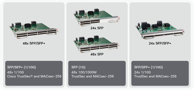
Fiber line cards
This section briefly describes the highlights of the Cisco Catalyst 9400 Series chassis:
The power supplies are “Platinum efficient” or 90% or more efficient.
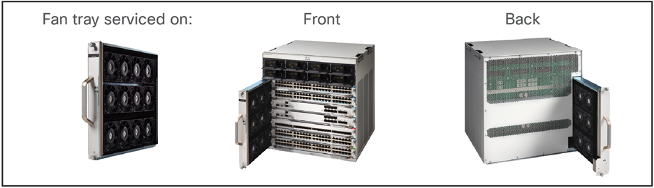
Fan tray with N+1 redundancy and flexible options to serve the fan from the front or back (Figure 7).
Flexible fan-tray servicing
Multirate ports: Every SFP+ port can support dual speeds of 1 and 10 Gbps. Every Multigigabit port supports different speeds of 100 Mbps and 1, 2.5 and 5 Gbps, with speeds up to 5 Gbps on Category 5e (Cat5e) cable and up to 10 Gbps on Category 6/6a (Cat6/6a) cable.
Internal SSD storage of up to 960 GB is installed on the supervisor engine.
An ACT2 chip for module authenticity is supported on all supervisors, line cards, and fan trays.
Table 1 provides information about the capabilities of each chassis.
Table 1. Chassis specifications
|
|
4 slots |
7 slots |
10 slots |
|
| Supervisor |
2 (redundant) |
|||
| Line cards |
2 |
5 |
8 |
|
| Ports |
96x 10/100/1000 96x Multigigabit; 96x SFP/SFP+; Sup2/2XL: 4 SFP28; 4x QSFP28 |
240x 10/100/1000 240x Multigigabit; 240x SFP/SFP+; Sup2/2XL: 4 SFP28; 4x QSFP28 |
384x 10/100/1000 384x Multigigabit; 384 SFP/SFP+; Sup2/2XL: 4 SFP28; 4x QSFP28 |
|
| Dimensions WxDxH |
17.5 in. x 16.25 in. x 6RU |
17.5 in. x 16.25 in. x 10RU |
17.5 in. x 16.25 in, x 13RU |
|
| Bandwidth per LC slot |
480G |
480G |
480G |
|
| Bandwidth between supervisor slots |
720G Sup1/1XL/1XL-Y 800G for Sup2/2XL |
|||
| Power supplies |
4 (N+1 and N+N) |
8 (N+1 and N+N) |
8 (N+1 and N+N) |
|
| Power over Ethernet (PoE) per slot |
4800W |
|||
| Cooling |
Side to side for chassis, front to back for power supplies |
|||
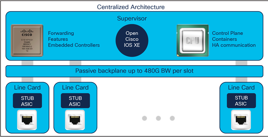
This section briefly covers the high-level system design of the Cisco Catalyst 9400 Series. A centralized architecture is used for all three types of chassis (Figure 8). The architecture offers option to combine two physical chassis as one single logical device using the Stackwise Virtual technology.
Cisco Catalyst 9400 Series architecture
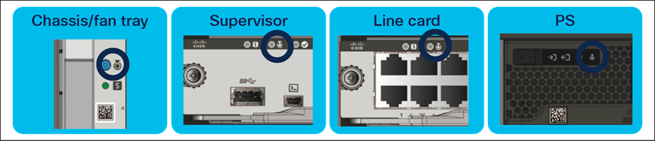
All chassis come with a built-in passive RFID for inventory management and Blue Beacon on every component, which can be managed by the software to turn it on and off, as well as an LED for chassis-level identification and a tricolor LED for system status.
Blue beacon location on different chassis modules
Supervisor also includes a front panel RJ-45 console port, a USB type B connector for the USB console to the CPU, an RJ-45 management port, and a USB 2.0/3.0 host port for storage.
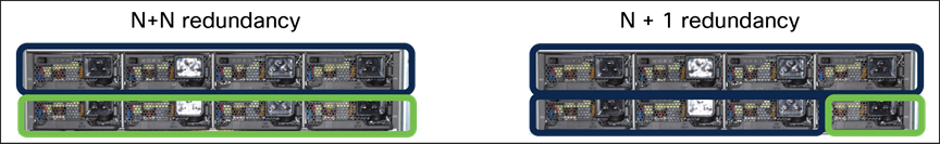
The Cisco Catalyst 9400 Series chassis has N + N or N + 1 power redundancy modes (Figure 10).
Power redundancy modes
To deliver N + N redundancy, an even number of power supplies is required: two, four, six, or eight. If N + 1 is the desired mode, one of the power supplies should be configured for standby operation.
Power supplies are also supported in combinations of AC and DC units.
Every line card slot can provide Cisco UPOE+™ and Cisco UPOE® power, and the priority between the ports and the line cards is configurable to define deterministic behavior in case a power supply is lost.
The maximum output power per power supply for the Cisco Catalyst 9400 Series is listed below, and each Power Supply Unit (PSU) has a power holdup time of approximately 8 milliseconds at 100 percent load. Each PSU comes with front-to-back variable-speed cooling fans and has a push-release lock for simple and secure Online Insertion and Removal (OIR).
● 3200W AC PS with 240V input (1570W with 120V input; 16A input)
● 2100W AC PS with 240V input (940W with 120V input; 10.4A input)
● 3200W DC PS with dual 48V input (44A input)
AC PSUs
Each PSU supports four LEDs to determine the status of the power supply (Table 2).
Table 2. PSU LEDs
| LED |
Color options (ON/OFF) |
Description |
|
| Input power |
|
|
Input voltage(s) is OK |
| Output power |
|
|
Output power is OK |
| Output failed |
|
|
Output power is not in range |
| Beacon |
|
|
Used to indicate the location of the PSU |
The Cisco Catalyst 9400 Series Switches support a hot-swappable and field-replaceable fan tray that can be replaced from the front or back, which offers significant flexibility with different cable management options (Figure 12). The chassis supports side-to-side airflow. The fan-tray unit support OIR for up to 90 seconds. The fan unit is responsible for cooling the entire chassis and for interfacing with environmental monitors to trigger alarms when conditions exceed thresholds. The fan modules contain thermal sensors to detect ambient temperature and adjust the fan speed. The chassis supports a hardware failure of up to one individual fan, where the remaining fans will automatically increase their rpm to compensate and maintain sufficient cooling. If the switch fails to meet the minimum number of required fans, it shuts down automatically to prevent the system from overheating. The number of fans per fan tray depends on the number of slots in the chassis.
Cisco Catalyst 9400 Series chassis are equipped with onboard thermal sensors to monitor the ambient temperature at various points and report thermal events to the system to adjust the fan speeds.

Fan tray for the C9407R model
Insertion and removal of the fan modules are made easy with a fan assembly handle that has an integrated passive RFID (Table 3).
Table 3. Fan and fan-tray LEDs
| LED |
Color |
Status |
Description |
| Fan |
|
Solid |
Fan/Fans OK |
| Fan |
|
Solid |
Tachometer fault |
| Fan |
|
Solid |
One or more fans faulty (tachometer) Exceeded maximum limit |
The Cisco Catalyst 9400 Series fan tray supports side-to-side airflow for the modules and front-to-back airflow for the power supplies (Figure 13).
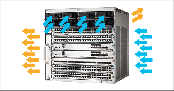
Fan-tray airflow
The Supervisors 2XL offer line-rate for 1/10 Gbps linecards. Sup2 and Sup1/1XL/1XL-Y offer oversubscribed or performance mode for 10 Gbps modules. The oversubscription depends on the chassis type and the chosen supervisor. With latest Sup-2XL all ports on the linecards are non oversubscribed. The supervisors 1/1XL/1XL-Y offer configurable system resources to optimize support for specific features, depending on how the switch is used in the network. The switch architecture consists of four main components.
● UADP ASIC
● X86 CPU complex
● ASIC interconnect
● Front panel interfaces
Figure 14 shows the number of Switch Link Interfaces (SLI) connected from the Supervisor card to the backplane of the chassis. The chassis and the linecards are pre-provisioned with the required number of SLIs to provide full line rate on all the line card ports. If a supervisor module provides lesser number of SLIs than are required for line rate, it causes oversubscription. In this case, replacement of just the supervisor (to a newer generation one) will reduce or eliminate the oversubscription. There is no requirement of replacing the port linecard(s) or the chassis. Information on how many SLIs are connected per Supervisor module and per Chassis is available in the Linecard section of the whitepaper.
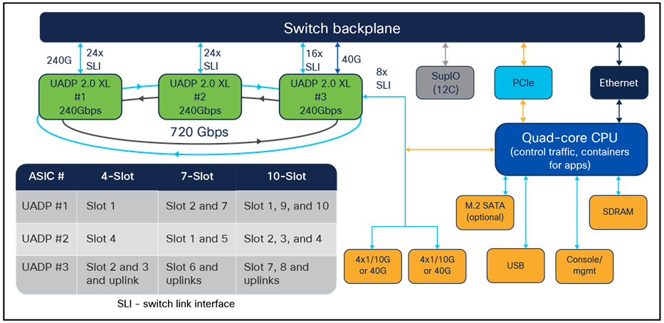
Sup-1, Sup-1XL, and Sup-1XL-Y diagram
Figure 15 shows very similar centralized architecture used for Sup-2XL/2. There are improvements on the ASIC interconnect where the stack ring is replaced by Direct Point to Point (DPP) Connections on higher speed. The SLIs serving the linecards can operate on 30 or 10 Gbps speed.
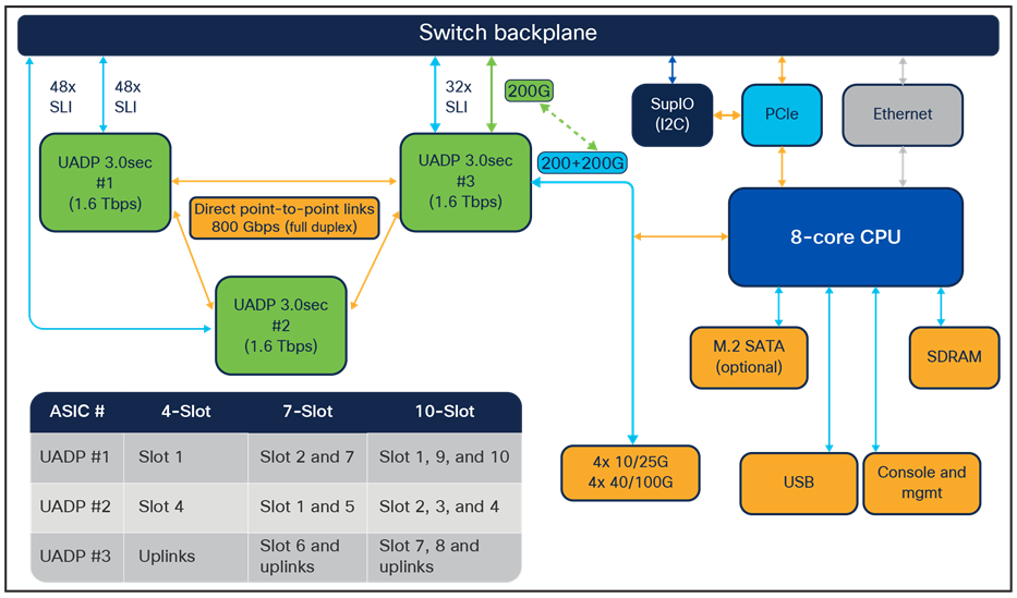
Sup-2XL, Sup-2 diagram
The supervisors 2XL/2 are built on the UADP 3.0sec ASIC, which is based on a System-On-Chip Architecture (SOC).
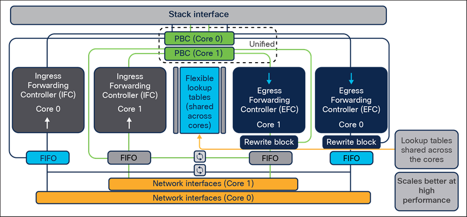
UADP 3.0sec ASIC diagram
UADP 3.0sec is a fourth-generation 1.6 Tbps 2-core ASIC optimized for next-generation Cisco Catalyst modular switches. The architecture and functionality of UADP 3.0sec adds richer programmable capabilities from previous generations and also offers extended table sizes in comparison with 2.0 XL. The UADP 3.0sec ASIC is built using 16-nanometer technology with a 2-core architecture (Figure 16). The UADP 3.0sec ASIC continues to offer programmable pipelines, but also adds flexible table which can be relocated between features.
The list below captures the key UADP 3.0sec capabilities.
● Packet bandwidth/switching throughput: 1.6 Tbps (800 Gbps per core)
● Forwarding performance: 1 Bpps
● DPP bandwidth: 1.6 Tbps
● Forwarding Information Base (FIB) table: Up to 256,000(capable) IPv4/v6 (114,000 default)
● Shared packet buffer: 36 MB (18 MB per core or 36 MB shared between the cores)
● Up to 128K (hardware capable) Netflow entries per ASIC. (Currently 96K Netflow entries per ASIC)
● 54,000 Ternary Content Addressable Memory (TCAM) entries
● Support IEEE 1588 PTP protocol (capable)*
The supervisors 1/1XL/1XL-Y are built on the UADP 2.0 XL ASIC, which is based on a System-On-Chip Architecture (SOC).
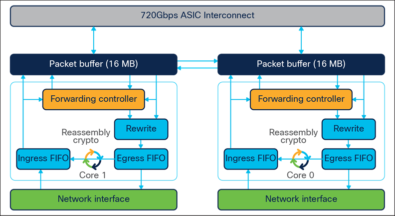
UADP 2.0 XL ASIC diagram
UADP 2.0 XL is a third-generation 240 GE 2-core ASIC optimized for next-generation Cisco Catalyst modular switches. The architecture and functionality of UADP 2.0 XL adds richer programmable capabilities from previous generations and also offers extended table sizes in comparison with 2.0. The UADP 2.0 XL ASIC is built using 28-nanometer technology with a 2-core architecture (Figure 17). The UADP 2.0 XL ASIC continues to offer programmable pipelines, but also adds flexible table which can be relocated between features.
The list below captures the key UADP 2.0 XL capabilities.
● Packet bandwidth/switching throughput: 240 Gbps (120 Gbps per core)
● Forwarding performance: 375 Mpps
● Stack bandwidth: 720 Gbps (2x 360-Gbps rings)
● Forwarding Information Base (FIB) table: Up to 144,000*/56,000* IPv4/v6
● Shared packet buffer: 32 MB (16 MB per core)
● Dedicated NetFlow block with 128,000/64,000 IPv4/v6 (64,000/32,000 per core)
● 54,000 Ternary Content Addressable Memory (TCAM) entries
● Support IEEE 1588 PTP protocol
Figure 18 shows a comparison between UADP 3.0sec and 2.0 XL.
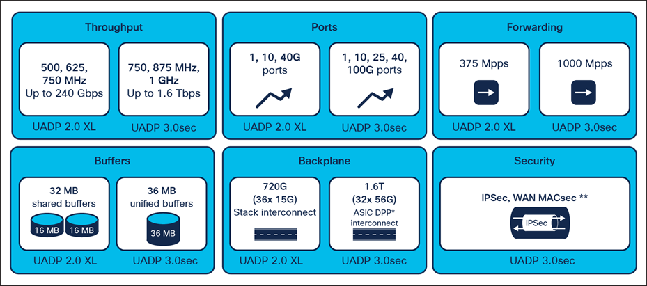
UADP 2.0 XL vs. 3.0sec per-ASIC capabilities
The Cisco Catalyst 9400 Series supervisors 1/1XL/1XL-Y are equipped with the same CPU, system memory, and flash storage (Figure 19).
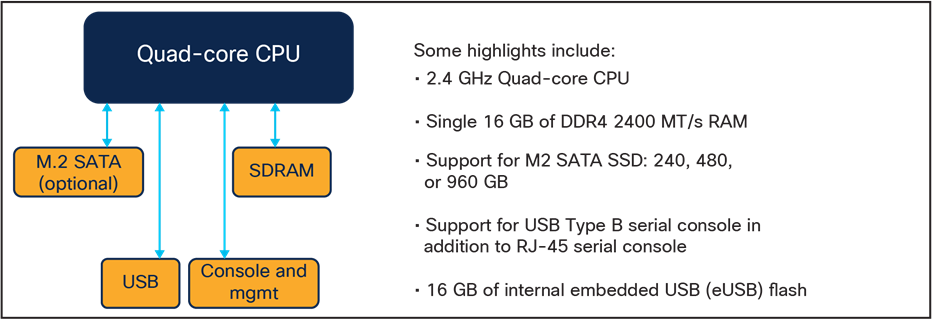
x86 CPU quad core complex on Sup 1/1XL/1XL-Y
The Cisco Catalyst 9400 Series supervisors 2XL/2 are equipped with the same CPU, system memory, and flash storage (Figure 20).
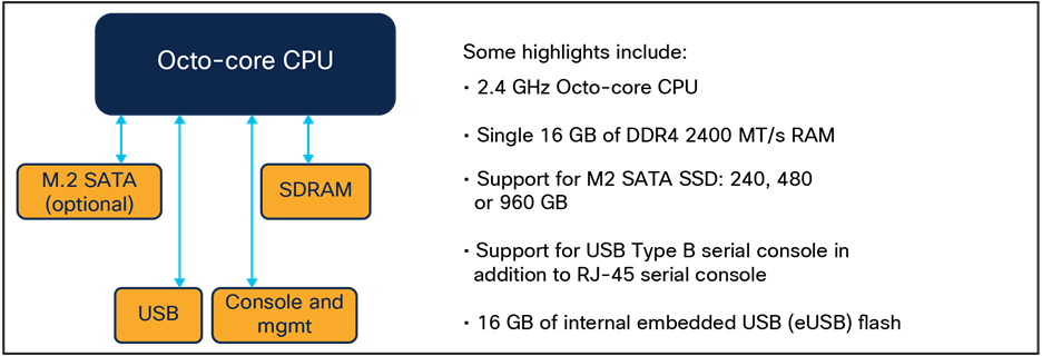
x86 CPU octo core complex on Sup 2XL/2
The Cisco Catalyst 9400 Series Supervisors 1/1XL/1XL-Y are built with three UADP 2.0 XL ASICs (Figure 21). Communication within a core or between cores is locally switched within the ASIC. So, packets destined to local ports within the ASIC do not use the ASIC interconnect link. The purpose of the ASIC interconnect is to move data between multiple UADP ASICs.
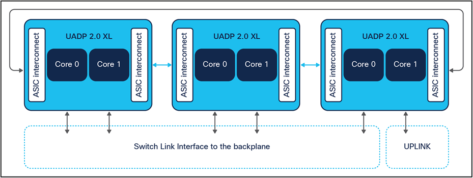
UADP 2.0 XL ASIC interconnect diagram
UADP 2.0 XL has effective bandwidth of 720 Gbps, with each core ASIC interconnect able to transfer up to 360 Gbps. The 360-Gbps bandwidth is composed of six dual independent 60-Gbps rings.
The Cisco Catalyst 9400 Series Supervisors 2XL/2 are built with three UADP 3.0sec ASICs (Figure 22). Communication within a core or between cores is locally switched within the ASIC. So, packets destined to local ports within the ASIC do not use the ASIC interconnect link. The ASIC interconnect is changed to use Directly Connected Point to Point links with 1.6Tbps bandwidth to move data between UADP ASICs.
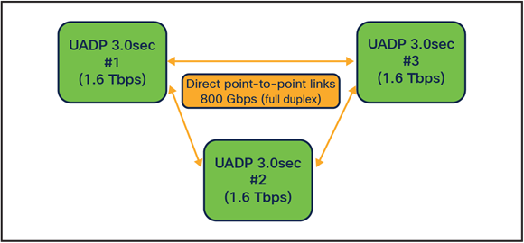
UADP 3.0sec ASIC interconnect diagram
Ethernet PHY (physical layer) connects a link layer device (often a MAC) to a physical medium such as a transceiver. PHY on Cisco Catalyst 9400 Series switches is a fully integrated Ethernet transceiver supporting steering and mapping of lanes back to the stub ASIC on the line card. The PHY chip offers support for multiple speeds (10/100 Mbps, 1, 10, 25, 40 and 100 Gbps), depending on the optics inserted on the front panel ports or if copper ports are present.
Figure 23 summarizes the mix of ports on a single supervisor Sup-1/1XL/1XL-Y.
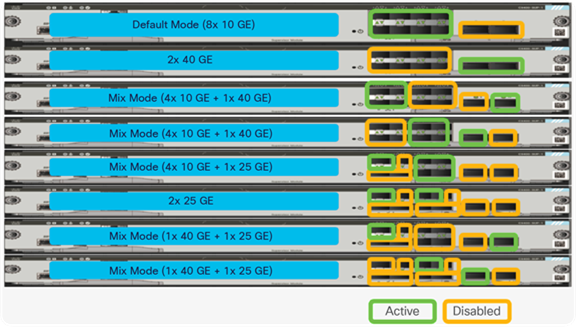
Single supervisor SUP1/1XL/1XL-Y uplink options
● The system can support two 40-Gbps ports or two 25-Gbps ports or eight 10-Gbps ports.
● The system can support any mix of 40-Gbps, 25-Gbps, and 10-Gbps ports if the total uplink bandwidth does not exceed 80 Gbps (2 port groups x 40 Gbps), where one port group can operate in 4x1/10 Gbps, 1x 40 Gbps or 1x25 Gbps.
Figure 24 summarizes the mix of ports on dual supervisor Sup-1/1XL/1XL-Y.
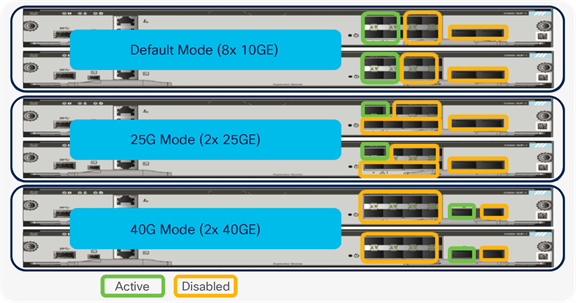
Dual supervisor Sup-1/1XL/1XL-Y uplink options
● The system can support two 40-Gbps ports or two 25-Gbps ports or eight 10-Gbps ports. It is recommended to use at least one port per supervisor card.
● The system can support any mix of 40-Gbps, 25-Gbps, or 10-Gbps ports if the total uplink bandwidth does not exceed 80 Gbps (2 port groups x 40 Gbps) between the two supervisors, where one port group can operate in 4x1/10 Gbps, 1x 40 Gbps or 1x25 Gbps. The above diagram does not show all combinations.
● When the system uses dual supervisor mode, only the first port groups from each supervisor can be used. In that mode the active supervisor controls the links on that standby supervisor which delivers 80 Gbps uplink throughput even if the standby Supervisor reloads or stateful switchover happens.
Figure 25 summarizes the mix of ports on a single supervisor Sup-2XL/2.
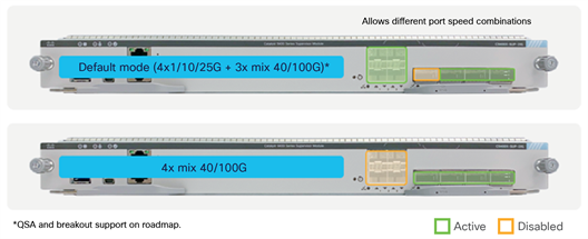
Single supervisor Sup-2XL/2 uplink options
● 4x 40/100G.
● 4x 1/10/25G + 3x 100G.
Figure 26 summarizes the mix of ports on dual supervisor Sup-2XL/2.
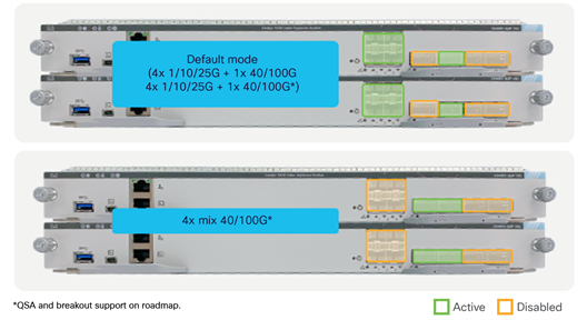
Dual supervisor Sup-2XL/2 uplink options
● 4x 1/10/25G + 1x 40/100G.
● 4x 40/100G.
Figure 27 Shows the architecture the C9400-LC-48U and C9400-LC-48H line cards.
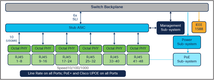
Diagram for C9400-LC-48/U (PoE+/ Cisco UPOE) and C9400-LC-48H (PoE+/UPOE/UPOE+) line card
● The PHY ports are connect to a stub ASIC. The stub ASIC is used to aggregate the PHY connections and provide connection to the chassis backplane interface.
● The stub ASIC does not participate in packet processing.
● The module offers 48x 10/100/1000 Mbps ports with PoE+ and Cisco UPOE inline power.
● C9400-LC-48H line card can provide IEEE 802.3bt up to 90 W for up to 260 ports from 384 on C9410R, and fully loaded 90W on C9407R/C9404R.
Figure 28 Shows the architecture the C9400-LC-24S/48S and C9400-LC-48T line cards.
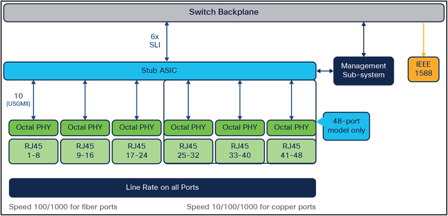
Diagram for C9400-LC-24S/48S and C9400-LC-48T line cards
● The PHY ports are connect to a stub ASIC. The stub ASIC is used to aggregate the PHY connections and provide connection to the chassis backplane interface.
● The stub ASIC does not participate in packet processing.
● The modules do not offer inline power.
● The C9400-LC-48T line card provides 48x 10/100/1000 Mbps copper ports.
● The C9400-LC-24S/48S line card provides 24x/48x 100/1000 Mbps fiber ports.
Figure 29 Shows the architecture the C9400-LC-24XS line card.
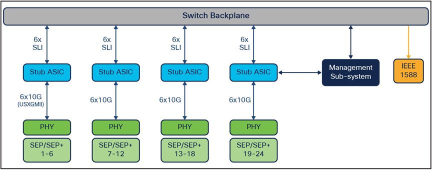
Diagram for the C9400-LC-24XS line card
● The PHY ports are connect to a stub ASIC. The stub ASIC is used to aggregate the PHY connections and provide connection to the chassis backplane interface.
● The stub ASIC does not participate in packet processing.
● The module does not offer inline power.
● The C9400-LC-24XS line card provides 24x 1/10 Gbps fiber ports.
● When the module is used with the C9404R chassis, there are no port groups.
Figure 30 shows the allocated port groups when the module is used with the C9407R or C9410R chassis.
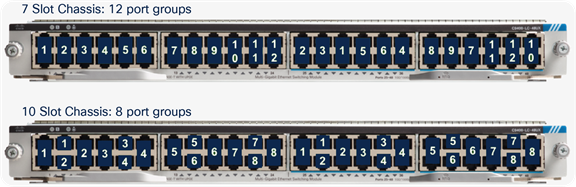
Port groups for the C9407R and C9410R chassis with the C9400-LC-24XS module
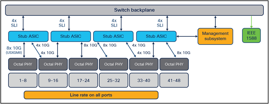
Figure 31 Shows the architecture the C9400-LC-48UX line card.
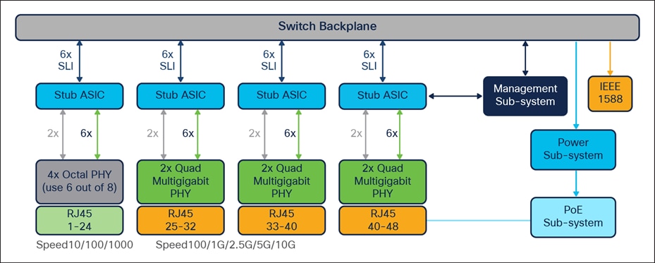
Diagram for the C9400-LC-48UX line card
● The PHY ports are connect to a stub ASIC. The stub ASIC is used to aggregate the PHY connections and provide connection to the chassis backplane interface.
● The stub ASIC does not participate in packet processing.
● The module offers PoE+/UPoE inline power.
● The C9400-LC-48UX line card provides 24x 10/100/1000 Mbps copper ports and 24x 100/1G/2.5G/5G/10G copper ports (for 10 Gbps, use Cat6a or Cat7).
● When the module is used with the C9404R chassis, there are no port groups.
Figure 32 shows the allocated port groups when the module is used with the C9407R or C9410R chassis.
Port groups for the C9407R and C9410R chassis with the C9400-LC-48UX module
Figure 33 Shows the architecture the C9400-LC-48HN line card.
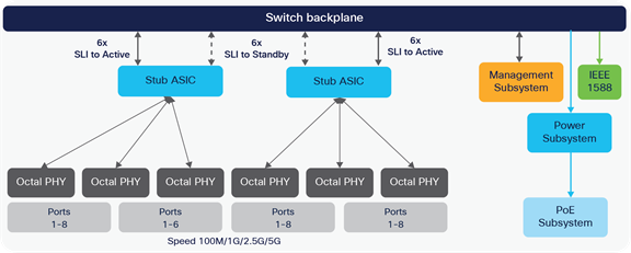
Diagram for the C9400-LC-48HN line card
● The PHY ports are connect to a stub ASIC. The stub ASIC is used to aggregate the PHY connections and provide connection to the chassis backplane interface.
● The stub ASIC does not participate in packet processing.
● The module offers PoE+/UPOE/UPOE+/802.3bt Type 1-4 inline power.
● The C9400-LC-48HN line card provides 48x 100/1G/2.5G/5G copper ports.
● C9400-LC-48HN line card can provide IEEE 802.3bt up to 90 W for up to 240 ports from 384 on C9410R, and fully loaded 90W on C9407R/C9404R.
Figure 34 shows the allocated port groups when the module is used with the C9407R or C9410R chassis.
Port groups for the C9404R, C9407R and C9410R chassis with the C9400-LC-48HN module
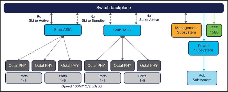
Figure 35 Shows the architecture the C9400-LC-48HX line card.
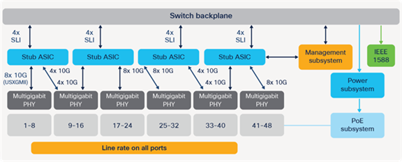
Diagram for the C9400-LC-48HX line card
● The PHY ports are connect to a stub ASIC. The stub ASIC is used to aggregate the PHY connections and provide connection to the chassis backplane interface.
● The stub ASIC does not participate in packet processing.
● The module offers PoE+/UPOE/UPOE+/802.3bt Type 1-4 inline power.
● The C9400-LC-48HX line card provides 48x 100/1G/2.5G/5G/10G copper ports.
● C9400-LC-48HX line card can provide IEEE 802.3bt up to 90 W for up to 224 ports from 384 on C9410R, up to 226 ports out of 240 on C9407R and fully loaded 90W on C9404R.
● The line card is supported only with Sup2XL and Sup2
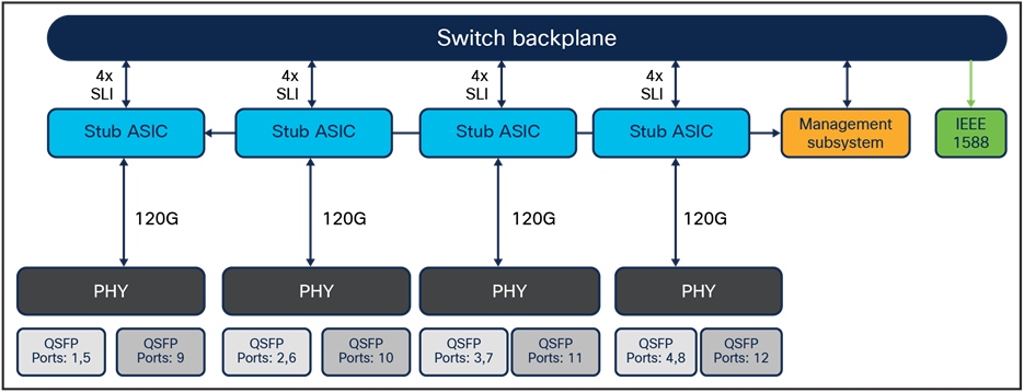
Figure 36 Shows the architecture the C9400-LC-48XS line card.
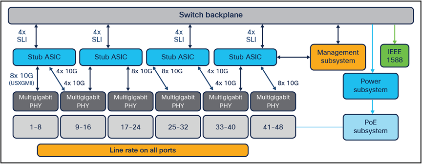
Diagram for the C9400-LC-48XS line card
● The PHY ports are connect to a stub ASIC. The stub ASIC is used to aggregate the PHY connections and provide connection to the chassis backplane interface.
● The stub ASIC does not participate in packet processing.
● The C9400-LC-48XS line card provides 48x 1G/10G fiber ports.
● The line card is supported only with Sup2XL and Sup2
Supported line cards per Supervisor
Figure 37 shows supported line cards per Supervisor
Supported line cards per Supervisor
Cisco Catalyst 9400 Series Switches provides two types for external storages:
1. USB 3.0 SSD on the front-panel of the Supervisors (up to 120G)
2. M2 Serial Advanced Technology Attachment (SATA) that can be plugged into the removable Supervisor (up to 1TB)
These external storages can be used for general-purpose storage for packet capture, operation system trace logs, and Graceful Insertion and Removal (GIR) snapshots. Mostly importantly, they can be used for application hosting. An application, hosted on a network device, can serve a variety of purpose. This ranges from automation, configuration management monitoring, and integration with exiting tool chains.
Cisco Catalyst 9400 Series switches use the Cisco Application Framework, also known as Cisco IOx (the application framework combines Cisco IOS and Linux), to support containerized applications in Docker Containers. The switch can provide dedicated memory and CPU resources for application hosting. By reserving memory and CPU resources, the switch provides a separate execution space for third-party applications, protecting the switch’s Cisco IOS XE run-time processes and helping ensure its integrity and performance. Application hosting is only supported on M2 SATA drive storage inside of the Supervisor.
Internal flash storage cannot be used to store third-party application(s) as it is not supposed to be formatted as EXT2 or EXT4 file system. But the external storage can support EXT2 or EXT4(default) file systems and application hosting. Also, it has ability to monitor the health of the SSD storage through S.M.A.R.T.
This section provides a high-level overview of how packet forwarding is performed on the Cisco Catalyst 9400 Series Switches. The packet walk described below is the same for all Cisco Catalyst 9400 Supervisors based on UADP 3.0sec and 2.0 XL.
Ingress and egress unicast forwarding within the ASIC
Figure 38 shows the basic sequence of events when packets enter the Cisco Catalyst 9400 Series front panel ports for unicast packet forwarding within the ASIC.
Unicast packet walk within single ASIC Core
1. Packet arrives at ingress port; PHY converts the signal and serializes the bits, and then sends the packet to the Network Interface (NIF) on the ASIC.
2. NIF passes packet to ingress MACsec engine. The NIF also implements 1588 timestamping and EEE if enabled.
3. MACsec engine is fixed-latency cryptography engine to support 802.1AE MAC Security and core cryptography of Layer 2 input frames that go to the ingress FIFO. It decrypts the packet if needed at line rate.
4. Ingress FIFO makes two frame copies and sends one to IFC and the other one to PBC in parallel.
5. IFC performs L2, L3, ACL, QoS Lookups and more to return forwarding result (frame descriptor header) to PBC.
6. PBC is the primary packet store on the UADP ASIC and holds the packet until forwarding decision from IFC come; Once the forwarding decision comes the packet is kept into PBC if the egress port is on same core or send over Core Interconnect link to the peer Core. Start Egress processing which includes: Egress Queues and Scheduler (EQS) is responsible for queue management, replication if needed, and scheduling packets. It enqueues packets arriving from the local ingress path into the egress queue structures and then schedules them for transmission to the corresponding egress ports. Then packet header is sent for processing at Egress Forwarding Controller (EFC).
7. EFC completes egress lookup functions (such as egress switched port analyzer [SPAN], Security ACL, QoS remarking/policing, recirculation and more) and sends the final rewrite descriptor to the RWE.
8. RWE performs packet rewrite with the final descriptor and sends the packet to the egress port FIFO, which provides storage for frames awaiting transmission to either the NIF or the recirculation path.
9. Egress MACsec performs a wire-rate encryption if required by the frame for 802.1AE and then passes the frame on to the NIF. Packet is ready to leave the ASIC and be sent out by the port.
Ingress and egress unicast forwarding across ASICs
Figure 39 shows the basic sequence of events when unicast packets enter the Cisco Catalyst 9400 Series front panel ports and is sent across the ASIC interconnect link.
Unicast packet walk across ASICs
10. Packet arrives at ingress port; PHY converts the signal and serializes the bits, and then sends the packet to the Network Interface (NIF) on the ASIC.
11. NIF passes packet to ingress MACsec engine. The NIF also implements 1588 timestamping and EEE if enabled.
12. MACsec engine is fixed-latency cryptography engine to support 802.1AE MAC Security and core cryptography of Layer 2 input frames that go to the ingress FIFO. It decrypts the packet if needed at line rate.
13. Ingress FIFO makes two frame copies and sends one to IFC and the other one to PBC in parallel.
14. IFC performs L2, L3, ACL, QoS Lookups and more to return forwarding result (frame descriptor header) to PBC.
15. PBC is the primary packet store on the UADP ASIC and holds the packet until forwarding decision from IFC come; Once the forwarding decision comes the packet will be sent over ASIC interconnect link but first it will go to Ingress Queue Scheduling (IQS) block which queues the packets to the stack link.
16. IQS performs queuing and managing congestion to the stack interface.
17. PBC enqueue the packet to the stack interface based on its priority.
18. PBC on Egress ASIC receives the packet and start egress processing into Egress Queues and Scheduler (EQS).
19. EQS is responsible for queue management, replication if needed, and scheduling packets. It enqueues packets arriving from the local ingress path into the egress queue structures and then schedules them for transmission to the corresponding egress ports. Then packet header is sent for processing at Egress Forwarding Controller (EFC).
20. EFC completes egress lookup functions (such as egress switched port analyzer [SPAN], Security ACL, QoS remarking/policing, recirculation and more) and sends the final rewrite descriptor to the RWE.
21. RWE performs packet rewrite with the final descriptor and sends the packet to the egress port FIFO, which provides storage for frames awaiting transmission to either the NIF or the recirculation path.
22. Egress MACsec performs a wire-rate encryption if required by the frame for 802.1AE and then passes the frame on to the NIF. Packet is ready to leave the ASIC and be sent out by the port.
Cisco Catalyst 9400 Series switches are enterprise-class access and distribution switches in the Cisco Catalyst 9000 family, offering a comprehensive portfolio and architectural flexibility with 1/10 Gbps downlink ports and 10/25/40/100 Gbps uplink ports. This new platform is based on Cisco’s next-generation programmable UADP ASIC for increased bandwidth, scale, security, and telemetry. The platform also supports infrastructure investment protection with nondisruptive migration from 10 Gbps to 25 Gbps and beyond. The Cisco Catalyst 9400 Series is built on a modular system architecture designed to provide high performance to meet the evolving needs of highly scalable and growing enterprise networks.
The following websites offer more details on the Cisco Catalyst 9400 Series and its capabilities.
Cisco Catalyst 9400 Series Switches Data Sheet
Cisco Catalyst 9400 Series Switches Hardware Installation Guide
Cisco Catalyst 9400 Supervisor Engine-1 Data Sheet
Cisco Catalyst 9400 Supervisor Engine-2 Data Sheet
Cisco Catalyst 9400 Series Line Cards Data Sheet
Cisco Catalyst 9000 - Switching for a New Era of Intent-based Networking
25GE and 100GE – Enabling Higher Speeds in Enterprise with Investment Protection White Paper