Cisco Catalyst 9300 Series Switches Architecture White Paper
Available Languages
Bias-Free Language
The documentation set for this product strives to use bias-free language. For the purposes of this documentation set, bias-free is defined as language that does not imply discrimination based on age, disability, gender, racial identity, ethnic identity, sexual orientation, socioeconomic status, and intersectionality. Exceptions may be present in the documentation due to language that is hardcoded in the user interfaces of the product software, language used based on RFP documentation, or language that is used by a referenced third-party product. Learn more about how Cisco is using Inclusive Language.
Enterprise campus networks are undergoing profound changes to support ever-increasing bandwidth demands on the access layer, heightened by the introduction of the 802.11ac and 802.11ax standards and the rapid growth of powerful endpoints requiring speeds from 10 Mbps to 10 Gbps. These networks are in dire need of an infrastructure that can scale rapidly and accommodate the new breed of endpoints without the need to replace the complete cabling infrastructure.
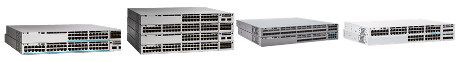
Cisco® Catalyst® 9300 Series Switches are the foundation of Cisco’s next-generation enterprise-class access layer solutions. These fixed, stackable switches are available in various configurations, including data, Universal Power over Ethernet (UPoE), and Multigigabit models. They deliver exceptional table scales (MAC/route/ACL) and buffering capabilities for enterprise applications. The Cisco Catalyst 9300 Series platform delivers up to 1760 Gbps of switching capacity in standalone mode and 14 Tbps when stacked as eight-member switches, with up to 3.8 Billion packets per second (Bpps) of forwarding performance. The platform’s stacking capability provides a flexible, pay-as-you-grow model as well as simplicity in the ability to manage multiple switches as a single logical switch. The switches provide four kinds of models for different access layer requirements. One provides nonblocking 1 Gigabit Ethernet over Cisco Universal Power over Ethernet (Cisco UPOE® and UPOE+®) capable copper ports with additional support for 10- and 100-Mbps speeds. The second one supports nonblocking Multigigabit speeds varying from 100 Mbps to 1, 2.5, 5, and 10 Gbps over Cisco UPOE/UPOE+ capable copper port switches. The third one supports nonblocking 1, 10, 25 Gbps over the fiber ports. The platform also offers optional uplink modules that support nonblocking 100 Gigabit Ethernet (100G) Quad Small Form-Factor Pluggable (QSFP+),40 Gigabit Ethernet (40G) Quad Small Form-Factor Pluggable (QSFP+), 25G Small Form-Factor Pluggable 28 (SFP28),10G Enhanced Small Form-factor Pluggable (SFP+), and 1G Small Form-Factor Pluggable (SFP) to meet diverse campus needs when connecting to aggregation or core devices. The fourth one supports nonblocking Multigigabit speeds varying from 100 Mbps to 1, 2.5, 5, and 10 Gbps over Cisco UPOE capable copper port switches in shallow form factor of less than 13.2 inches in depth with fixed uplink modules.
This white paper provides an architectural overview of the Cisco Catalyst 9300 Series chassis, including system design, power, cooling, and storage options.
The Cisco Catalyst 9300 Series platform consists of fixed-configuration switches with airflow from the front and sides to the back. They are based on the Cisco Unified Access® Data Plane 2.0 (UADP) architecture, which not only protects your investment but also allows a larger scale and higher throughput. The platform runs on the open Cisco IOS® XE operating system, which supports model-driven programmability, and has the capacity to host containers, with support for up to 240 GB of SSD storage. It can also run third-party applications and scripts natively within the switch (by virtue of the x86 CPU architecture, local storage, and a higher memory footprint). The modern operating system offers enhanced high availability features such as Extended Fast Software Upgrade (xFSU), Stateful Switchover (SSO), Software Maintenance Upgrades (SMU), Graceful Insertion and Removal (GIR), Cisco StackWise® and StackPower technology. Further, it supports all the foundational high-availability capabilities, including Platinum-efficient dual redundant power supplies and variable-speed, high-efficiency, redundant fans.
The Cisco Catalyst 9300 Series consist of Modular Uplink Models and Fixed uplink models with variable port speeds and port densities to meet the ever-increasing performance demands of enterprise campus environments and provide an architectural foundation for next-generation hardware features and scalability.
1G and Multigigabit switches
Data-only switches
C9300-24T - Cisco Catalyst 9300 Series Switch 1xUADP 2.0 ASIC with 24x 10M/100M/1G Ethernet ports with optional uplink modules.
C9300-48T - Cisco Catalyst 9300 Series Switch 1xUADP 2.0 ASIC with 48x 10M/100M/1G Ethernet ports with optional uplink modules.
PoE+ switches
C9300-24P - Cisco Catalyst 9300 Series Switch 1xUADP 2.0 ASIC with 24x 10M/100M/1G Ethernet Ports with optional uplink modules.
C9300-48P - Cisco Catalyst 9300 Series Switch 1xUADP 2.0 ASIC with 48x 10M/100M/1G Ethernet Copper ports with optional uplink modules.
Cisco UPOE switches
C9300-24U - Cisco Catalyst 9300 Series Switch 1xUADP 2.0 ASIC with 24x 10M/100M/1G Ethernet Copper ports with optional uplink modules.
C9300-48U - Cisco Catalyst 9300 Series Switch 1xUADP 2.0 ASIC with 48x 10M/100M/1G Ethernet Copper ports with optional uplink modules.
C9300-24UB - Cisco Catalyst 9300 Series Switch 1xUADP 2.0 XL ASIC with 24x 10M/100M/1G Ethernet Copper ports with optional uplink modules.
C9300-48UB - Cisco Catalyst 9300 Series Switch 1xUADP 2.0 XL ASIC with 48x 10M/100M/1G Ethernet Copper ports with optional uplink modules.
Cisco UPOE+ switches
C9300-24H - Cisco Catalyst 9300 Series Switch 1xUADP 2.0 ASIC with 24x 10M/100M/1G Ethernet Copper ports with optional uplink modules.
C9300-48H - Cisco Catalyst 9300 Series Switch 1xUADP 2.0 ASIC with 48x 10M/100M/1G Ethernet Copper ports with optional uplink modules.
Multigigabit Ethernet switches with Cisco UPOE and UPOE+
C9300-24UX - Cisco Catalyst 9300 Series 2xUADP 2.0 ASIC with 24x 100M/1G/2.5G/5G/10G Ethernet Copper ports with optional Uplink Modules.
C9300-24UXB - Cisco Catalyst 9300 Series 2xUADP 2.0 XL ASIC with 24x 100M/1G/2.5G/5G/10G Ethernet Copper ports with optional Uplink Modules.
C9300X-24HX - Cisco Catalyst 9300 Series 2xUADP 2.0sec ASIC with 24x 100M/1G/2.5/5/10G Copper ports with optional uplink modules.
C9300-48UXM - Cisco Catalyst 9300 Series 2xUADP 2.0 ASIC with 36x 100M/1G/2.5G Copper ports and 12x 100M/1G/2.5G/5G/10G Ethernet Copper ports with optional uplink modules.
C9300-48UN - Cisco Catalyst 9300 Series 2xUADP 2.0 ASIC with 48x 100M/1G/2.5G/5G Copper ports and with optional uplink modules.
C9300X-48HX - Cisco Catalyst 9300 Series 2xUADP 2.0sec ASIC with 48x 100M/1G/2.5/5/10G Copper ports and with optional uplink modules.
C9300-48HXN - Cisco Catalyst 9300 Series 2xUADP 2.0sec ASIC with 36x 100M/1G/2.5G Copper ports and 12x 100M/1G/2.5G/5G/10G Ethernet Copper ports with optional uplink modules.
Cisco 1G SFP switches
C9300-24S - Cisco Catalyst 9300 Series 1xUADP 2.0 ASIC with 24x 1G SFP ports with optional Uplink Modules.
C9300-24S - Cisco Catalyst 9300 Series 1xUADP 2.0 XL ASIC with 24x 1G SFP ports with optional Uplink Modules.
10/25G switches
Fiber switches
C9300X-12Y - Cisco Catalyst 9300 Series Switch 1xUADP 2.0sec ASIC with 12x 10M/100M/1G/10G/25G Ethernet ports with optional uplink modules.
C9300X-24Y - Cisco Catalyst 9300 Series Switch 2xUADP 2.0sec ASIC with 48x 10M/100M/1G/10G/25G Ethernet ports with optional uplink modules.
1G switches
Data-only switches
C9300L-24T-4G - Cisco Catalyst 9300 Series Switch 1xUADP 2.0 ASIC with 24x 10M/100M/1G Ethernet ports with 4x 1G fixed uplinks
C9300L-24T-4X - Cisco Catalyst 9300 Series Switch 1xUADP 2.0 ASIC with 24x 10M/100M/1G Ethernet ports with 4x 10G fixed Uplinks
C9300L-48T-4G - Cisco Catalyst 9300 Series Switch 1xUADP 2.0 ASIC with 48x 10M/100M/1G Ethernet ports with 4x 1G fixed uplinks
C9300L-48T-4X - Cisco Catalyst 9300 Series Switch 1xUADP 2.0 ASIC with 48x 10M/100M/1G Ethernet ports with 4x 10G fixed uplinks
C9300LM-48T-4Y- Cisco Catalyst 9300 Series Switch 1xUADP 2.0 ASIC with 48x 10M/100M/1G Ethernet ports with 4x 25G fixed uplinks
PoE+ switches
C9300L-24P-4G - Cisco Catalyst 9300 Series Switch 1xUADP 2.0 ASIC with 24x 10M/100M/1G Ethernet Ports with 4x 1G fixed uplinks.
C9300L-24P-4X - Cisco Catalyst 9300 Series Switch 1xUADP 2.0 ASIC with 24x 10M/100M/1G Ethernet Ports with 4x 10G fixed uplinks.
C9300L-48P-4G - Cisco Catalyst 9300 Series Switch 1xUADP 2.0 ASIC with 48x 10M/100M/1G Ethernet Copper ports with 4x 1G fixed uplinks.
C9300L-48P-4X - Cisco Catalyst 9300 Series Switch 1xUADP 2.0 ASIC with 48x 10M/100M/1G Ethernet Copper ports with 4x 10G fixed uplinks.
UPOE/Mgig-only switches
C9300L-24UXG-4X - Cisco Catalyst 9300 Series Switch 2xUADP 2.0 ASIC with 8x 100M/1G/2.5G/5G/10G, 16x 10M/100M/1G Ethernet Copper ports with 4x 10G fixed uplinks.
C9300L-24UXG-2Q - Cisco Catalyst 9300 Series Switch 2xUADP 2.0 ASIC with 8x 100M/1G/2.5G/5G/10G, 16x 10M/100M/1G Ethernet Copper ports with 2x 40G fixed uplinks.
C9300L-48UXG-4X - Cisco Catalyst 9300 Series Switch 2xUADP 2.0 ASIC with 12x 100M/1G/2.5G/5G/10G, 36x 10M/100M/1G Ethernet Copper ports with 4x 10G fixed uplinks.
C9300L-48UXG-4Q - Cisco Catalyst 9300 Series Switch 2xUADP 2.0 ASIC with 12x 100M/1G/2.5G/5G/10G, 36x 10M/100M/1G Ethernet Copper ports with 2x 40G fixed uplinks.
C9300LM-24U-4Y - Cisco Catalyst 9300 Series Switch 1xUADP 2.0 ASIC with 24x 10M/100M/1G Ethernet Copper ports with 4x 25G fixed uplinks.
C9300LM-48U-4Y - Cisco Catalyst 9300 Series Switch 1xUADP 2.0 ASIC with 48x 10M/100M/1G Ethernet Copper ports with 4x 25G fixed uplinks.
C9300LM-48UX-4Y - Cisco Catalyst 9300 Series Switch 1xUADP 2.0 ASIC with 8x 100M/1G/2.5G/5G/10G, 40x 10M/100M/1G Ethernet Copper ports with 4x 25G fixed uplinks.
This section briefly describes the highlights of the Cisco Catalyst 9300 Series chassis.
Multiple SKU options: Select the system that best fits based on port speed, port density, and network scale.
Up to two “Platinum-efficiency” 350W,600W 715W, 1000W,1100W or 1900W AC and 715W DC power supplies. The Cisco Catalyst 9300 Series can support 1:1 power redundancy and 1+N redundancy with the StackPower feature.
New 24,000-rpm high-efficiency fans with N+1 redundancy.
120/240-GB external SSD storage, enabling application hosting capability on Cisco Catalyst switches for the first time.
This section briefly covers the high-level system design of the Cisco Catalyst 9300 Series. A distributed architecture is used for all 9300 models. The architecture offers option to combine up to eight physical switches as one logical switch using Cisco StackWise® technology.
Figures 1, 2, and 3 show the different board layouts.

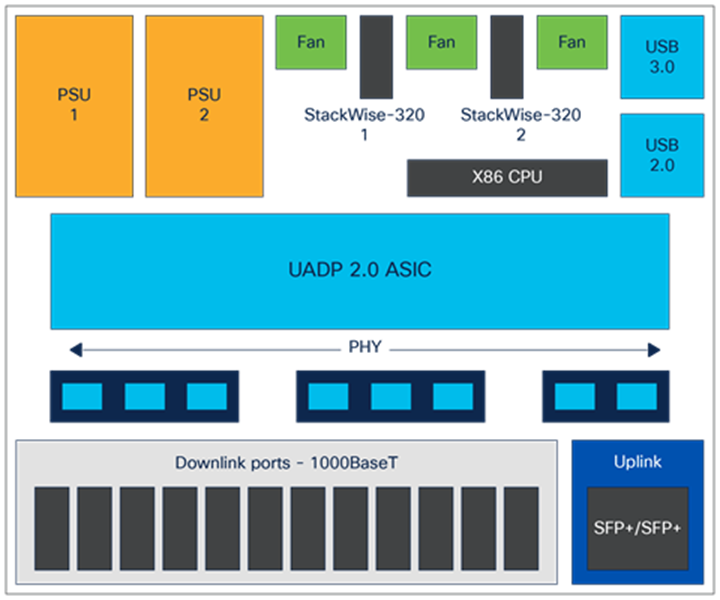
C9300-24T/48T/24S/48S board layout

C9300-24P/48P/24U/48U/24UB/48UB/24H/48H board layout
C9300-24UX/48UXM/48UN/24UXB board layout

C9300X-48HX
C9300X-24Y
C9300X-24HX/48HXN
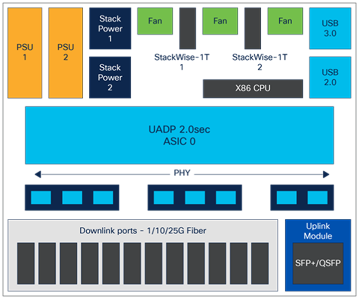
C9300X-12Y
C9300L-24T-4G/48T-4G/24T-4X/48T-4X
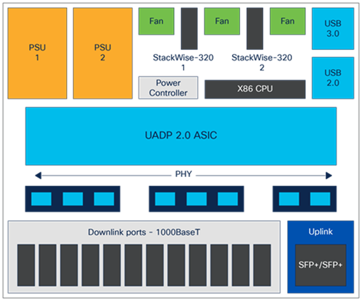
C9300L-24P-4G/48P-4G/24P-4X/48P-4X
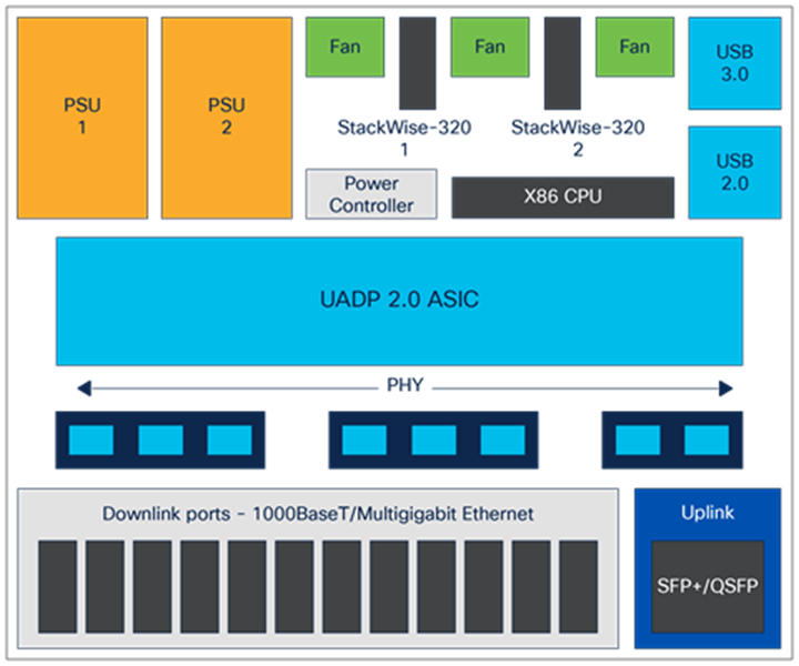
C9300L-24UXG-4X/24UXG-2Q/48UXG-4X/48UXG-2Q

C9300LM-24U/48U/48T-4Y

C9300LM-48UX-4Y
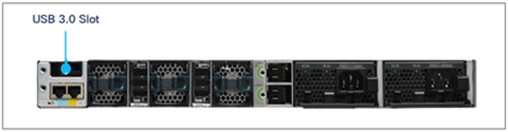
The Cisco Catalyst 9300 Series Switches come with two field-replaceable Power Supply Unit (PSU) slots and support AC or DC power inputs. There are three redundant variable-speed fans in the back of the switch. All 9300 Series models come with a built-in passive RFID for inventory management, a Blue Beacon LED for device-level identification, a tricolor LED for system status, a RJ-45 console port, 1G management port. and a USB 3.0 drive for storage purposes.
Catalyst 9300 non-X models also consist of two StackWise-480 and 9300X models consist of two StackWise-1T slots along with StackPower slots with built in stack adapters for high availability purpose. Catalyst 9300L models only come with two StackWise-320 slots with optional stack kit that consist of stack cables and connectors which has to be ordered separately. The front of the switch has a USB Type B connector for connecting a console to the switch and USB 2.0 host port for storage.
The Cisco Catalyst 9300 Series Switches support up to two 350W, 715W, 1100W or 1900W AC or 715W DC PSUs for a total POE capacity of Up to 1800W on UPoE and 2880W on UPOE+ models. PSU is rated as Platinum efficient for greater than 90 percent power efficiency at 100 percent load. The system supports either one PSU operating in nonredundant mode, which is sufficient to power the switch in its maximum configuration, or two PSUs operating in redundant load-sharing mode, where 50 percent power is withdrawn for each PSU. Power supplies support both AC, DC, and a combination of AC and DC units and support full Online Insertion and Removal (OIR) capabilities.
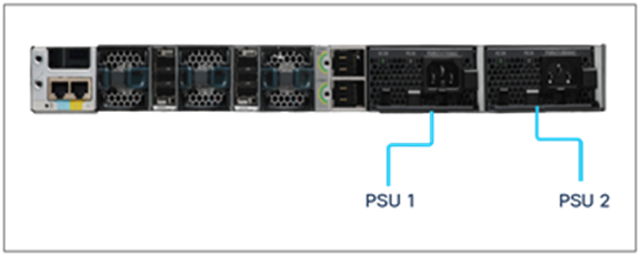
Numbering of power supplies
The maximum output power per power supply for the Cisco Catalyst 9300 Series is listed below. Each PSU has a power holdup time of approximately 20 milliseconds at 100 percent load. Each comes with front-to-back variable-speed cooling fans and has a push-release lock for simple and secure OIR.
● 1900W AC PSU is 1500W at 110V and 1900W at 220V input
● 1100W AC PSU is 1100W at 110V to 220V input
● 1000W AC PSU is 600W at 110V to 220V input(C9300LM only)
● 715W AC PSU is 715W at 110V to 220V input
● 600W AC PSU is 600W at 110V to 220V input(C9300LM only)
● 350W AC PSU is 350W at 110V to 220V input
● 715W DC PSU is 715W at 110V to 220V input
● 715W DC PSU is 715W at 110V to 220V input(C9300LM only)
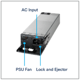
Power supply unit
Each PSU supports a bicolor (green/red) LED to show the status of the power supply.
Table 1. Meaning of AC PSU LED
| LED |
Color |
Status |
Description |
| AC |
|
Off |
No AC input power |
| AC |
|
On |
AC input power present |
| PS |
|
Off |
Output is disabled |
| PS |
|
On |
Power Output to switch active |
| PS |
|
Fail |
Output has failed |
The Cisco Catalyst 9300 Series Switches support hot-swappable and field-replaceable fans in the rear of the chassis. They are variable-speed, modular fans (three individual fan modules) supporting airflow from the front and sides to the back. The fan unit is responsible for cooling the entire chassis and interfacing with environmental monitors to trigger alarms when conditions exceed thresholds. The fan modules contain thermal sensors to detect ambient temperature and adjust the fan speed. The chassis supports a hardware failure of up to one individual fan or fan tray; the remaining fans will automatically increase their speed to compensate and maintain sufficient cooling. If the switch fails to meet the minimum number of required fans, the switch shuts down automatically to keep the system from overheating.
Cisco Catalyst 9300 Series chassis are equipped with on-board thermal sensors to monitor the ambient temperature at various points and report thermal events to the system so that it can adjust the fan speed.
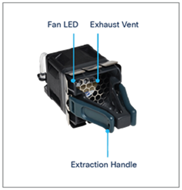
Fan module
Insertion and removal of the fan modules is made easy with fan assembly levers and ejectors. To remove the module, press the fan ejector lever and use the fan handle.
Table 2. Meaning of fan LED
| LED |
Color |
Status |
Description |
| Fan |
|
Solid |
Fan/Fans OK |
| Fan |
|
Solid |
Tachometer fault |
| Fan |
|
Solid |
One or more fans faulty (tachometer) Exceeded maximum limit |
The Cisco Catalyst 9300 Series fan supports airflow from the front and sides to the back.
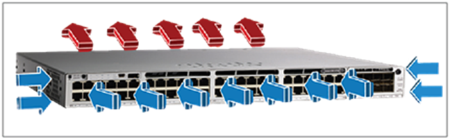
Airflow
The switch supports port-side and side intake airflow on all 9300 Series SKUs, in which coolant air enters the switch through the sides and ports (cold aisle) and exhausts through the fan and power supply modules in the rear (hot aisle).
The Cisco Catalyst 9300 Series Switches are line-rate switches that offer configurable system resources to optimize support for specific features, depending on how the switch is used in the network. The switch architecture consists of six main components:
● UADP Application-Specific Integrated Circuit (ASIC)
● x86 CPU complex
● ASIC interconnect
● StackWise-1T/480G/320G
● StackPower ports
● Front-panel interfaces
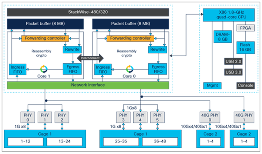
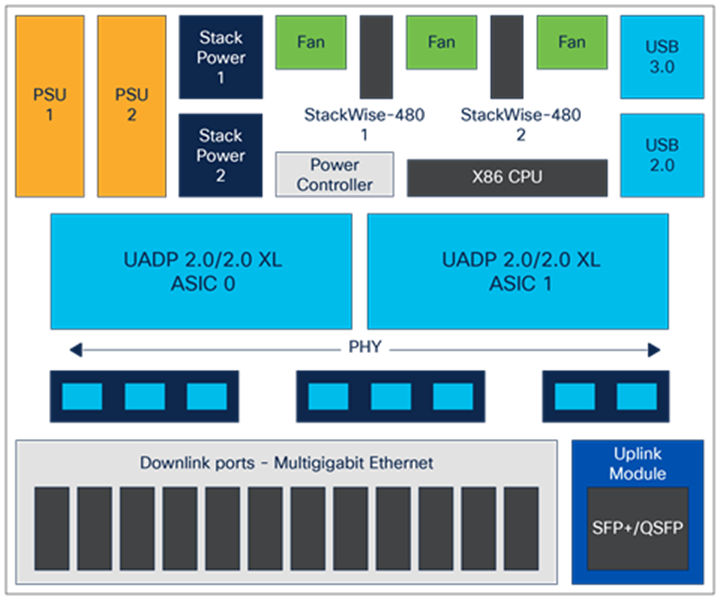
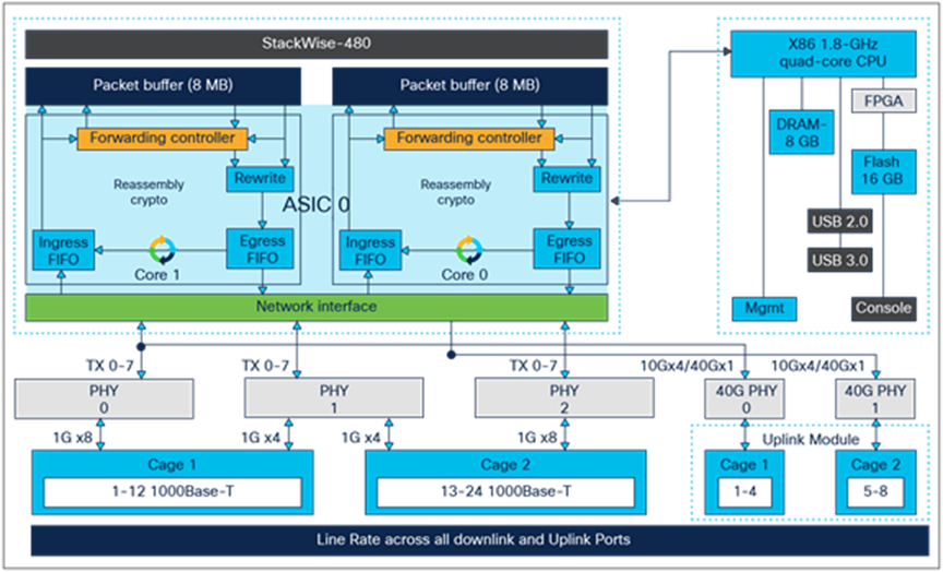
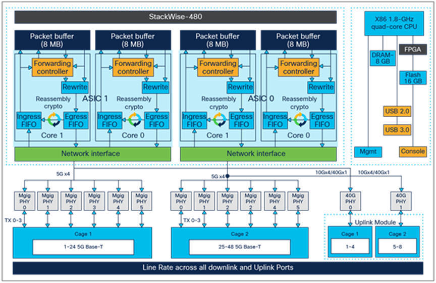
Cisco Catalyst 9300 Series high-level block diagram
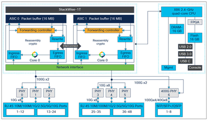
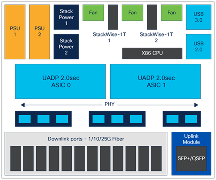
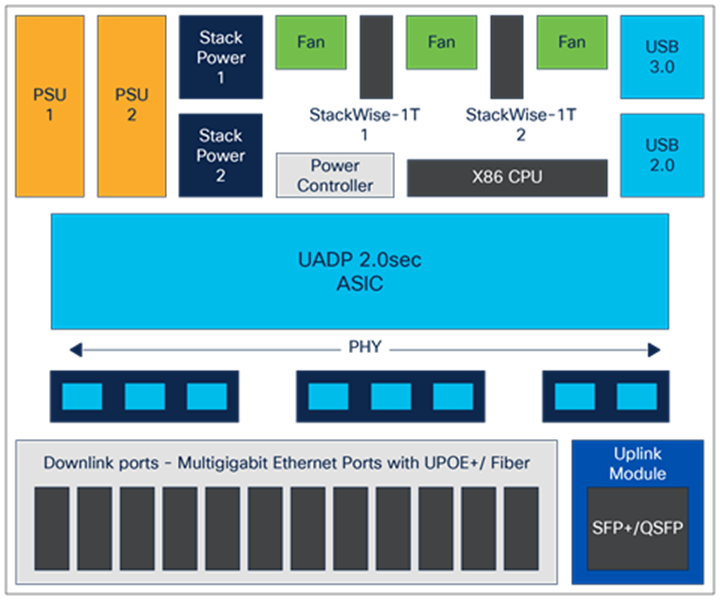
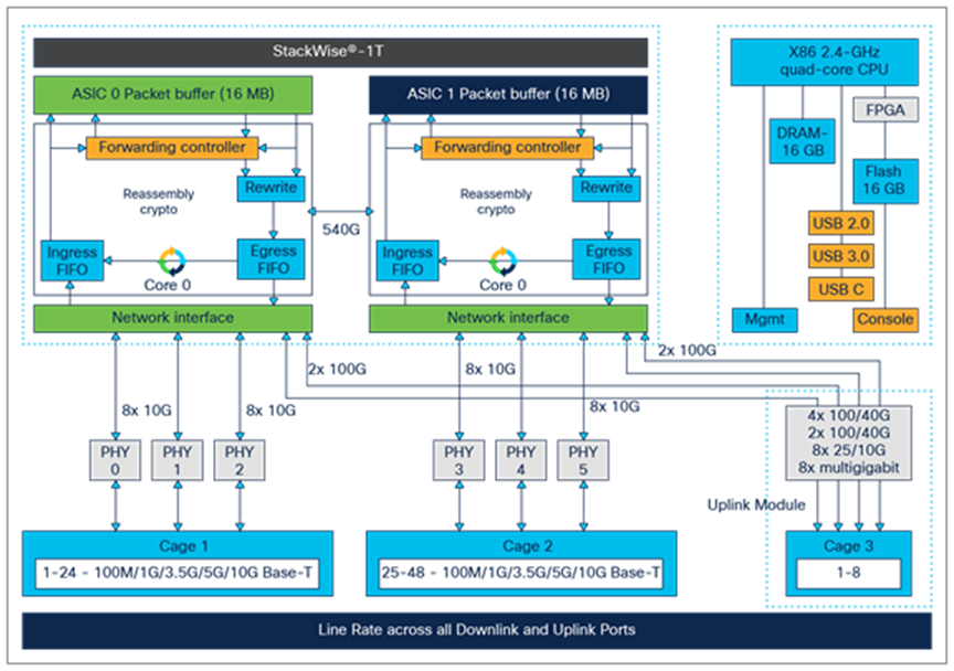
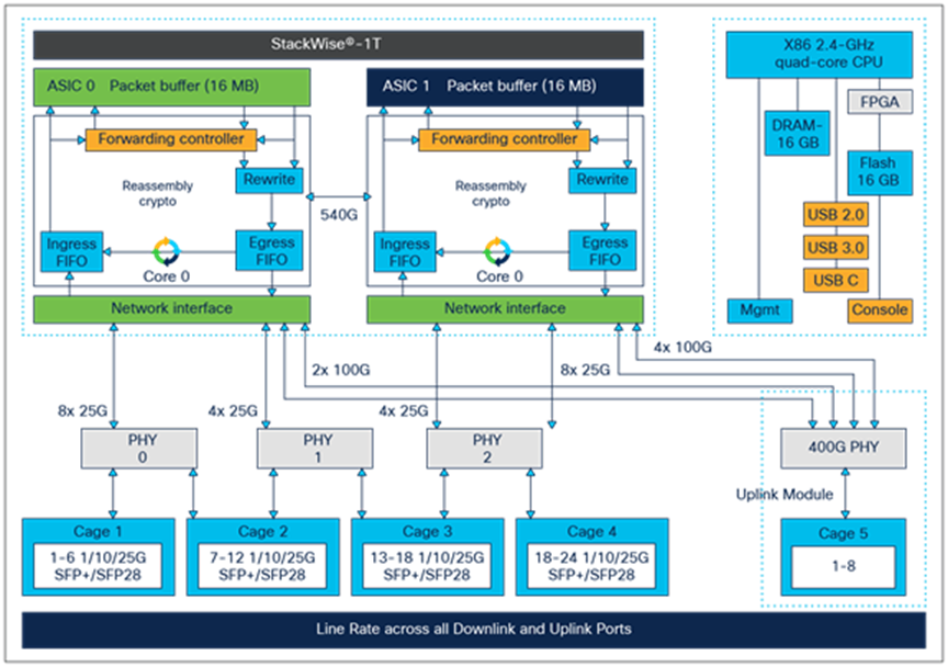
Cisco Catalyst 9300X Series high-level block diagram
The Cisco Catalyst 9300 Series is built with either UADP 2.0/ 2.0 XL or 2.0sec ASIC. C9300B models with UADP 2.0 XL version has higher switching capacity, memory and scale compared to C9300/C9300L non-XL version whereas C9300X models with UADP 2.0sec is focused on Security with a dedicated 100G encryption engine with higher switching capacity than XL asic but similar scale as non-XL asic. UADP 2.0 is the third generation of the UADP family which is based on System-On-Chip (SOC) architecture. It uses 28-nanometer technology and single/dual cores capable of switching either 160GB, 240GB or 500GB of data at line rate based on ASIC versions, and is specifically optimized for next-generation fixed access switches.
UADP 2.0 ASIC block diagram
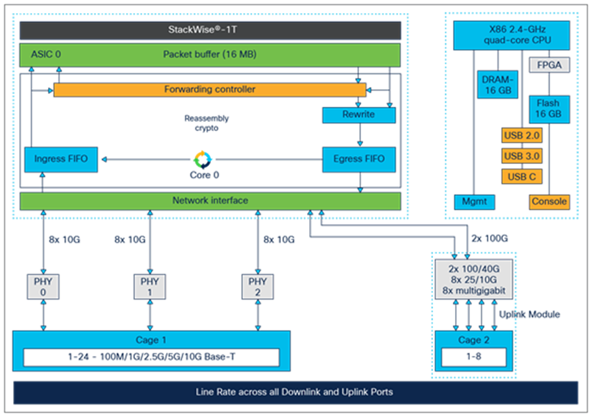
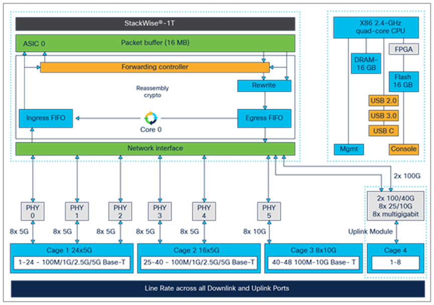
UADP 2.0sec ASIC block diagram
The architecture and functionality of UADP 2.0 family are largely unchanged from previous generations but there are some key differences. The key UADP 2.0/2.0XL/2.0sec capabilities are as follows:
● Packet bandwidth and switching throughput: 160G/240G (80G/120G per core) on 2.0/2.0XL and 500G on 2.0sec.
● Forwarding performance of 238 Mpps
● Stack bandwidth: 480/320 Gbps on 2.0/2.0XL and 1 Tbps on 2.0sec
● Forwarding Information Base (FIB) table: 32,000/16,000 IPv4/v6 direct attach and 8000/4000 IPv4/v6 longest prefix match entries on UADP 2.0; 39,000/19,500 IPv4/v6 direct attach and 15000/7500 IPv4/v6 longest prefix match entries on UADP 2.0sec
● Encryption Engine on UADP 2.0sec: 100G Dedicated Bandwidth for protocols like IPsec, etc.
● Packet buffer: 16/32 MB (8/16 MB per core) on UADP 2.0/2.0XL and 16MB on UADP 2.0sec (Single Core)
● Dedicated NetFlow block with 64,000/32,000 IPv4/v6 on UADP 2.0/2.0XL/2.0sec
● Security TCAM Access Control List (ACL) capacity: 5000/18000/8000 on UADP 2.0/2.0XL/2.0sec
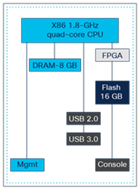
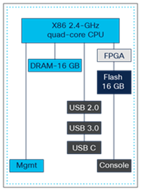
x86 CPU complex on C9300/9300L models and C9300X models
The Cisco Catalyst 9300 Series Switches are equipped with the similar x86 CPU specifications, system memory, and flash storage with some differences as shown in Figure 20 and highlighted below:
Highlights include:
● New 1.8/2.4-GHz x86 quad-core CPU
● Single 8/16 GB of DDR4 RAM
● Support for USB Type A file system (front serviceable) for external storage and Bluetooth dongle
● Support for USB Type B serial console in addition to the RJ-45 serial console
● Support for USB Type C connection on C9300X models
● 16 GB of internal Enhanced USB (eUSB) flash
● USB 3.0 (400 MBps read and 140 MBps write) or M.2 (300 MBps read and 290 MBps write) form-factor SSD module (rear serviceable) for application hosting or general-purpose storage
● System reset switch for manual power cycle
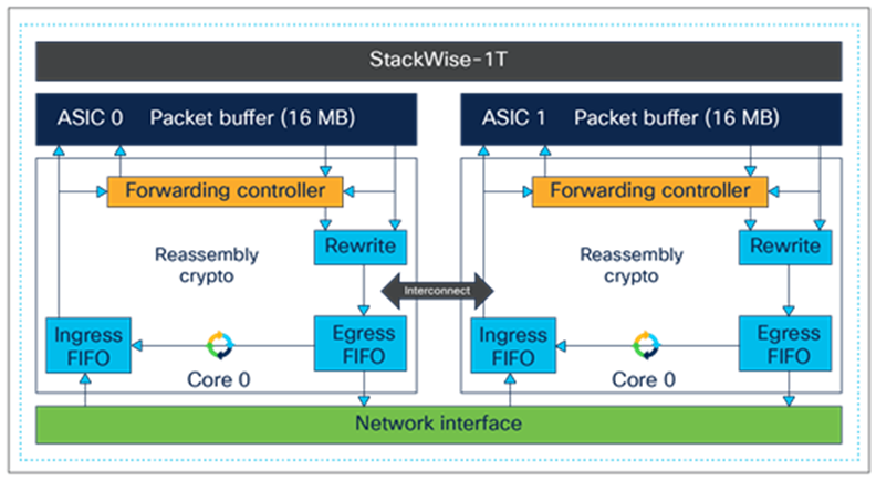
ASIC interconnect or internal stack interface
The Cisco Catalyst 9300 Series Switches come with either a single ASIC or dual ASICs, as explained later. The single-ASIC models do not use the stack interface but instead use a dedicated internal link for transporting traffic between ports belonging to separate cores. Communication between the front-panel ports on the same core are locally switched and do not use the internal link or stack interface. The models with dual ASICs leverage the internal stack interface for transporting traffic between the front-panel ports of different ASICs.
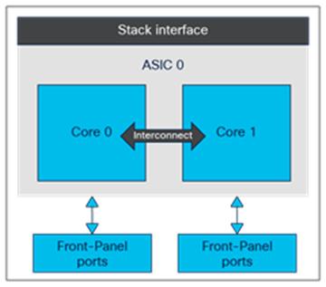
Single-ASIC diagram
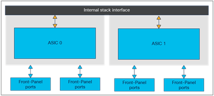
Dual-ASIC diagram
The stack interface is capable of switching 240 Gbps between the UADP 2.0 ASICs and 540 Gbps between the UADP 2.0sec ASICs. Internally this stack interface consists of six rings, each capable of 40/90 Gbps, providing a cumulative bandwidth of 240 Gbps respectively (120Gbps full-duplex) on UADP 2.0/2.0XL and 540 Gbps (full-duplex) respectively (dedicated to switching traffic between the ASICs.
Stack interface features include:
● No packet size limitations
● Packet type agnostic
● Packet data is spread across all the rings
● Header compression capabilities
● No buffering on stack interface
StackWise-1T/480/320 Architecture
The Cisco Catalyst 9300 Series provides the ability to combine multiple switches into one logical switch when connected together using special cables on StackWise-1T/480G/320G ports on the back. Up to eight switches can be connected in the stack, delivering operational simplicity and higher port density with combined switching capacity and maximum resiliency.
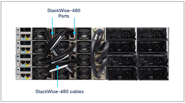
Switches stacked using StackWise cables which are common between C9300 and C9300X models
Stacking in the Cisco Catalyst 9300 Series is enabled using a stack-ring fabric known as StackWise-1T/480/320. The “1T” or “480” or “320” in the name refers to the total available stack capacity: 1 Tbps or 480 Gbps or 320 Gbps. The fabric consists of six counter-rotating rings (40 Gbps per ring) for modular uplink C9300 models, six counter-rotating rings (90 Gbps per ring) for modular uplink C9300X models, and four counter-rotating rings (40 Gbps per ring) for fixed uplink C9300L models, and the system’s throughput is a function of the aggregated throughput of these rings (540/ 240/160 Gbps). A technique called spatial reuse doubles throughput on the stack’s rings. Spatial reuse is enabled by destination-based packet stripping and also by allowing multiple flows to coexist. Spatial reuse frees available bandwidth on the ring, as the destination switch strips packets destined to itself, allowing other stack members to insert additional packets onto the ring.

StackWise-1T/480 architecture
Stackwise-1T/480/320 creates a unified control and management plane by electing one switch in the stack as an active switch and another switch as a hot standby. The remaining switches become stack members. The active switch is responsible for all Layer 2 and Layer 3 network control processing and for synchronizing all state information with the hot standby. The active switch unifies management for the entire stack, performing configuration and monitoring for the stack.
The forwarding architecture is designed to provide distributed switching across all member switches in the stack. Each switch in the stack optimizes data plane performance by using its local hardware resources.
StackWise-1T/480/320 highlights
● Catalyst 9300X Modular uplink models when stacked with other C9300X models can leverage 1T StackWise Bandwidth
● Catalyst 9300 Modular uplink models when stacked with other modular uplink models including C9300X models will leverage common 480G StackWise Bandwidth
● Catalyst 9300B Higher scale models can only be stacked among C9300B higher scale models only.
● Catalyst 9300L/9300LM Fixed uplink models can only be stacked among fixed uplink models
● Stateful switchover/nonstop forwarding (SSO/NSF) support for all major protocols
● No packet size limitations
● Packet type agnostic
● No buffering on stack interface
● Packet data is spread across all the rings
Note: Data Stack Cables are common among all Modular Uplink Models including C9300X models.
Cisco StackPower aggregates all of the available power within a switch stack into one common pool and shares power among all stack members. In the event of power supply failure, excess power can be redistributed very quickly. Up to four switches can be configured in a power stack. It requires the use of Cisco StackPower cables connected to special ports on the back of each switch. StackWise-1T/480 must first be enabled before StackPower may be used. Thus, if there is an eight-member data stack, two power stacks of four switches each can be configured to use the complete eight-member stack.
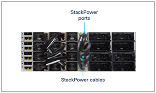
Power supplies aggregated with StackPower
Cisco StackPower has two modes of operation: shared and redundant.
In shared mode, the default, all input power is available for use anywhere in the stack. The total available power is used for power budgeting decisions. If a power supply fails, the remaining power available from the budget is used and there is no impact on either the system components or the PoE devices.
In redundant mode, power from the largest power supply is subtracted from the power budget. This reduces the total available power, but it allows backup power to be available in the event of a power supply failure.
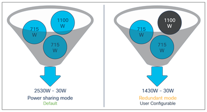
Comparing shared mode with redundant mode
Cisco StackPower also allows the deployment of larger power pools by using a Cisco Expandable Power System (XPS) 2200. This system shares power with up to eight switches. Catalyst 9300L Fixed uplink models do not support Stackpower.
Ethernet PHY (physical layer) connects a link layer device (often a MAC) to a physical medium such as a transceiver. PHY on the Cisco Catalyst 9300 Series Switches is a fully integrated Ethernet transceiver supporting steering and mapping of lanes back to the ASIC to support multiple speeds (1G, 10G, 25G, 40G and 100G), depending on the optics inserted on the front-panel ports.
Highlights of the C9300-24T, -24P, -24U, - 24UB, 24H, 24S, 9300L-24T-4G, 24P-4G, 24T-4, 24P-4X are as follows:
● 24x 1G RJ-45 Ethernet ports divided between the cores on a single ASIC
● 24x 1G SFP ports divided between the cores on a single ASIC for 9300-24S SKU
● 24P models offer PoE+ on all ports
● 24U models offer PoE+ or UPOE on all ports
● 24H models offer PoE+, or UPOE or UPOE+ on all ports
● Out of two 40G uplink ports, one connects to ASIC0/Core0 and the other connects to ASIC0/Core1
● 1G/10G uplink ports are equally distributed across Core 0 and Core 1
● Port mapping:
◦ Ports 1 through 16 are mapped to ASIC0/Core1, and Ports 17 through 24 are mapped to ASIC0/Core0
● Advanced forwarding ASIC supports 40-Gbps single-flow traffic processing on uplink ports
C9300-24 port high-level block diagram
Highlights of the C9300-48T, -48P, and 48U, 48UB, 48H, 48S are as follows:
● 48x 1G RJ-45 Ethernet ports divided equally between the cores on a single ASIC
● 48x 1G SFP ports divided between the cores on a single ASIC for 9300-48S SKU
● 48P models offer PoE+ on all ports
● 48U models offer PoE+ or UPOE on all ports
● 48H models offer PoE+ or UPOE or UPOE+ on all ports
● Out of two 40G uplink ports, one connects to ASIC0/Core0 and the other connects to ASIC0/Core1
● Port mapping:
◦ Ports 1 through 24 are mapped to ASIC0/Core1, and ports 25 through 48 are mapped to ASIC0/Core0
● Advanced forwarding ASIC supports 40-Gbps single-flow traffic processing on uplink ports
Highlights of the C9300-24UX/24UXB are as follows:
● This model provides 24x 100M, 1G, 2.5G, 5G, or 10G RJ-45 Ethernet ports (for 10G, use Category 6a or 7 cables)
● All the ports are divided equally between the cores and ASICs
● This model also offers PoE+ or Cisco UPOE inline power on all ports
● Out of two 40G uplink ports, one connects to ASIC0/Core0 and the other connects to ASIC1/Core0
● Uplink ports adjust speeds based on the inserted uplink module. 10G ports become active with a 10G uplink module, and 40G ports become active with a 40G uplink module
● Port mapping:
◦ Ports 1 through 6 are mapped to ASIC1/Core1, and ports 7 through 12 are mapped to ASIC1/Core0
◦ Ports 13 through 18 are mapped to ASIC0/Core1, and ports 19 through 24 are mapped to ASIC0/Core0
● Advanced forwarding ASIC supports 40-Gbps single-flow traffic processing on uplink ports
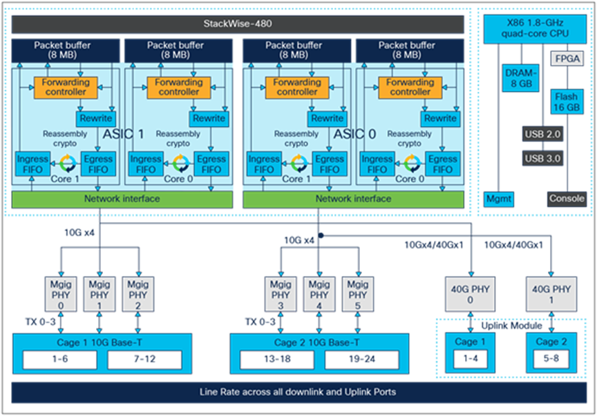
C9300-24UX high-level block diagram
Highlights of the C9300L-24UXG-4X, 24UXG-2Q are as follows:
● This model provides 16x 10M, 100M or 1G and 8x 100M, 1G, 2.5G, 5G, or 10G RJ-45 Ethernet ports (for 10G, use Category 6a or 7 cables)
● This model also offers PoE+ or Cisco UPOE inline power on all ports
● Out of two 40G uplink ports, one connects to ASIC0 and the other connects to ASIC1
● 10G uplinks are distributed equally between ASIC0 and ASCI1
● Port mapping:
◦ Ports 1 through 6 are mapped to ASIC1/Core1, and ports 7 through 12 are mapped to ASIC1/Core0
◦ Ports 13 through 18 are mapped to ASIC0/Core1, and ports 19 through 24 are mapped to ASIC0/Core0
● Advanced forwarding ASIC supports 40-Gbps single-flow traffic processing on uplink ports
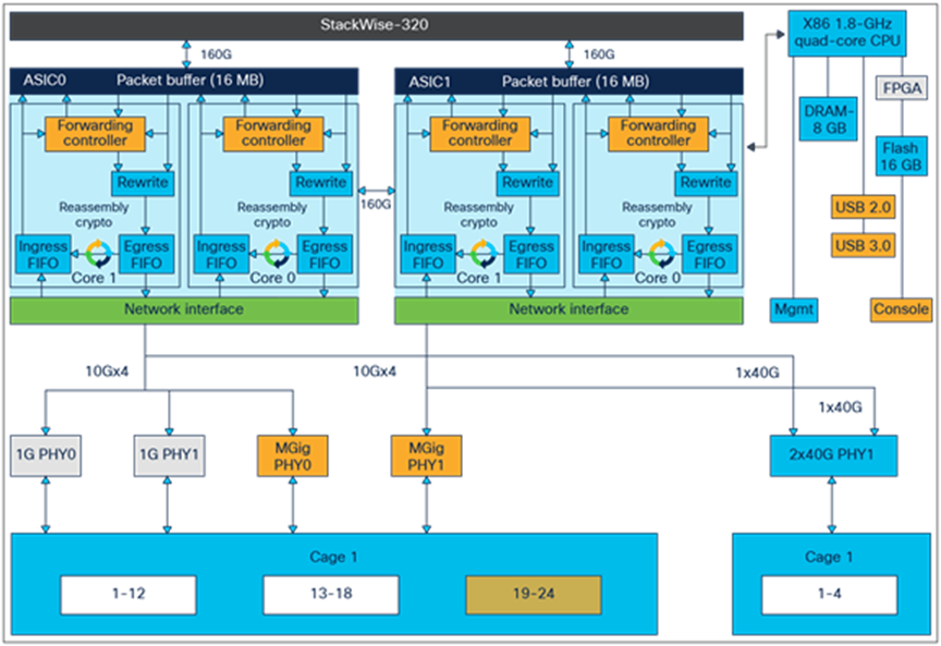
C9300L-24UXG-2Q high-level block diagram
Highlights of the C9300L-48UXG-4X, 48UXG-2Q are as follows:
● This model provides 36x 10M, 100M or 1G and 12x 100M, 1G, 2.5G, 5G, or 10G RJ-45 Ethernet ports (for 10G, use Category 6a or 7 cables)
● This model also offers PoE+ or Cisco UPOE inline power on all ports
● Out of two 40G uplink ports, one connects to ASIC0 and the other connects to ASIC1
● 10G uplinks are distributed equally between ASIC 0 and ASIC 1
● Port mapping:
◦ Ports 1 through 36 are mapped to ASIC1/Core1, and ports 37 through 40 are mapped to ASIC1/Core0
◦ Ports 41 through 48 are mapped to ASIC0/Core1
◦ Advanced forwarding ASIC supports 40-Gbps single-flow traffic processing on uplink ports
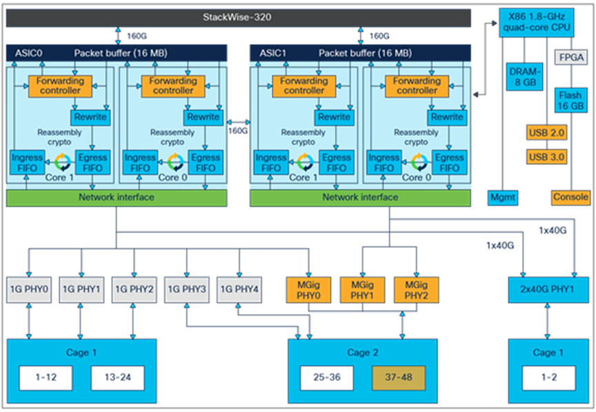
C9300L-24UXG-2Q high-level block diagram
Highlights of the C9300-48UXM are as follows:
● This model provides 36x 100M, 1G or 2.5G RJ-45 Ethernet ports and 12x 100M, 1G, 2.5G, 5G, or 10G RJ-45 Ethernet ports (for 10G, use Category 6a or 7 cables)
● This model also offers PoE+ and Cisco UPOE inline power on all ports
● Out of two 40G uplink ports, one connects to ASIC0/Core1 and the other connects to ASIC1/Core1
● Uplink ports adjust speeds based on the inserted uplink module. 10G ports become active with a 10G uplink module and 40G ports become active with a 40G uplink module
● Port mapping:
◦ Ports 1 through 18 (2.5G) and 37 through 42 (10G) are mapped to ASIC1
◦ Ports 19 through 36 (2.5G) and 43 through 48 (10G) are mapped to ASIC0
● Advanced forwarding ASIC supports 40-Gbps single-flow traffic processing on uplink ports
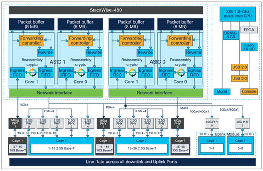
C9300-48UXM high-level block diagram
Highlights of the C9300-48UN are as follows:
● This model provides 48x 100M, 1G, 2.5, or 5G RJ-45 Ethernet ports
● This model also offers PoE+ and Cisco UPOE inline power on all ports
● Out of two 40G uplink ports, one connects to ASIC0/Core1 and the other connects to ASIC1/Core1
● Uplink ports adjust speeds based on the inserted uplink module. 10G ports become active with a 10G uplink module and 40G ports become active with a 40G uplink module
● Port mapping:
◦ Ports 1 through 18 (2.5G) and 37 through 42 (10G) are mapped to ASIC1
◦ Ports 19 through 36 (2.5G) and 43 through 48 (10G) are mapped to ASIC0
● Advanced forwarding ASIC supports 40-Gbps single-flow traffic processing on uplink ports
C9300-48UN high-level block diagram
Highlights of the C9300X- 48HX are as follows:
● This model provides 48x 100M, 1G, 2.5,5G and 10G RJ-45 Ethernet ports
● This model also offers UPoE+ inline power on all ports
● Out of four 100G uplink ports, two connects to ASIC0 and the other two connects to ASIC1
● Uplink ports adjust speeds based on the inserted uplink module. 10G ports become active with a 10G uplink module and 100/40G ports become active with a 100/40G uplink module
● Port mapping:
◦ Ports 1 through 24 (10G) are mapped to ASIC0
◦ Ports 25 through 48 (10G) are mapped to ASIC1
● Advanced forwarding ASIC supports 100/40-Gbps single-flow traffic processing on uplink ports
C9300X-48HX high-level block diagram
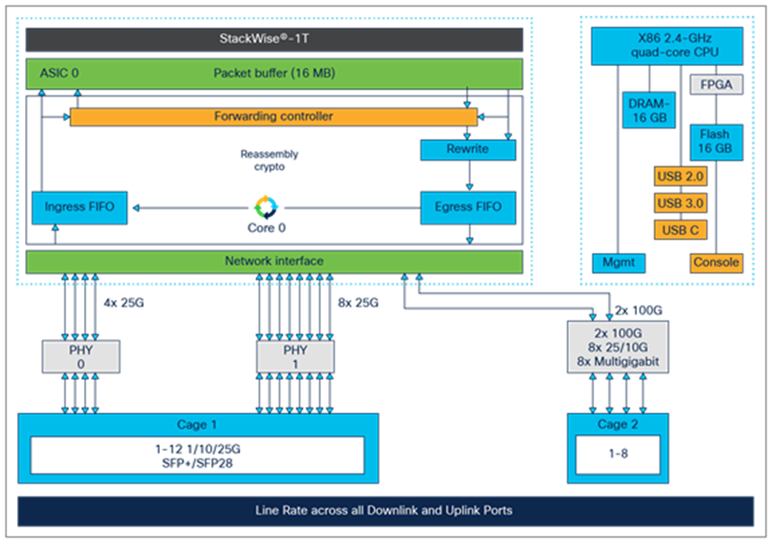
Highlights of the C9300X- 24HX and 48HXN are as follows:
● 9300X-24HX provides 24x 100M, 1G, 2.5,5G and 10G RJ-45 Ethernet ports
● C9300X-48HXN provides 40x 100M,1G,2.5G,5G and 8x100M,1G,2.5G,5G and 10G RJ-45 Ethernet ports
● C9300X-24HX and C9300X-48HXN models also offer UPoE+ inline power on all ports
● C9300X-24HX and C9300X-48HXN models only support single ASIC with maximum uplink capacity of 2x 100G
● Uplink ports adjust speeds based on the inserted uplink module. 10G ports become active with a 10G uplink module and 100/40G ports become active with a 100/40G uplink module
● Port mapping:
◦ All ports on both models are mapped to Single ASIC/Core
● Advanced forwarding ASIC supports 100/40-Gbps single-flow traffic processing on uplink ports
C9300X-24HX and C9300X-48HXN high-level block diagram
Highlights of the C9300X- 24Y and 12Y are as follows:
● 9300X-24Y provides 24x 1G, 10G and 25G SFP+/SFP28 Fiber ports
● C9300X-12Y provides 12x 1G, 10G and 25G SFP/SFP28 Fiber ports
● C9300X-24Y comprises of dual asics with support of 4x 100G Uplink Capacity
● C9300X-12Y comprises of single asics with support of 2x 100G Uplink Capacity
● Uplink ports adjust speeds based on the inserted uplink module. 10G ports become active with a 10G uplink module and 100/40G ports become active with a 100/40G uplink module
● Port mapping:
◦ All ports on 9300X-24Y are mapped across dual ASIC’s
◦ All ports on 9300X-12Y are mapped to Single ASIC/Core
● Advanced forwarding ASIC supports 100/40-Gbps single-flow traffic processing on uplink portsds
C9300X-24Y and C9300X-12Y high-level block diagram
Highlights of the C9300LM-48UX-4Y are as follows:
● This model provides 40x 10M, 100M or 1G and 8x 100M, 1G, 2.5G, 5G, or 10G RJ-45 Ethernet ports (for 10G, use Category 6a or 7 cables)
● This model also offers Cisco UPOE inline power on all ports
● All uplinks are distributed equally between ASIC 0.
● Port mapping:
◦ Ports 1 through 48 are mapped to ASIC0/Core0.
● Advanced forwarding ASIC supports 25-Gbps single-flow traffic processing on uplink ports
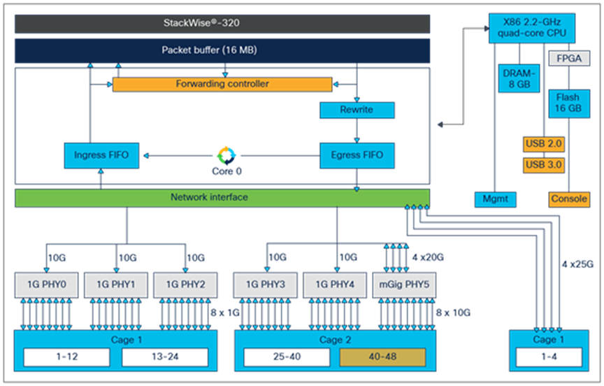
C9300LM-48UX-4Y high-level block diagram
C9300 and C9300X Network modules
The Cisco Catalyst 9300 Series supports five optional uplink network modules on all C9300 non-X models and four optional uplink network modules exclusively for all C9300X models as shown below. The default switch configuration does not include the network modules. All ports on the network module are line rate, and all software features supported on the switch downlink ports are also supported on the network module ports.
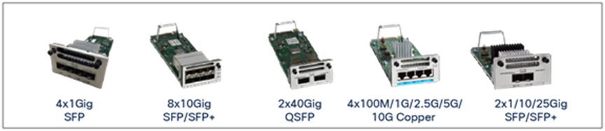
C9300 Network modules
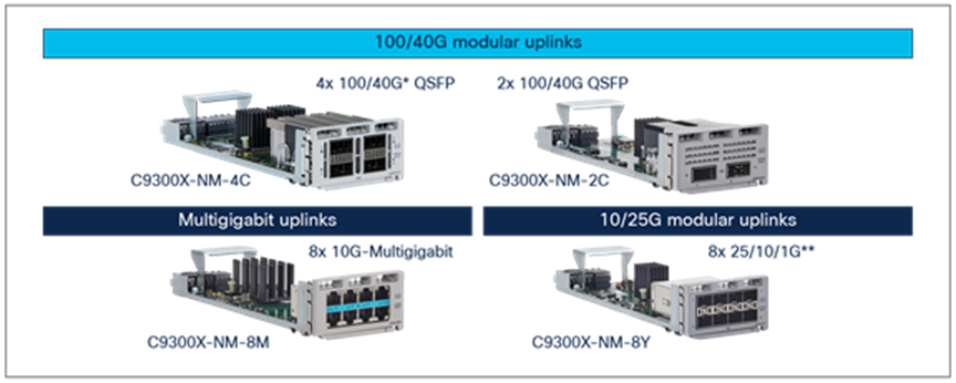
C9300X Network Modules
Highlights of the network modules are as follows:
● Uplink modules as shown above are exclusive for C9300 and C9300X only and cannot be mixed among each other
● Modules are automatically powered upon insertion
● Modules are OIR capable
● Modules are ACT2 authenticated
● Line rate on every port, with 10G, 25G, 40G and 100G single-flow traffic processing
● Speed is auto-negotiated depending on the optics inserted
Applications are used in enterprise networks for a variety of business-relevant use cases. Examples of enterprise applications include administrative tools such as performance monitors and protocol analyzers and security toolsets such as intrusion detection services, which traditionally operate on an external physical or virtual server.
This section specifies the SSD modules supported on Cisco Catalyst 9300 Series Switches. Their primary function is hosting third-party applications, and they also serve as general-purpose storage for packet captures, operating system trace logs, and Graceful Insertion and Removal (GIR) snapshots.
Cisco Catalyst 9300 Series Switches use the Cisco application framework known as Cisco IOx (the application framework combines Cisco IOS and Linux) to support applications containerized in KVM-based virtual machines, LXC (Linux Containers), or Docker containers.
Cisco IOS XE running on the Cisco Catalyst 9300 Series Switches reserves dedicated memory and CPU resources for application hosting. By reserving memory and CPU resources, the switch provides a separate execution space for user applications. This protects the switch’s Cisco IOS XE run-time processes, ensuring both its integrity and its performance.
Table 3. Application hosting resources
| Platform |
Memory |
CPU |
USB 3.0 |
| 9300/9300X (All Models) |
8/16 GB |
1.8/2.4 GHz |
120/240 GB |
Cisco Catalyst 9300 Series switches(except C9300LM) support for a field-replaceable USB 3.0 SSD on the rear of the chassis providing an extra 120/240 GB storage for application hosting only starting with Cisco IOS XE 16.9.1. The USB 3.0 SSD is enabled with S.M.A.R.T (Self-Monitoring, Analysis, and Reporting Technology) to monitor the reliability of the drive, predict drive failures, and carry out different types of drive self-tests. The USB 3.0 SSD module has one 120/240-GB partition, and Cisco IOS XE Software creates a partition with EXT4 as the default file system.
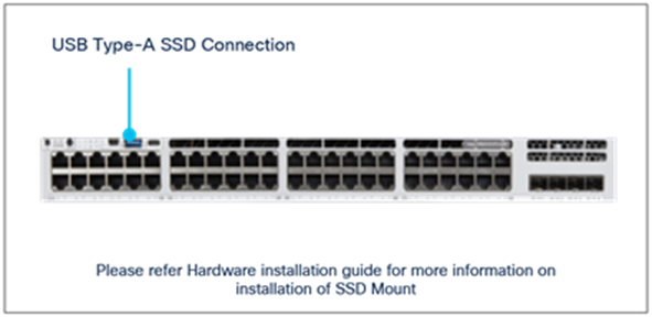
The Catalyst 9300LM Series come up with a mount kit to install SSD on USB TYPE-A port on the Front Panel.
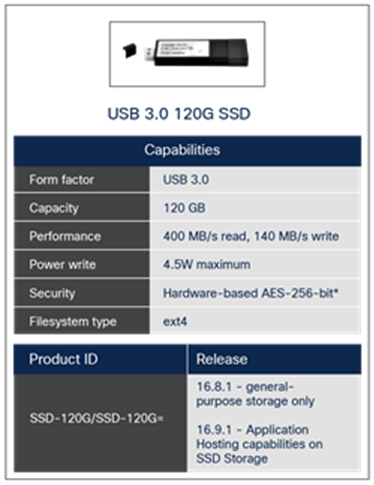
120-GB SSD specifications
This section provides a high-level overview of how packet forwarding is performed on the Cisco Catalyst 9300 Series Switches. Since the UADP ASICs used on all C9300 SKUs are architecturally equivalent, single unicast packet walks are described.
Ingress and egress unicast forwarding within ASIC
The figure below illustrates unicast packet forwarding within the ASIC.
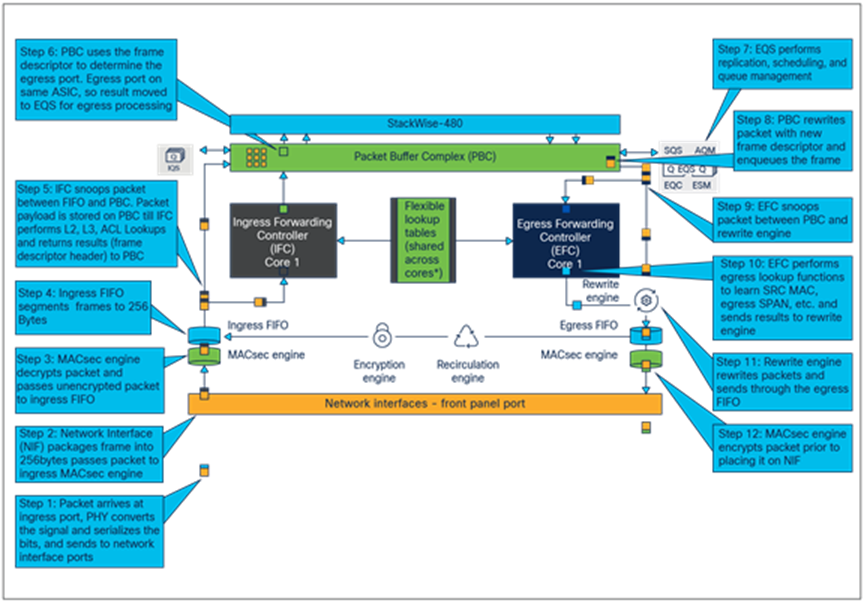
Packet walk within ASIC
The following is the basic sequence of events when packets enter the Cisco Catalyst 9300 Series front-panel ports:
1. Packet arrives at ingress port. PHY converts the signal and serializes the bits, and then sends the packet to the NIF (network interface) on the ASIC.
2. NIF packages frame into 256-byte chunks and moves them to the ingress MACsec engine. NIF also implements 1588 timestamping and EEE if enabled.
3. MACsec engine is a cut-through, fixed-latency cryptography engine to support 802.1AE MAC Security. Core cryptography of Layer 2 Cisco TrustSec® and output frames go to ingress FIFO.
4. Ingress FIFO collects the frames in 256-byte segments and transmits them to the unified Packet Buffer Complex (PBC).
5. Ingress Forwarding Controller (IFC) snoops packets between ingress FIFO and PBC and performs frame processing and a series of table lookups to deliver the resulting frame descriptor to PBC.
6. PBC is the primary packet store on the UADP ASIC. It uses the 64-byte frame descriptor to determine the egress port and QoS treatment of the frame. As the egress port is on the same ASIC, PBC performs local switching by allowing frames to be enqueued directly into egress queues.
7. EQS (Egress queues and scheduler) is responsible for queue management, replication, and scheduling packets. EQS enqueues packets arriving from the local ingress path into egress queue structures and then schedules them for transmission to the corresponding egress ports.
8. PBC receives the packet handle/results from the EQS block and sends the packet to egress FIFO through the rewrite engine.
9. EFC (egress forwarding controller) snoops the frames as it moves from PBC to the rewrite engine.
10. EFC completes egress lookup functions (such as egress SPAN and recirculation) and generate the rewrite descriptor to the rewrite engine.
11. RWE (rewrite engine) performs packet rewrite with new descriptor. Packets are rewritten first and then fragmented if necessary and sent to the egress port FIFO. The egress port FIFO provides storage for frames awaiting transmission to either NIF or to the recirculation path.
12. Egress MACsec performs fixed-latency and wire-rate encryption required by the frame for 802.1AE or Layer 2 Cisco TrustSec and then passes the frame on to the NIF in a cut-through manner.
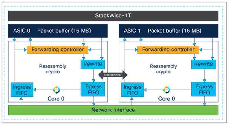
Ingress and egress unicast forwarding across ASICs
The figure below illustrates unicast packet forwarding across ASICs.
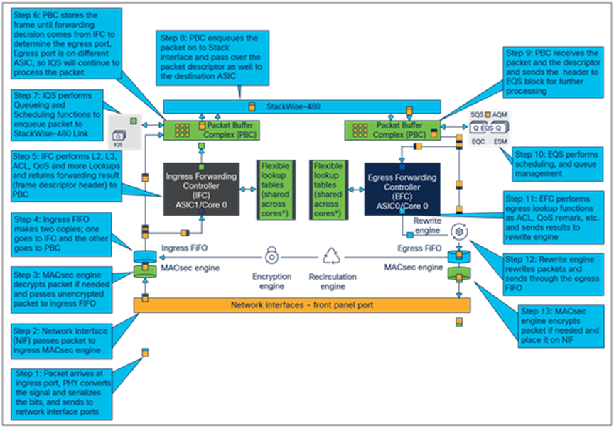
Packet walk across ASICs
The following is the basic sequence of events when packets enter the Cisco Catalyst 9300 Series front-panel ports:
1. Packet arrives at ingress port. PHY converts the signal and serializes the bits, and then sends the packet to the NIF (network interface) on the ASIC.
2. NIF packages frame into 256-byte chunks and moves them to the ingress MACsec engine. NIF also implements 1588 timestamping and EEE if enabled.
3. MACsec engine is a cut-through, fixed-latency cryptography engine to support 802.1AE MAC Security. Core cryptography of Layer 2 Cisco TrustSec and output frames go to ingress FIFO.
4. Ingress FIFO collects the frames in 256-byte segments and transmits them to the unified Packet Buffer Complex (PBC).
5. Ingress Forwarding Controller (IFC) snoops packets between Ingress FIFO and PBC and performs frame processing and a series of table lookups to deliver the resulting frame descriptor to PBC.
6. PBC is the primary packet store on the UADP ASIC. It uses the 64-byte frame descriptor to determine the egress port and QoS treatment of the frame. As the egress port is on a remote UADP ASIC, PBC sends the frame descriptor to the Ingress Queue and Scheduler (IQS).
7. IQS provides queueing and scheduling functions along with congestion management (priority packets are enqueued first on the stack interface) before sending packet to remote UADP ASICs.
8. IQS notifies PBC to dequeue a frame from the stack interface once the queues are available for transmission.
9. Packets arriving from the stack interface are buffered in PBC and a descriptor is sent to EQS for further processing.
10. EQS (Egress Queues and Scheduler) is responsible for queue management, replication, and scheduling packets. EQS enqueues packets arriving from the local ingress path into egress queue structures and then schedules them for transmission to the corresponding egress ports.
11. PBC receives the packet handle/results from the EQS bock and sends the packet to egress FIFO through the rewrite engine.
12. EFC (Egress Forwarding Controller) snoops the frames as it moves from PBC to the rewrite engine.
13. EFC completes egress lookup functions (such as egress SPAN and recirculation) and writes the rewrite descriptor to the rewrite engine.
14. RWE (rewrite engine) performs packet rewrite with new descriptor and fragmentation. Packets are rewritten first and then fragmented if necessary and sent to the egress port FIFO. The egress port FIFO provides storage for frames awaiting transmission to either NIF or the recirculation path.
15. Egress MACsec perform fixed-latency and wire-rate encryption required by the frame for 802.1AE or Layer 2 Cisco TrustSec and then passes the frame on to the NIF in a cut-through manner.
Cisco Catalyst 9300 Series Switches are the enterprise-class access switches in the Cisco Catalyst 9000 family, offering a comprehensive portfolio and architectural flexibility with 1/2.5/5 and 10-Gbps downlink ports and 10-, 25-, 40- and 100-Gbps uplink ports. This new platform is based on Cisco’s next-generation programmable UADP ASIC for increased bandwidth, scale, security, and telemetry. The platform also supports infrastructure investment protection with nondisruptive migration from 10G to 25G and beyond. The Cisco Catalyst 9300 Series is built on a flexible stacking architecture designed to provide high performance to meet the evolving needs of highly scalable and growing enterprise networks.
Additional websites that offer more details about the Cisco Catalyst 9300 Series and its capabilities:
Cisco Catalyst 9300 Series Switches Data Sheet
Cisco Catalyst 9300 Series Switches Hardware Installation Guides