Deploy Cisco UCS C125 M5 Servers with 2nd Gen AMD EPYC CPUs with VMware vSphere 7.0 and Horizon 7.12
Available Languages
Bias-Free Language
The documentation set for this product strives to use bias-free language. For the purposes of this documentation set, bias-free is defined as language that does not imply discrimination based on age, disability, gender, racial identity, ethnic identity, sexual orientation, socioeconomic status, and intersectionality. Exceptions may be present in the documentation due to language that is hardcoded in the user interfaces of the product software, language used based on RFP documentation, or language that is used by a referenced third-party product. Learn more about how Cisco is using Inclusive Language.
Organizations increasingly are adopting hybrid-cloud strategies, and Cisco® architecture, in particular, the Cisco Unified Computing System™ (Cisco UCS®), is at the center of on-premises infrastructure. This document describes an architecture using Cisco UCS Manager Release 4.1(2), Cisco UCS C125 M5 Rack Server Nodes with Second-Generation (2nd Gen) AMD EPYC processors, VMware vSphere Release 7.0, VMware Horizon Release 7.12, and a “white box” (or generic) storage array. Cisco UCS Manager 4.1(2) provides consolidated support for all current Cisco UCS fabric interconnect models (Cisco UCS 6200, 6300, and 6400 Series Fabric Interconnects; Cisco UCS 6324 Fabric Interconnect; and Cisco UCS Mini), Cisco UCS 2200, 2300, and 2400 Series Fabric Extenders, Cisco UCS B-Series Blade Servers, and Cisco UCS C-Series Rack Servers. This design also includes the Cisco Intersight™ management platform.
This section describes the Cisco components used in the architecture.
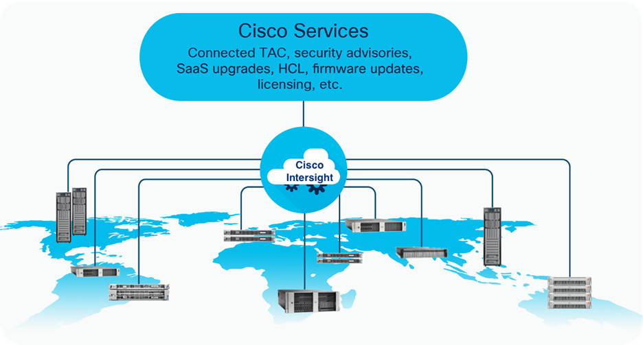
The Cisco Intersight platform is a software-as-a-service (SaaS) infrastructure lifecycle management platform that delivers simplified configuration, deployment, maintenance, and support. With the Cisco Intersight platform, customers get all the benefits of SaaS delivery and the full lifecycle management of Cisco Intersight connected distributed servers and third-party storage systems across data centers, remote sites, branch offices, and edge environments (Figure 1).
The Cisco Intersight platform is designed to be modular, so customers can adopt services based on their individual requirements. The platform significantly simplifies IT operations by bridging applications with infrastructure, providing visibility and management from bare-metal servers and hypervisors to serverless applications, thereby reducing costs and mitigating risk. This unified SaaS platform uses a unified OpenAPI that natively integrates with the third-party platforms and tools.
Cisco Intersight overview
The main benefits of Cisco Intersight infrastructure services are summarized here:
● Simplify daily operations by automating many daily manual tasks.
● Combine the convenience of a SaaS platform with the capability to connect from anywhere and manage infrastructure through a browser or mobile app.
● Stay ahead of problems and accelerate trouble resolution through advanced support capabilities.
● Gain global visibility into infrastructure health and status along with advanced management and support capabilities.
● Upgrade to add workload optimization and Kubernetes services when needed.
Cisco Unified Computing System components
The main components of Cisco UCS are listed here:
● Computing: The system is based on an entirely new class of computing system that incorporates blade servers based on Intel® Xeon® Scalable family processors.
● Network: The system is integrated on a low-latency, lossless, 25 Gigabit Ethernet unified network fabric. This network foundation consolidates LANs, SANs, and high-performance computing (HPC) networks, which are separate networks today. The unified fabric lowers costs by reducing the number of network adapters, switches, and cables needed, and by decreasing the power and cooling requirements.
● Virtualization: The system unleashes the full potential of virtualization by enhancing the scalability, performance, and operational control of virtual environments. Cisco security, policy enforcement, and diagnostic features now extend into virtualized environments to better support changing business and IT requirements.
● Storage access: The system provides consolidated access to local storage, SAN storage, and network-attached storage (NAS) over the unified fabric. With storage access unified, Cisco UCS can access storage over Ethernet, Fibre Channel, Fibre Channel over Ethernet (FCoE), and Small Computer System Interface over IP (iSCSI) protocols. This capability provides customers with choices for storage access and investment protection. In addition, server administrators can pre-assign storage-access policies for system connectivity to storage resources, simplifying storage connectivity and management and helping increase productivity.
● Management: Cisco UCS uniquely integrates all system components, enabling the entire solution to be managed as a single entity by Cisco UCS Manager. Cisco UCS Manager has an intuitive GUI, a CLI, and a robust API for managing all system configuration processes and operations.
Figure 2 provides an overview of a Cisco UCS deployment.
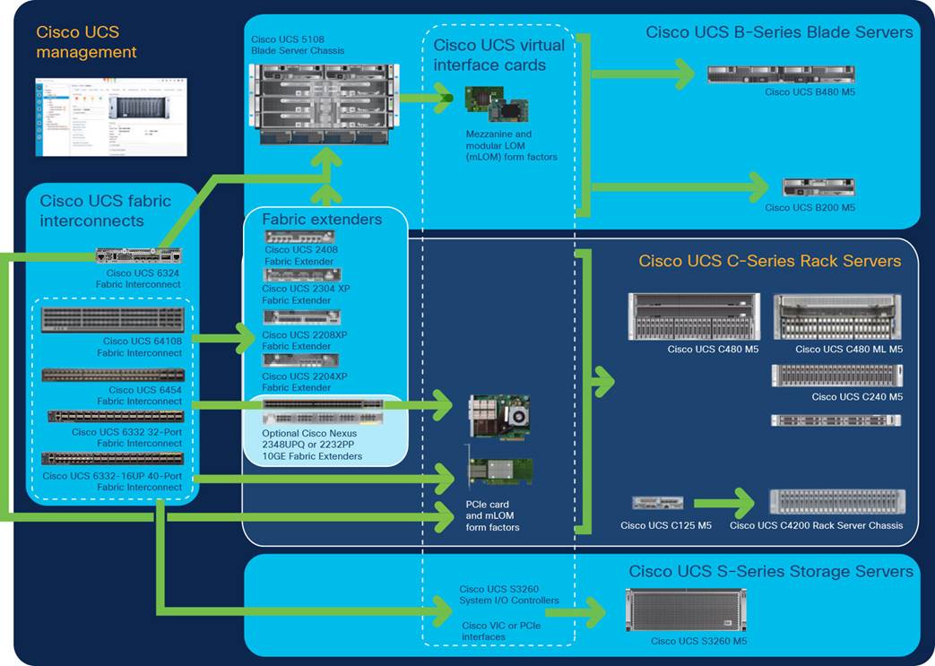
Cisco Data Center Overview
Cisco UCS is designed to deliver these benefits:
● Reduced TCO and increased business agility
● Increased IT staff productivity through just-in-time provisioning and mobility support
● A cohesive, integrated system that unifies the technology in the data center; the system is managed, serviced, and tested as a whole
● Scalability through a design for hundreds of discrete servers and thousands of virtual machines and the capability to scale I/O bandwidth to match demand
● Industry standards supported by a partner ecosystem of industry leaders
Cisco UCS Manager provides unified, embedded management of all software and hardware components of the Cisco UCS deployment across multiple chassis, rack servers, and thousands of virtual machines. Cisco UCS Manager manages Cisco UCS as a single entity through an intuitive GUI, a CLI, or an XML API for comprehensive access to all Cisco UCS Manager functions.
Cisco UCS 6400 Series Fabric Interconnects
Cisco UCS 6400 Series Fabric Interconnects (Figure 3 and Figure 4) are a core part of Cisco UCS, providing both network connectivity and management capabilities for the system. The Cisco UCS 6400 Series offers line-rate, low-latency, lossless 10/25/40/100 Gigabit Ethernet, FCoE, and Fibre Channel functions.
The Cisco UCS 6400 Series provides the management and communication backbone for Cisco UCS B-Series Blade Servers, 5108 Blade Server Chassis, C-Series Rack Servers managed by Cisco UCS, and S-Series Storage Servers. All servers attached to a Cisco UCS 6400 Series Fabric Interconnect become part of a single, highly available management domain. In addition, by supporting a unified fabric, Cisco UCS 6400 Series Fabric Interconnects provide both LAN and SAN connectivity for all servers in the domain.
From a networking perspective, the Cisco UCS 6400 Series uses a cut-through architecture, supporting deterministic, low-latency, line-rate 10/25/40/100 Gigabit Ethernet ports, switching capacity of 3.82 Tbps for the Cisco UCS 6454 Fabric Interconnect, 7.42 Tbps for the 64108 Fabric Interconnect, and 200 Gigabit Ethernet bandwidth between the 6400 Series Fabric Interconnect and the Cisco UCS 2408 Fabric Extender for each Cisco UCS 5108 Blade Server Chassis, independent of packet size and enabled services. The product family supports Cisco low-latency, lossless 10/25/40/100 Gigabit Ethernet unified network fabric capabilities, which increase the reliability, efficiency, and scalability of Ethernet networks. The fabric interconnect supports multiple traffic classes over a lossless Ethernet fabric from the server through the fabric interconnect. Significant TCO savings come from an FCoE-optimized server design in which network interface cards (NICs), host bus adapters (HBAs), cables, and switches can be consolidated.
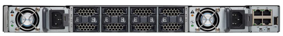
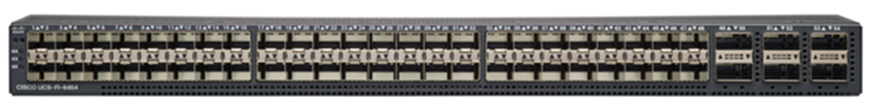
Cisco UCS 6400 Series Fabric Interconnects: Cisco UCS 6454 Fabric Interconnect front view
Cisco UCS 6400 Series Fabric Interconnects : Cisco UCS 6454 Fabric Interconnect rear view
Cisco UCS C4200 Series Rack Server Chassis with Cisco UCS C125 M5 Rack Server Node
The Cisco UCS C4200 Series Rack Server Chassis (Figure 5) is a modular, dense rack server chassis that supports up to four Cisco UCS C125 M5 Rack Server Nodes. This solution is optimized for use in environments requiring a dense computing form factor and high core densities such as scale-out computation-intensive, general service provider, and bare-metal applications.
The Cisco UCS C4200 chassis is a modular architecture consisting of the following modules:
● Base chassis: The chassis consists of 24 small-form-factor (SFF) drive bays segmented into four groups of six direct-attach drives (one group per node slot), four rear slots supporting C125 M5 server nodes, four redundant hot-pluggable fans, two 2400-watt (W) AC high-line redundant power supplies, and a rail mounting kit.
● Server node: Each C125 M5 has two sockets supporting the AMD EPYC 7001 (Naples) and AMD EPYC 2 7002 (Rome) processors at up to 180W thermal design power (TDP), 16 DIMM slots for 2666-MHz DDR4 DIMMs (Naples) or 3200-MHz DDR4 DIMMs (Rome), and capacity points up to 64 GB, up to two half-height and half-length PCI Express (PCIe) 3.0 slots, and an optional M.2 or Secure Digital (SD) module. The C125 supports SAS RAID through a PCIe 12-Gbps SAS storage controller card, disk arrays through a PCIe 12-Gbps SAS HBA, or SATA direct from the AMD EPYC CPU.
The node also includes a dedicated internal LAN mezzanine slot based on the Open Compute Project (OCP) 2.0 standard supporting networking speeds up to 100 Gbps. Additionally, a fourth-generation Cisco PCIe virtual interface card (VIC) can be added in the x16 PCIe 3.0 slot. An NVIDIA T4 graphics processing unit (GPU) is also supported.
The Cisco UCS C4200 can be used alone or as part of the Cisco Unified Computing System, which unifies computing, networking, management, virtualization, and storage access into a single integrated architecture, enabling end-to-end server visibility, management, and control in both bare-metal and virtualized environments.
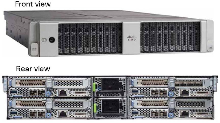
Cisco UCS C4200 Rack Server Chassis
Cisco UCS VIC 1455 converged network adapter
The Cisco UCS VIC 1455 (Figure 6) is a quad-port Small Form-Factor Pluggable (SFP28) half-height PCIe card designed for the M5 generation of Cisco UCS C-Series Rack Servers. The card supports 10/25 Gigabit Ethernet or FCoE. The card can present PCIe standards-compliant interfaces to the host, and these can be dynamically configured as either NICs or HBAs (Figure 7).
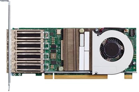
Cisco UCS VIC 1455
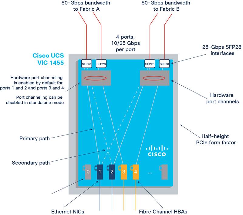
Cisco UCS VIC 1455 configuration
Cisco Nexus 93180YC-FX Switches
The Cisco Nexus® 93180YC-EX Switch (Figure 8) provides a flexible line-rate Layer 2 and Layer 3 feature set in a compact form factor. Designed with Cisco Cloud Scale technology, it supports highly scalable cloud architectures. With the option to operate in Cisco NX-OS or Cisco Application Centric Infrastructure (Cisco ACI™) mode, it can be deployed across enterprise, service provider, and Web 2.0 data centers.
The Cisco Nexus 93180YC-EX Switch offers these benefits:
● Architectural flexibility
◦ The switch provides top-of-rack or middle-of-row fiber-based server access connectivity for traditional and leaf-and-spine architectures.
◦ Leaf-node support for Cisco ACI architecture is on the roadmap.
◦ Gain increased scale and simplified management through support for Cisco Nexus 2000 Series Fabric Extenders.
● Comprehensive feature set
◦ Enhanced Cisco NX-OS Software is designed for performance, resiliency, scalability, manageability, and programmability.
◦ Infrastructure is ready for Cisco ACI support, helping users take advantage of automated policy-based systems management.
◦ Virtual Extensible LAN (VXLAN) routing provides network services.
◦ Line-rate data collection provides comprehensive traffic flow telemetry information.
◦ Monitor traffic microbursts and application traffic patterns using real-time buffer utilization information per port and per queue.
● Highly available and efficient design
◦ The switch uses a high-density, nonblocking architecture.
◦ The switch is easily deployed in either a hot-aisle and cold-aisle configuration.
◦ The switch uses redundant, hot-swappable power supplies and fan trays.
● Simplified operations
◦ Power-on autoprovisioning (POAP) support allows simplified software upgrades and configuration file installation.
◦ An intelligent API offers switch management through remote procedure calls (RPCs), JavaScript Object Notation (JSON), or XML over an HTTP/HTTPS infrastructure.
◦ Python scripting provides programmatic access to the switch CLI.
◦ The switch supports hot and cold patching and online diagnostics.
● Investment protection
A Cisco 40 Gigabit Ethernet bidirectional transceiver allows reuse of an existing 10 Gigabit Ethernet multimode cabling plant for 40 Gigabit Ethernet support for 1/10 Gigabit Ethernet access connectivity for data centers migrating access switching infrastructure to faster speeds. The following are supported:
● 1.8 Tbps of bandwidth in a 1-rack-unit (1RU) form factor
● 48 fixed 1/10/25 Gigabit Ethernet enhanced SFP+ ports
● 6 fixed 40/100 Gigabit Ethernet QSFP+ for uplink connectivity
● Latency of less than 2 microseconds
● Front-to-back or back-to-front airflow configurations
● 1+1 redundant hot-swappable 80 Plus Platinum-certified power supplies
● Hot-swappable 3+1 redundant fan trays
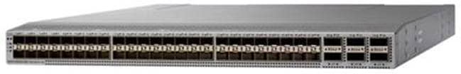
Cisco Nexus 93180YC-EX Switch
Cisco MDS 9132T 32-Gbps 32-Port Fibre Channel Switch
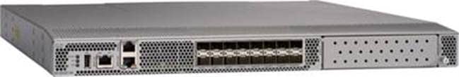
The next-generation Cisco MDS 9132T 32-Gbps 32-Port Fibre Channel Switch (Figure 9) provides high-speed Fibre Channel connectivity from the server rack to the SAN core. It empowers small, midsize, and large enterprises that are rapidly deploying cloud-scale applications using extremely dense virtualized servers, providing the dual benefits of greater bandwidth and consolidation.
Small-scale SAN architectures can be built from the foundation using this low-cost, low-power, nonblocking, line-rate, low-latency fixed standalone SAN switch, capable of bidirectional airflow, connecting both storage and host ports.
Medium-size to large-scale SAN architectures built with SAN core directors can expand 32-Gbps connectivity to the server rack using these switches either in switch mode or Network Port Virtualization (NPV) mode.
Additionally, investing in this switch for a lower-speed (4-, 8-, or 16-Gbps) server rack gives you the option to upgrade to 32-Gbps server connectivity in the future using the 32-Gbps HBAs that are available today. The Cisco MDS 9132T switch also provides exceptional flexibility through a unique port expansion module (Figure 10) that provides a robust cost-effective, field-swappable port upgrade option.
This switch also offers state-of-the-art SAN analytics and telemetry capabilities, which are built in to this next-generation hardware platform. This new state-of-the-art technology couples the next-generation port application-specific integrated circuit (ASIC) with a fully dedicated network processing unit designed to complete analytics calculations in real time. The telemetry data extracted from the inspection of the frame headers is analyzed within the switch and, using an industry-leading open format, can be streamed to any analytics-visualization platform. This switch also includes a dedicated 10/100/1000BASE-T telemetry port to accelerate data delivery to any telemetry receiver, including Cisco Data Center Network Manager.
Cisco 9132T 32-Gbps 32-Port Fibre Channel Switch
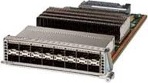
Cisco MDS 9132T 32-Gbps 16-Port Fibre Channel Port Expansion Module
The Cisco MDS 9132T offers these main features:
● High performance: The Cisco MDS 9132T architecture, with chip-integrated nonblocking arbitration, provides consistent 32-Gbps low-latency performance across all traffic conditions for every Fibre Channel port on the switch.
● Capital expenditures (CapEx) savings: The 32-Gbps ports allow users to deploy them on existing 16- or 8-Gbps transceivers, reducing initial CapEx with an option to upgrade to 32-Gbps transceivers and adapters in the future.
● High availability: Cisco MDS 9132T switches continue to provide the same outstanding availability and reliability as the previous generation of Cisco MDS 9000 Family switches by providing optional redundancy on all major components such as the power supply and fan. Dual power supplies also facilitate redundant power grids.
● Pay-as-you-grow design: The Cisco MDS 9132T Fibre Channel switch provides an option to deploy as few as eight 32-Gbps Fibre Channel ports in the entry-level variant, which can grow by 8 ports to 16 ports, and thereafter, with a port expansion module with sixteen 32-Gbps ports, to up to 32 ports. This approach results in lower initial investment and power consumption for entry-level configurations of up to 16 ports compared to a fully loaded switch. Upgrading through an expansion module also reduces the overhead needed to manage multiple instances of port activation licenses on the switch. This unique combination of port upgrade options allow four possible configurations of 8 ports, 16 ports, 24 ports, and 32 ports.
● Next-generation ASIC: The Cisco MDS 9132T Fibre Channel switch is powered by the same high-performance 32-Gbps Cisco ASIC with an integrated network processor that powers the Cisco MDS 9700 48-Port 32-Gbps Fibre Channel Switching Module. Among all the advanced features that this ASIC enables, one of the most notable is inspection of Fibre Channel and Small Computer System Interface (SCSI) headers at wire speed on every flow in the smallest form-factor Fibre Channel switch without the need for any external taps or appliances. The recorded flows can be analyzed on the switch and also exported using a dedicated 10/100/1000BASE-T port for telemetry and analytics purposes.
● Intelligent network services: Slow-drain detection and isolation, VSAN technology, access control lists (ACLs) for hardware-based intelligent frame processing, smart zoning, and fabric-wide quality of service (QoS) enable migration from SAN islands to enterprisewide storage networks. Traffic encryption is optionally available to meet stringent security requirements.
● Sophisticated diagnostics: The Cisco MDS 9132T provides intelligent diagnostics tools such as Inter-Switch Link (ISL) diagnostics, read diagnostic parameters, protocol decoding, network analysis tools, and integrated Cisco Call Home capability for greater reliability, faster problem resolution, and reduced service costs.
● Virtual machine awareness: The Cisco MDS 9132T provides visibility into all virtual machines logged into the fabric. This feature is available through HBAs that can priority tag the virtual machine identifier (VMID) on every Fibre Channel frame. Virtual machine awareness can be extended to intelligent fabric services such as analytics to visualize the performance of every flow originating from each virtual machine in the fabric.
● Programmable fabric: The Cisco MDS 9132T provides powerful representational state transfer (REST) and Cisco NX-API capabilities to enable flexible and rapid programming of utilities for the SAN as well as polling point-in-time telemetry data from any external tool.
● Single-pane management: The Cisco MDS 9132T can be provisioned, managed, monitored, and troubleshot using Cisco Data Center Network Manager, which currently manages the entire suite of Cisco data center products.
● Self-contained advanced anticounterfeiting technology: The Cisco MDS 9132T uses on-board hardware that protects the entire system from malicious attacks by securing access to critical components such as the bootloader, system image loader, and Joint Test Action Group (JTAG) interface.
This section provides an overview of the infrastructure setup, software and hardware requirements, and some of the design details for a deployment using Cisco UCS C125 M5 servers with 2nd Gen AMD EPYC CPUs for enterprise end users with VMware vSphere 7.0 and Horizon 7.12. This section does not cover the design details or configuration of components such as Cisco Nexus and Cisco MDS switches and storage array systems because their designs and configurations conform to various Cisco Validated Designs for converged infrastructure and are covered widely elsewhere. This document focuses on the design elements and performance of the AMD platform for virtual desktop infrastructure (VDI) deployments.
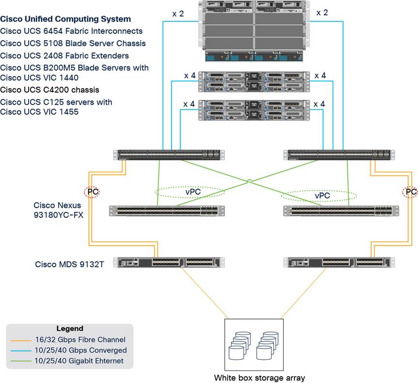
Physical architecture
The components deployed include the following:
● Two Cisco Nexus 93180YC-FX Switches
● Two Cisco MDS 9132T 32-Gbps Fibre Channel switches
● Two Cisco UCS 6454 Fabric Interconnects
● One Cisco UCS 5108 Blade Server Chassis
● Two Cisco UCS C4200 Series Rack Server Chassis
● Two Cisco UCS B200 M5 Blade Servers with Intel Xeon Silver 4210 CPUs and 392 GB of 3200-MHz memory (hosting infrastructure virtual machines)
● Eight Cisco UCS C125 Rack Server Nodes with AMD EPYC 7552 and 2 TB of 3200-MHz memory (hosting virtual desktops)
● White-box storage array
The logical architecture is based on Cisco Validated Designs and supports up to 2870 users in two Cisco UCS C4200 chassis containing eight Cisco UCS C125 servers, with physical redundancy for the blade servers for each workload type. This design is illustrated in Figure 12. For desktop virtualization, the deployment includes VMware Horizon 7.12 running on VMware vSphere ESXi 7.0 GA.
This design is intended to provide a large-scale building block for VMware Horizon desktops on Cisco UCS C125 servers.
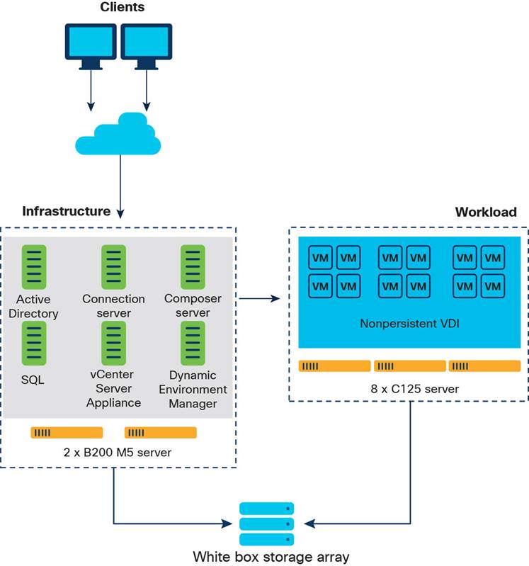
Logical architecture
Table 1 lists the software and hardware versions used in the solution described in this document.
Table 1. Software and firmware versions
| Component |
Version |
| Cisco UCS component firmware |
Release 4.1(2b) bundle |
| Cisco UCS Manager |
Release 4.1(2b) bundle |
| Cisco UCS B200 M5 blades |
Release 4.1(2b) bundle |
| Cisco VIC 1440 |
Release 4.1(2b) bundle |
| Cisco UCS C125 server |
Release 4.1(2b) bundle |
| Cisco VIC 1455 |
Release 4.1(2b) bundle |
| VMware vCenter Server Appliance |
Release 7.0.0.10400 |
| VMware vSphere 7. 0 GA |
Release 7.0.0.15843807 |
| VMware Horizon Connection Server |
Release 7.12.0.15770369 |
| VMware Dynamic Environment Manager Enterprise |
Release 10.0.0.945 |
| VMware Horizon Agent |
Release 7.12 |
| VMware Tools |
Release 11.0.5.15389592 |
Creating Cisco UCS BIOS policy
To create a server BIOS policy for VMware ESXi hosts, follow these steps:
1. In Cisco UCS Manager, click Servers.
2. Expand Policies > root.
3. Right-click BIOS Policies.
4. Choose Create BIOS Policy.
5. Enter C125-Host as the BIOS policy name.
6. Click OK. Then click OK again to create the BIOS policy.
7. Expand BIOS Policies and choose the newly created BIOS policy. Set the following options on the Main tab of the policy:
◦ CDN Control: Enabled
◦ Quiet Boot: Disabled
8. Click the Advanced tab, leaving the Processor tab selected within the Advanced tab. Scroll down and set the following options on the Processor tab:
◦ Core Performance Boost: Auto
◦ Global C-state Control: Disabled
◦ L1 Stream HW Prefetcher: Enabled
◦ L2 Stream HW Prefetcher: Enabled
◦ Determinism Slider: Power
◦ IOMMU: Enabled
◦ AMD Memory Interleaving: Auto
◦ AMD Memory Interleaving Size: Auto
◦ SMEE: Enabled
◦ SMT Mode: Auto
◦ SVM Mode: Enabled
9. Click Save Changes.
10. Click OK.
Note: For more information, see Performance Tuning for Cisco UCS C125 Rack Server Nodes with AMD Processors.
Figure 13 shows the BIOS policy settings.
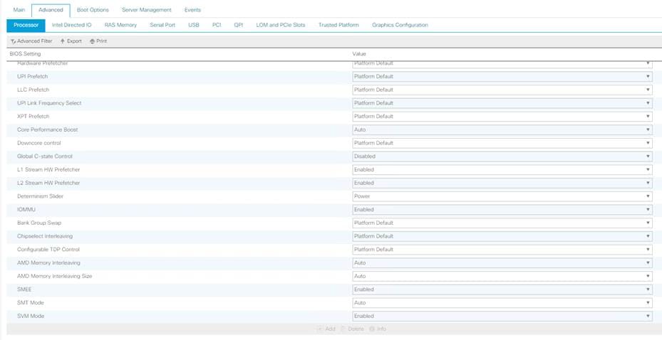
Cisco UCS C125 BIOS policy settings
Getting started with the Cisco Intersight platform
The Cisco Intersight platform provides an integrated and intuitive management experience for resources in the traditional data center and at the edge. With flexible deployment options to address complex security needs, getting started with the Cisco Intersight platform is quick and easy.
To configure the Cisco Intersight platform, follow these steps:
1. If you do not already have a Cisco Intersight account, to claim your Cisco UCS system in a new account on Cisco Intersight, connect to https://intersight.com. If you have an existing Cisco Intersight account, connect to https://intersight.com and sign in with your Cisco ID, select the appropriate account, and skip to step 6.
2. Click Create an account.
3. Sign in with your Cisco ID.
4. Read, scroll through, and accept the End User License Agreement and click Next.
5. Enter an account name and click Create.
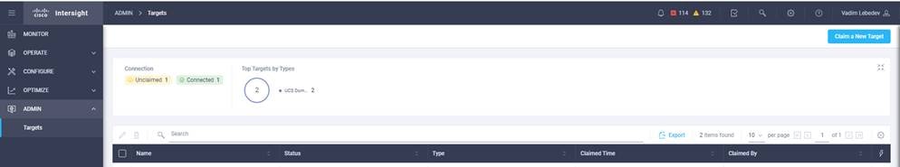
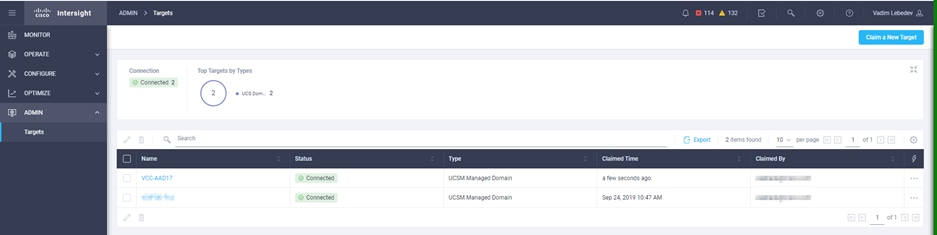
6. Choose ADMIN > Targets. Click Claim a New Target.
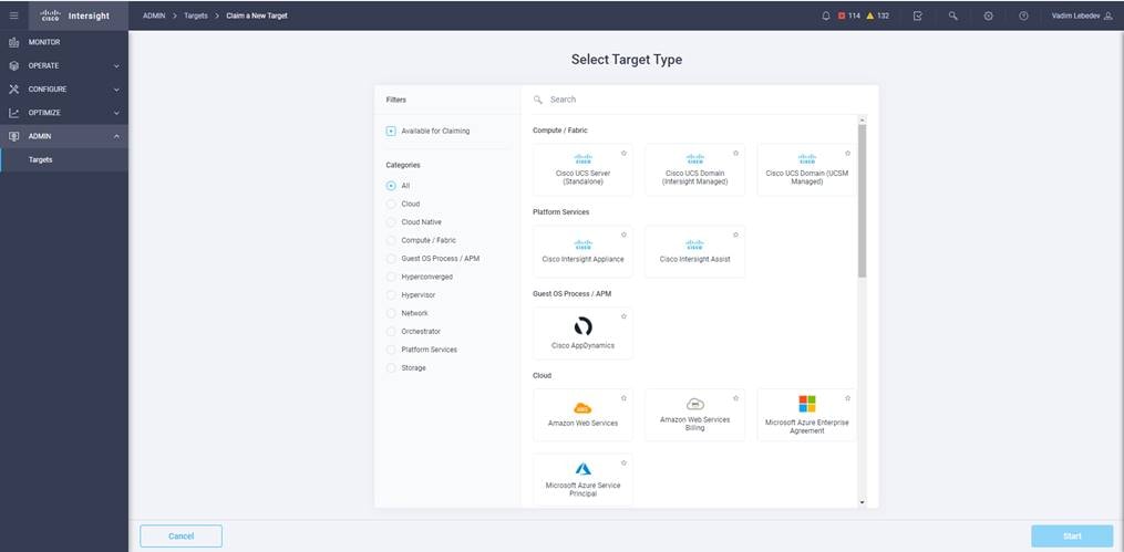
7. Select Cisco UCS Domain (UCSM Managed) and click Start.
8. Fill in the device ID and claim code and click Claim.
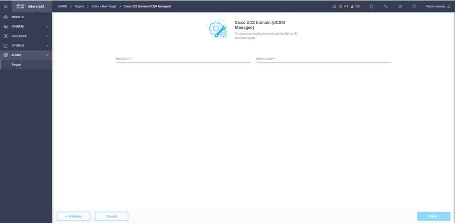
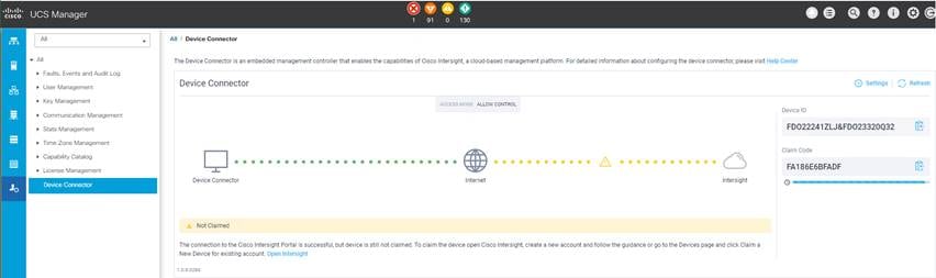
Note: The device ID and claim code can be obtained by connecting to Cisco UCS Manager and choosing Admin > All > Device Connector. The device ID and claim code are on the right.
9. The target will be visible in the list of your available targets.
10. From the Cisco Intersight window, click the gear icon (![]() )and then click Licensing. If this is a new account, all servers connected to the Cisco UCS domain will appear under the Base license tier. If you have purchased Cisco Intersight licenses and have them in your Cisco Smart Account, click Register and follow the prompts to register this Cisco Intersight account in your Cisco Smart Account. Cisco Intersight also offers a one-time 90-day trial of Premier licensing for new accounts. Click Start Trial and then Start to begin this evaluation. The remainder of this section assumes that you are using Premier licensing.
)and then click Licensing. If this is a new account, all servers connected to the Cisco UCS domain will appear under the Base license tier. If you have purchased Cisco Intersight licenses and have them in your Cisco Smart Account, click Register and follow the prompts to register this Cisco Intersight account in your Cisco Smart Account. Cisco Intersight also offers a one-time 90-day trial of Premier licensing for new accounts. Click Start Trial and then Start to begin this evaluation. The remainder of this section assumes that you are using Premier licensing.
Configure VMware Horizon to prepare the master target virtual machines and create a VDI instant clone desktop pool.
Prepare master target virtual machines
Virtual machines for the master targets must first be installed with the software components needed to build the golden images. Additionally, all available security patches for the Microsoft operating system and Microsoft Office should be installed.
Preparing the master virtual machines requires four major steps: install the operating system and VMware Tools, install the application software, install the VMware Horizon Agent, and optimize the image with the VMware OS Optimization Tool (OSOT).
Note: VMware OSOT, the optimization tool, includes customizable templates to enable or disable Microsoft Windows system services and features using VMware recommendations and best practices across multiple systems. Because most Windows system services are enabled by default, the optimization tool can be used to easily disable unnecessary services and features to improve the performance of your virtual desktops.
Note: The images contain the basic features needed to run the Login VSI workload.
The master target virtual machine was configured as outlined in Table 2.
Table 2. Configuration of VDI virtual machines
| Configuration |
VDI virtual machines |
| Operating system |
Microsoft Windows 10 64-bit |
| Virtual CPU amount |
2 |
| Memory amount |
4-GB reserve for all guest memory |
| Network |
VMXNET3 VDI |
| Virtual disk (vDisk) size |
32 GB |
| Additional software used for testing |
Microsoft Office 2019 Login VSI 4.1.25 (Knowledge Worker Workload) |
Create a VDI instant clone desktop pool
To create a VDI instant clone desktop pool, follow these steps:
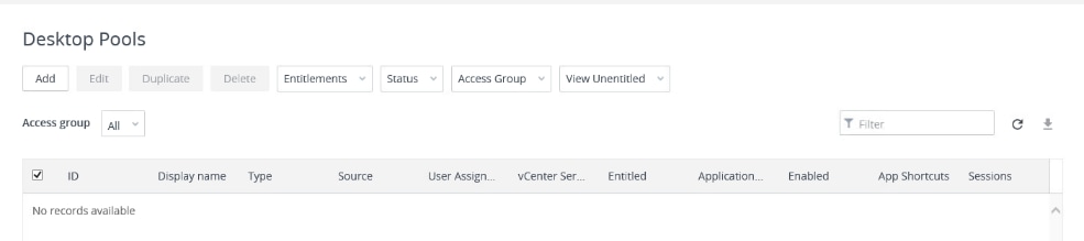
1. In the Horizon Console, in the left plane, expand Inventory and select Desktops. Click Add.
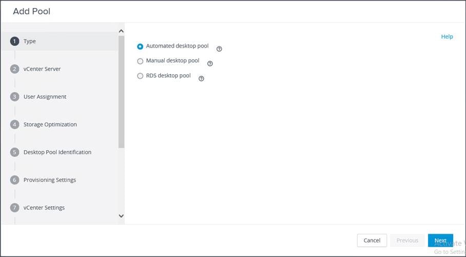
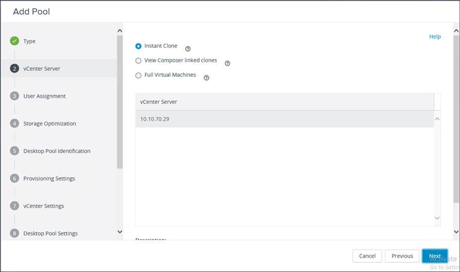
2. Select the type of desktop pool to be created. Click Next.
3. Choose the provisioning type for the desktops in the pool (Instant Clones and Full Virtual Machines pools were used in this design). Click Next.
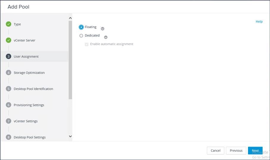
4. Select the user assignment to be used by the desktop pool. Click Next.
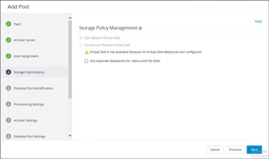
5. Select the required option for Storage Policy Management. Click Next.
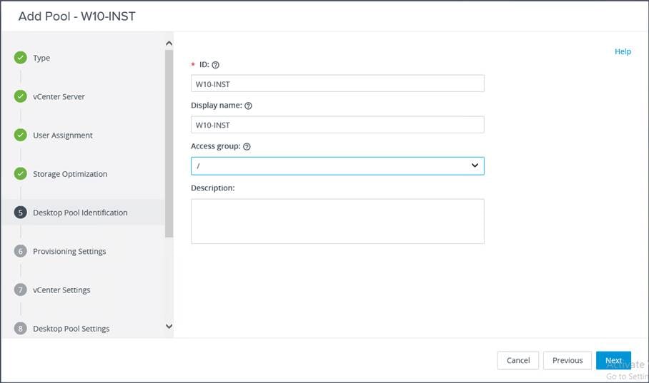
6. Provide the desktop pool ID and the virtual display name. Click Next.
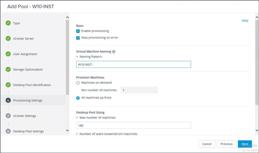
7. Provide the naming pattern and the number of desktops to be provisioned. Click Next.
This validated design used these settings:
● Single server pool: 410
● Cluster pool: 2870
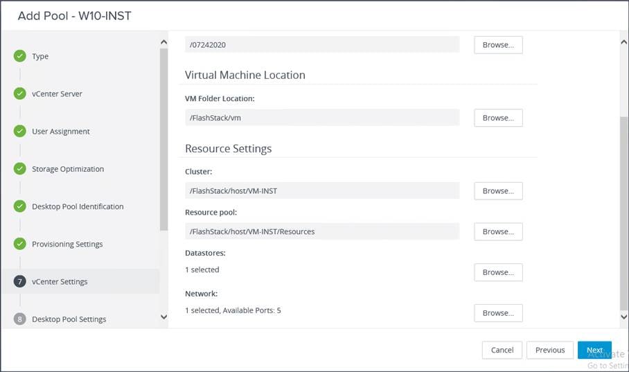
8. Provide the parent virtual machine, snapshot, host and cluster information, and data-store information for the virtual machines to create. Click Next.
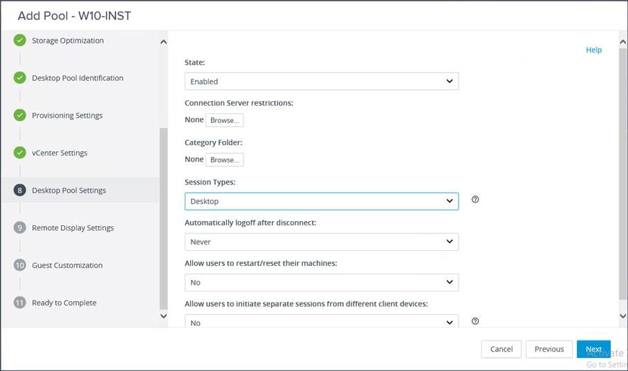
9. For Desktop Pool Settings, configure the state and the session type. Click Next.
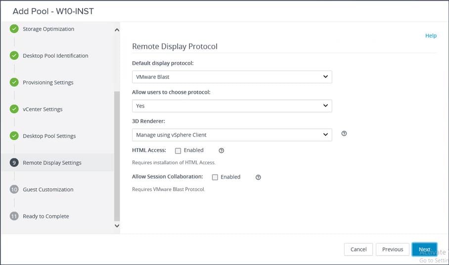
10. Configure the Remote Display Protocol settings. Click Next.
11. Select the Microsoft Active Directory container for desktops to place in a domain controller computer location.
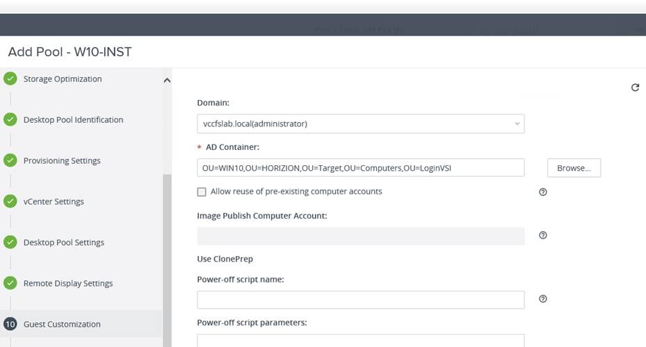
12. Review all the deployment specifications and click Finish to complete the deployment.
13. Select “Entitle users” after this wizard finishes to enable the desktop user group and users to access this pool.
The testing results focused on the entire process of the virtual desktop lifecycle by capturing metrics during desktop boot-up, user logon, virtual desktop acquisition (also referred to as ramp-up,) user workload processing (also referred to as steady-state), and user logoff for the VDI session under test.
Test metrics were gathered from the virtual desktop and load-generation software to assess the overall success of an individual test cycle.
A recommended maximum workload was determined by the Login VSI Knowledge Worker Workload in VSI Benchmark Mode end user experience measurements and server operating parameters.
This recommended maximum workload approach allows you to determine the server N+1 fault tolerance load the blade can successfully support in the event of a server outage for maintenance or upgrade.
Our recommendation is that the Login VSI Average Response and VSI Index Average should not exceed the Baseline plus 2000 milliseconds to ensure that end user experience is outstanding. Additionally, during steady state, the processor utilization should average no more than 90-95 percent.
You can obtain additional information and a free test license from http://www.loginvsi.com.
Note: Memory should never be oversubscribed for Desktop Virtualization workloads.
The recommended maximum workload for a Cisco UCS C125 server with dual AMD EPYC 7552 processors and 2 TB of 3200-MHz RAM is 410 Microsoft Windows 10 64-bit VDI nonpersistent virtual machines (instant clones) with two virtual CPUs (vCPUs) and 4 GB of RAM.
Login VSI data is shown in Figure 14.
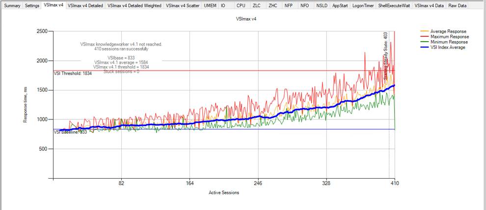
Single-server recommended maximum workload using VMware Horizon 7.12 VDI: VSI score
Performance data for the server running the workload is shown in Figure 15, Figure 16, and Figure 17.
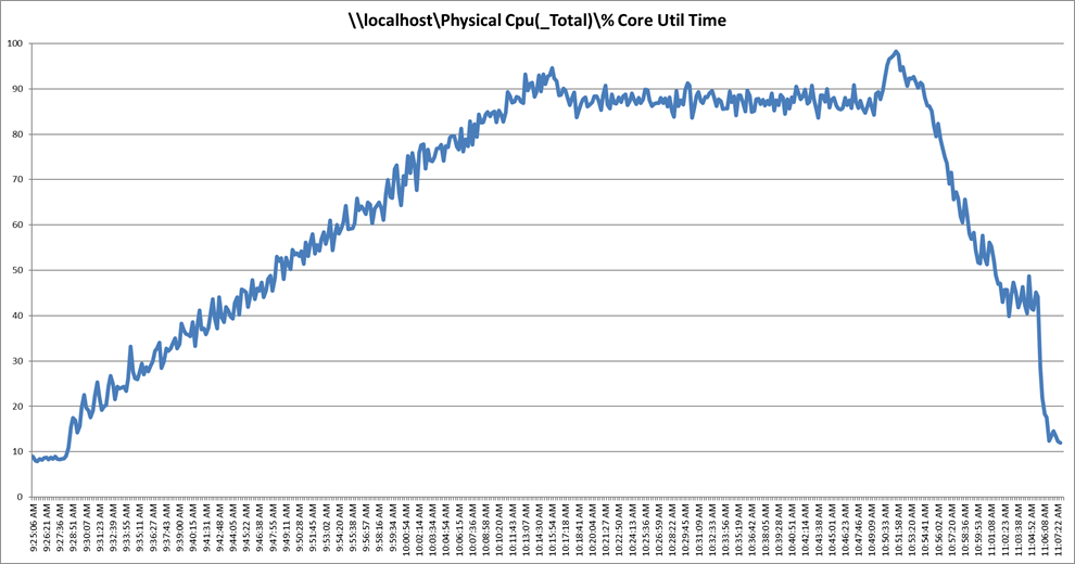
Single-server recommended maximum workload using VMware Horizon 7.12 VDI: Host CPU utilization
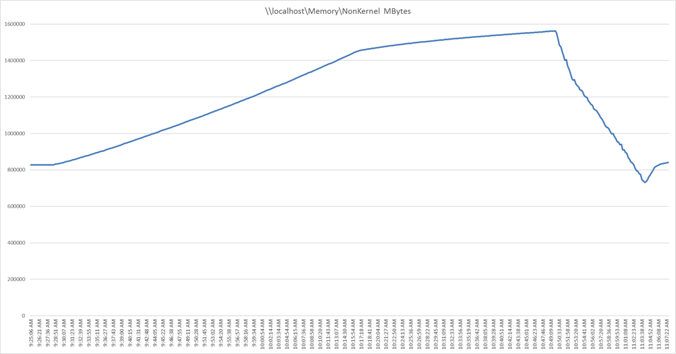
Single-server recommended maximum workload using VMware Horizon 7.12 VDI: Host memory utilization
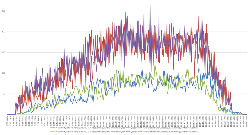
Single-server recommended maximum workload using VMware Horizon 7.12 VDI: Host network utilization
This section presents the key performance metrics that were captured on the Cisco UCS C125 servers with dual AMD EPYC 7552 processors and 2 TB of 3200-MHz RAM during cluster testing in the N+1 environment. The cluster testing used Microsoft Windows 10 64-bit VDI nonpersistent virtual machines (instant clones) with two vCPUs and 4 GB of RAM.
Login VSI data is shown in Figure 18.
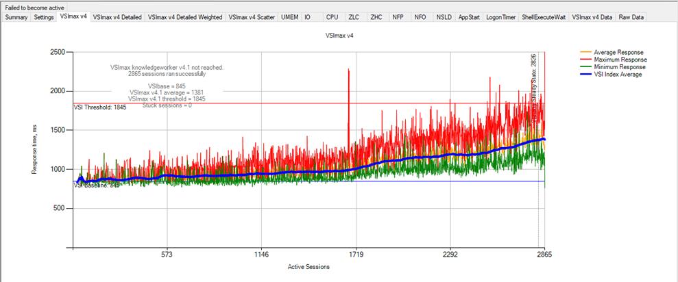
Scale testing using VMware Horizon 7.12 VDI: VSI score
Performance data for the server running the workload is shown in Figure 19, Figure 20, Figure 21, and Figure 22.
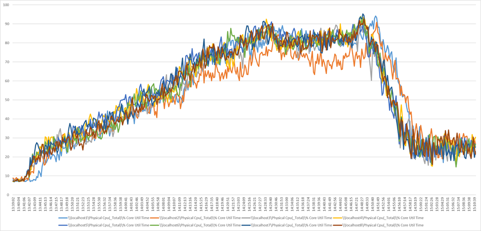
Scale workload using VMware Horizon 7.12 VDI: Host CPU utilization
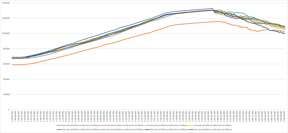
Scale workload using VMware Horizon 7.12 VDI: Host memory utilization
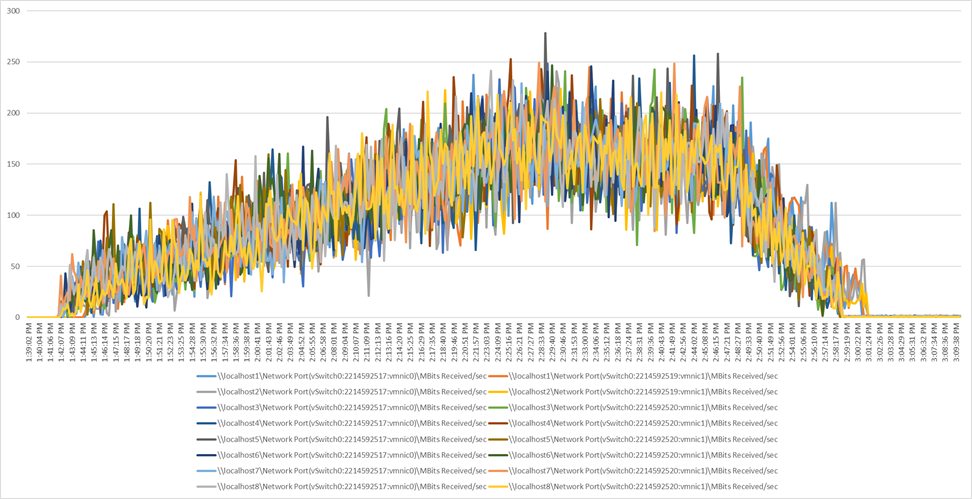
Scale workload using VMware Horizon 7.12 VDI: Host network utilization (received)
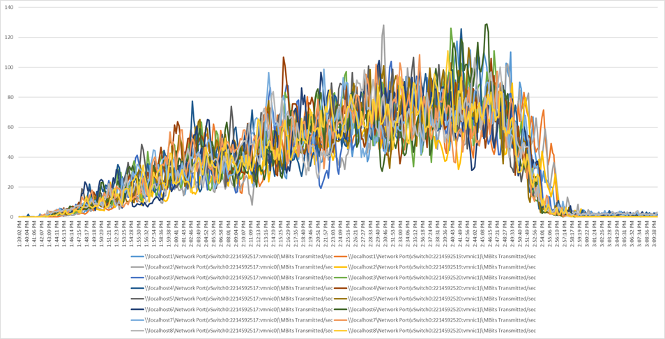
Scale workload using VMware Horizon 7.12 VDI: Host network utilization (transmitted)
Integrating the Cisco Intersight platform into your environment provides global visibility of infrastructure health and status along with a constantly growing list of advanced management and support capabilities.
Consult the following references for additional information about the topics discussed in this document.
Products and solutions
● Cisco Intersight
https://www.intersight.com
● Cisco Unified Computing System:
http://www.cisco.com/en/US/products/ps10265/index.html
● Cisco UCS 6454 Fabric Interconnect:
https://www.cisco.com/c/en/us/products/collateral/servers-unified-computing/datasheet-c78-741116.html
● Cisco UCS 5100 Series Blade Server Chassis:
http://www.cisco.com/en/US/products/ps10279/index.html
● Cisco UCS C4200 Series Rack Server Chassis:
https://www.cisco.com/c/en/us/products/servers-unified-computing/ucs-c4200-series-rack-server-chassis/index.html
● Cisco UCS B-Series Blade Servers:
https://www.cisco.com/c/en/us/products/servers-unified-computing/ucs-b-series-blade-servers/index.html
● Cisco UCS C-Series Rack Servers:
https://www.cisco.com/site/us/en/products/computing/servers-unified-computing-systems/ucs-c-series-rack-servers/index.html
● Cisco UCS adapters:
http://www.cisco.com/en/US/products/ps10277/prod_module_series_home.html
● Cisco Nexus 9000 Series Switches:
http://www.cisco.com/c/en/us/products/switches/nexus-9000-series-switches/index.html
● Cisco UCS Hardware Compatibility List (HCL):
https://ucshcltool.cloudapps.cisco.com/public/
● Design guide for FlexPod Datacenter with VMware vSphere 7.0 and Cisco UCS C125 M5 servers with 2nd Gen AMD EPYC CPUs: https://www.cisco.com/c/en/us/td/docs/unified_computing/ucs/UCS_CVDs/fp_vmware_vsphere_70_C125_m5.html