ASA/PIX: NTP mit und ohne IPsec-Tunnel - Konfigurationsbeispiel
Inhalt
Einleitung
Dieses Dokument enthält eine Beispielkonfiguration für die Synchronisierung der Uhr der PIX/ASA Security Appliance mit einem Netzwerkzeitserver über das Network Time Protocol (NTP). ASA1 kommuniziert direkt mit dem Netzwerkzeitserver. ASA2 leitet NTP-Datenverkehr durch einen IPSec-Tunnel an ASA1 weiter. ASA1 leitet die Pakete wiederum an den Netzwerkzeitserver weiter.
Weitere Informationen zur identischen Konfiguration auf der Cisco ASA mit Version 8.3 und höher finden Sie unter ASA 8.3 und höher: NTP mit und ohne IPsec-Tunnel-Konfigurationsbeispiel.
Hinweis: Ein Router kann auch als NTP-Server zur Synchronisierung der PIX/ASA Security Appliance-Uhr verwendet werden.
Voraussetzungen
Anforderungen
Stellen Sie sicher, dass die folgenden Anforderungen erfüllt sind, bevor Sie diese Konfiguration ausprobieren:
-
Vor Beginn dieser NTP-Konfiguration muss eine End-to-End-IPsec-Verbindung hergestellt werden.
-
Die Security Appliance-Lizenz muss für die DES-Verschlüsselung (Data Encryption Standard) aktiviert sein (mindestens Verschlüsselungsstufe).
Verwendete Komponenten
Die Informationen in diesem Dokument basieren auf folgenden Software- und Hardware-Versionen:
-
Cisco Adaptive Security Appliance (ASA) mit Version 7.x und höher
-
ASDM Version 5.x und höher
Hinweis: Weitere Informationen dazu, wie die ASA vom ASDM konfiguriert werden kann, finden Sie unter Zulassen des HTTPS-Zugriffs für ASDM.
Die Informationen in diesem Dokument beziehen sich auf Geräte in einer speziell eingerichteten Testumgebung. Alle Geräte, die in diesem Dokument benutzt wurden, begannen mit einer gelöschten (Nichterfüllungs) Konfiguration. Wenn Ihr Netz Live ist, überprüfen Sie, ob Sie die mögliche Auswirkung jedes möglichen Befehls verstehen.
Verwandte Produkte
Diese Konfiguration kann auch mit der Cisco Security Appliance der Serie PIX 500 verwendet werden, die Version 7.x oder höher ausführt.
Hinweis: NTP-Unterstützung wurde in PIX-Version 6.2 hinzugefügt. Weitere Informationen zur Konfiguration von NTP auf der Cisco PIX-Firewall finden Sie unter PIX 6.2: NTP mit und ohne IPsec-Tunnel-Konfigurationsbeispiel.
Konventionen
Weitere Informationen zu Dokumentkonventionen finden Sie unter Cisco Technical Tips Conventions (Technische Tipps von Cisco zu Konventionen).
Konfiguration
Netzwerkdiagramm
In diesem Dokument wird die in dieser Abbildung gezeigte Netzwerkeinrichtung verwendet.
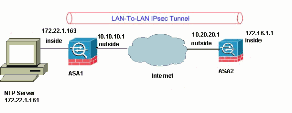
Hinweis: Die in dieser Konfiguration verwendeten IP-Adressierungsschemata sind im Internet nicht legal routbar. Es handelt sich um RFC 1918-Adressen, die in einer Laborumgebung verwendet wurden.
ASDM-Konfiguration des VPN-Tunnels
Gehen Sie wie folgt vor, um den VPN-Tunnel zu erstellen:
-
Öffnen Sie Ihren Browser, und geben Sie https://<Inside_IP_Address_of_ASA> ein, um auf das ASDM der ASA zuzugreifen.
Stellen Sie sicher, dass Sie alle Warnungen autorisieren, die Ihr Browser bezüglich der SSL-Zertifikatauthentizität ausgibt. Der Standardbenutzername und das Standardpasswort sind beide leer.
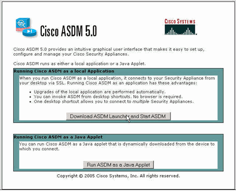
Die ASA zeigt dieses Fenster an, um den Download der ASDM-Anwendung zu ermöglichen. In diesem Beispiel wird die Anwendung auf den lokalen Computer geladen und nicht in einem Java-Applet ausgeführt.
-
Klicken Sie auf Download ASDM Launcher und Start ASDM, um das Installationsprogramm für die ASDM-Anwendung herunterzuladen.
-
Führen Sie nach dem Herunterladen des ASDM Launcher die Schritte aus, die durch die Eingabeaufforderungen geleitet werden, um die Software zu installieren und den Cisco ASDM Launcher auszuführen.
-
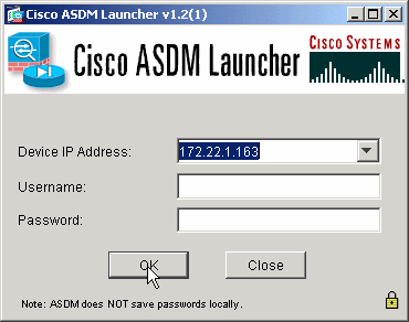
Geben Sie die IP-Adresse für die Schnittstelle ein, die Sie mit dem Befehl http - konfiguriert haben, sowie einen Benutzernamen und ein Kennwort, wenn Sie einen Benutzernamen und ein Kennwort angegeben haben.
In diesem Beispiel werden der Standardbenutzername und das Standardkennwort verwendet.
-
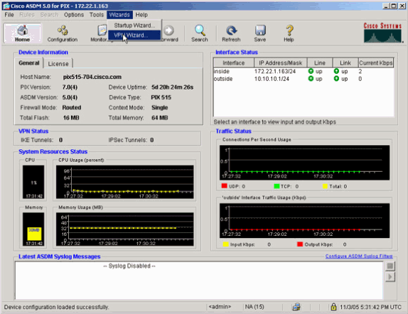
Führen Sie den VPN-Assistenten aus, sobald die ASDM-Anwendung eine Verbindung mit der ASA herstellt.
-
Wählen Sie den Typ des IPsec-VPN-Tunnels zwischen Standorten aus.
-
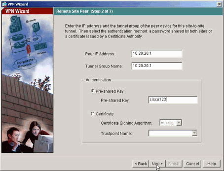
Geben Sie die externe IP-Adresse des Remote-Peers an. Geben Sie die zu verwendenden Authentifizierungsinformationen ein. Dies ist der vorinstallierte Schlüssel in diesem Beispiel.
-
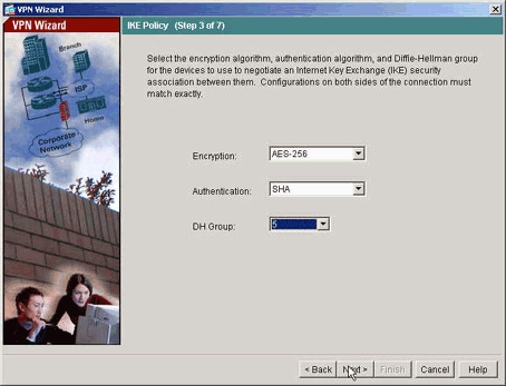
Geben Sie die Attribute für IKE an, die auch als Phase 1 bezeichnet werden. Diese Attribute müssen auf beiden Seiten des Tunnels gleich sein.
-
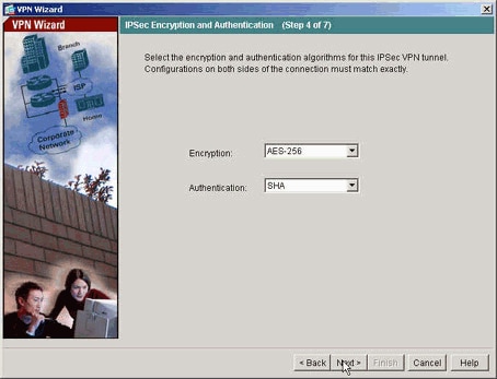
Geben Sie die Attribute an, die für IPsec verwendet werden sollen. Dies wird auch als Phase 2 bezeichnet. Diese Attribute müssen auf beiden Seiten übereinstimmen.
-
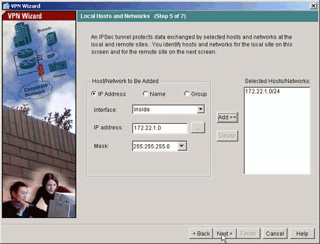
Geben Sie die Hosts an, deren Datenverkehr den VPN-Tunnel passieren darf. In diesem Schritt werden die lokalen Hosts von ASA1 angegeben.
-
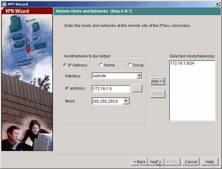
Die Hosts und Netzwerke auf der Remote-Seite des Tunnels werden angegeben.
-
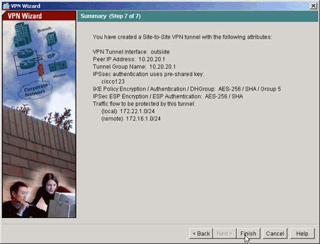
Die vom VPN Wizard definierten Attribute werden in dieser Übersicht angezeigt. Überprüfen Sie die Konfiguration erneut, und klicken Sie auf Fertig stellen, wenn Sie mit den richtigen Einstellungen zufrieden sind.
NTP-ASDM-Konfiguration
Gehen Sie wie folgt vor, um NTP auf der Cisco Security Appliance zu konfigurieren:
-
Wählen Sie auf der ASDM-Startseite Konfiguration aus, wie hier gezeigt:
-
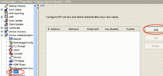
Wählen Sie nun Eigenschaften > Gerätemanagement > NTP aus, um die NTP-Konfigurationsseite von ASDM wie folgt zu öffnen:
-
Klicken Sie auf die Schaltfläche HINZUFÜGEN, um einen NTP-Server hinzuzufügen und die erforderlichen Attribute wie IP-Adresse, Schnittstellenname (innen oder außen), Schlüsselnummer und Schlüsselwert für die Authentifizierung in dem neuen Fenster anzugeben, das nach dem Klicken auf die Schaltfläche HINZUFÜGEN angezeigt wird, wie im Screenshot gezeigt. Klicken Sie dann auf OK.
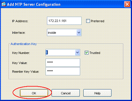
Hinweis: Der Schnittstellenname muss bei ASA1 "inside" und bei ASA2 "outside" heißen.
Hinweis: Der NTP-Authentifizierungsschlüssel sollte für ASA und NTP-Server identisch sein.
Die Konfiguration der Authentifizierungsattribute in der CLI für ASA1 und ASA2 wird im Folgenden dargestellt:
ASA1#ntp authentication-key 1 md5 cisco
ntp trusted-key 1
ntp server 172.22.1.161 key 1 source inside
ASA2#ntp authentication-key 1 md5 cisco
ntp trusted-key 1
ntp server 172.22.1.161 key 1 source outside
-
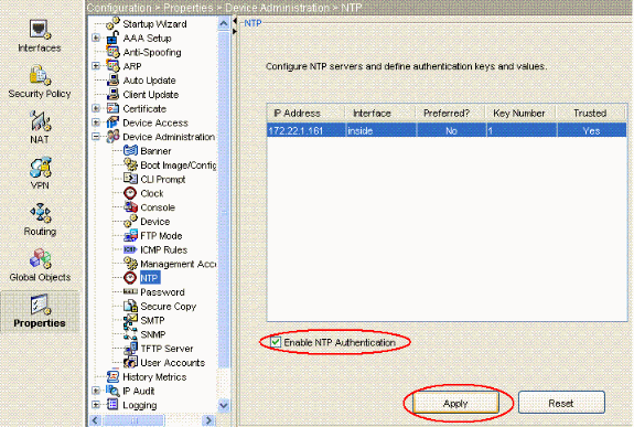
Aktivieren Sie jetzt das Kontrollkästchen NTP-Authentifizierung aktivieren, und klicken Sie auf Anwenden, um die NTP-Konfigurationsaufgabe abzuschließen.
Konfiguration der ASA1-CLI
| ASA 1 |
|---|
ASA#show run : Saved ASA Version 7.1(1) ! hostname ASA1 domain-name default.domain.invalid enable password 8Ry2YjIyt7RRXU24 encrypted names ! interface Ethernet0 nameif outside security-level 0 ip address 10.10.10.1 255.255.255.0 !--- Configure the outside interface. ! interface Ethernet1 nameif inside security-level 100 ip address 172.22.1.163 255.255.255.0 !--- Configure the inside interface. ! !-- Output suppressed ! passwd 2KFQnbNIdI.2KYOU encrypted ftp mode passive dns server-group DefaultDNS domain-name default.domain.invalid access-list inside_nat0_outbound extended permit ip 172.22.1.0 255.255.255.0 172 .16.1.0 255.255.255.0 !--- This access list (inside_nat0_outbound) is used !--- with the nat zero command. This prevents traffic which !--- matches the access list from undergoing network address translation (NAT). !--- The traffic specified by this ACL is traffic that is to be encrypted and !--- sent across the VPN tunnel. This ACL is intentionally !--- the same as (outside_cryptomap_20). !--- Two separate access lists should always be used in this configuration. access-list outside_cryptomap_20 extended permit ip 172.22.1.0 255.255.255.0 172 .16.1.0 255.255.255.0 !--- This access list (outside_cryptomap_20) is used !--- with the crypto map outside_map !--- to determine which traffic should be encrypted and sent !--- across the tunnel. !--- This ACL is intentionally the same as (inside_nat0_outbound). !--- Two separate access lists should always be used in this configuration. pager lines 24 mtu inside 1500 mtu outside 1500 no failover asdm image flash:/asdm-511.bin !--- Enter this command to specify the location of the ASDM image. asdm history enable arp timeout 14400 nat (inside) 0 access-list inside_nat0_outbound !--- NAT 0 prevents NAT for networks specified in !--- the ACL inside_nat0_outbound. route outside 0.0.0.0 0.0.0.0 10.10.10.2 1 timeout xlate 3:00:00 timeout conn 1:00:00 half-closed 0:10:00 udp 0:02:00 icmp 0:00:02 timeout sunrpc 0:10:00 h323 0:05:00 h225 1:00:00 mgcp 0:05:00 timeout mgcp-pat 0:05:00 sip 0:30:00 sip_media 0:02:00 timeout uauth 0:05:00 absolute http server enable !--- Enter this command in order to enable the HTTPS server !--- for ASDM. http 172.22.1.1 255.255.255.255 inside !--- Identify the IP addresses from which the security appliance !--- accepts HTTPS connections. no snmp-server location no snmp-server contact !--- PHASE 2 CONFIGURATION ---! !--- The encryption types for Phase 2 are defined here. crypto ipsec transform-set ESP-AES-256-SHA esp-aes-256 esp-sha-hmac !--- Define the transform set for Phase 2. crypto map outside_map 20 match address outside_cryptomap_20 !--- Define which traffic should be sent to the IPsec peer. crypto map outside_map 20 set peer 10.20.20.1 !--- Sets the IPsec peer crypto map outside_map 20 set transform-set ESP-AES-256-SHA !--- Sets the IPsec transform set "ESP-AES-256-SHA" !--- to be used with the crypto map entry "outside_map". crypto map outside_map interface outside !--- Specifies the interface to be used with !--- the settings defined in this configuration. !--- PHASE 1 CONFIGURATION ---! !--- This configuration uses isakmp policy 10. !--- Policy 65535 is included in the config by default. !--- The configuration commands here define the Phase !--- 1 policy parameters that are used. isakmp enable outside isakmp policy 10 authentication pre-share isakmp policy 10 encryption aes-256 isakmp policy 10 hash sha isakmp policy 10 group 5 isakmp policy 10 lifetime 86400 isakmp policy 65535 authentication pre-share isakmp policy 65535 encryption 3des isakmp policy 65535 hash sha isakmp policy 65535 group 2 isakmp policy 65535 lifetime 86400 tunnel-group 10.20.20.1 type ipsec-l2l !--- In order to create and manage the database of connection-specific !--- records for ipsec-l2l—IPsec (LAN-to-LAN) tunnels, use the command !--- tunnel-group in global configuration mode. !--- For L2L connections the name of the tunnel group MUST be the IP !--- address of the IPsec peer. tunnel-group 10.20.20.1 ipsec-attributes pre-shared-key * !--- Enter the pre-shared-key in order to configure the !--- authentication method. telnet timeout 5 ssh timeout 5 console timeout 0 ! class-map inspection_default match default-inspection-traffic ! ! policy-map global_policy class inspection_default inspect dns maximum-length 512 inspect ftp inspect h323 h225 inspect h323 ras inspect netbios inspect rsh inspect rtsp inspect skinny inspect esmtp inspect sqlnet inspect sunrpc inspect tftp inspect sip inspect xdmcp ! service-policy global_policy global !--- Define the NTP server autentication-key,Trusted-key !--- and the NTP server address for configuring NTP. ntp authentication-key 1 md5 * ntp trusted-key 1 !--- The NTP server source is to be mentioned as inside for ASA1 ntp server 172.22.1.161 key 1 source inside Cryptochecksum:ce7210254f4a0bd263a9072a4ccb7cf7 : end |
In diesem Video, das in der Cisco Support Community gezeigt wird,![]() wird das Verfahren zur Konfiguration von ASA als NTP-Client vorgeführt:
wird das Verfahren zur Konfiguration von ASA als NTP-Client vorgeführt:
Konfiguration der ASA2-CLI
| ASA 2 |
|---|
ASA Version 7.1(1) ! hostname ASA2 domain-name default.domain.invalid enable password 8Ry2YjIyt7RRXU24 encrypted names ! interface Ethernet0 nameif outside security-level 0 ip address 10.20.20.1 255.255.255.0 ! interface Ethernet1 nameif inside security-level 100 ip address 172.16.1.1 255.255.255.0 ! passwd 2KFQnbNIdI.2KYOU encrypted ftp mode passive dns server-group DefaultDNS domain-name default.domain.invalid access-list inside_nat0_outbound extended permit ip 172.16.1.0 255.255.255.0 172 .22.1.0 255.255.255.0 !--- Note that this ACL is a mirror of the inside_nat0_outbound !--- ACL on ASA1. access-list outside_cryptomap_20 extended permit ip 172.16.1.0 255.255.255.0 172 .22.1.0 255.255.255.0 !--- Note that this ACL is a mirror of the outside_cryptomap_20 !--- ACL on ASA1. pager lines 24 mtu inside 1500 mtu outside 1500 no failover asdm image flash:/asdm-511.bin no asdm history enable arp timeout 14400 nat (inside) 0 access-list inside_nat0_outbound timeout xlate 3:00:00 timeout conn 1:00:00 half-closed 0:10:00 udp 0:02:00 icmp 0:00:02 timeout sunrpc 0:10:00 h323 0:05:00 h225 1:00:00 mgcp 0:05:00 timeout mgcp-pat 0:05:00 sip 0:30:00 sip_media 0:02:00 timeout uauth 0:05:00 absolute http server enable http 0.0.0.0 0.0.0.0 inside no snmp-server location no snmp-server contact crypto ipsec transform-set ESP-AES-256-SHA esp-aes-256 esp-sha-hmac crypto map outside_map 20 match address outside_cryptomap_20 crypto map outside_map 20 set peer 10.10.10.1 crypto map outside_map 20 set transform-set ESP-AES-256-SHA crypto map outside_map interface outside isakmp enable outside isakmp policy 10 authentication pre-share isakmp policy 10 encryption aes-256 isakmp policy 10 hash sha isakmp policy 10 group 5 isakmp policy 10 lifetime 86400 tunnel-group 10.10.10.1 type ipsec-l2l tunnel-group 10.10.10.1 ipsec-attributes pre-shared-key * telnet timeout 5 ssh timeout 5 console timeout 0 ! class-map inspection_default match default-inspection-traffic ! ! policy-map global_policy class inspection_default inspect dns maximum-length 512 inspect ftp inspect h323 h225 inspect h323 ras inspect netbios inspect rsh inspect rtsp inspect skinny inspect esmtp inspect sqlnet inspect sunrpc inspect tftp inspect sip inspect xdmcp ! service-policy global_policy global !--- Define the NTP server autentication-key,Trusted-key !--- and the NTP server address for configuring NTP. ntp authentication-key 1 md5 * ntp trusted-key 1 !--- The NTP server source is to be mentioned as outside for ASA2. ntp server 172.22.1.161 key 1 source outside Cryptochecksum:d5e2ee898f5e8bd28e6f027aeed7f41b : end ASA# |
Überprüfung
Diese Abschnitt enthält Informationen, mit denen Sie überprüfen können, ob Ihre Konfiguration ordnungsgemäß funktioniert.
Einige Befehle des Typs show werden vom Tool Output Interpreter unterstützt (nur für registrierte Kunden), mit dem sich Analysen der Ausgabe von Befehlen des Typs show abrufen lassen.
-
show ntp status (NTP-Status anzeigen): Zeigt die NTP-Uhrzeitinformationen an.
ASA1#show ntp status
Clock is synchronized, stratum 2, reference is 172.22.1.161
nominal freq is 99.9984 Hz, actual freq is 99.9983 Hz, precision is 2**6
reference time is ccf22b77.f7a6e7b6 (13:28:23.967 UTC Tue Dec 16 2008)
clock offset is 34.8049 msec, root delay is 4.78 msec
root dispersion is 60.23 msec, peer dispersion is 25.41 msec
-
show ntp associations [detail] - Zeigt die konfigurierten Netzwerkzeit-Serverzuordnungen an.
ASA1#show ntp associations detail
172.22.1.161 configured, authenticated, our_master, sane, valid, stratum 1
ref ID .LOCL., time ccf2287d.3668b946 (13:15:41.212 UTC Tue Dec 16 2008)
our mode client, peer mode server, our poll intvl 64, peer poll intvl 64
root delay 0.00 msec, root disp 0.03, reach 7, sync dist 23.087
delay 4.52 msec, offset 9.7649 msec, dispersion 20.80
precision 2**19, version 3
org time ccf22896.f1a4fca3 (13:16:06.943 UTC Tue Dec 16 2008)
rcv time ccf22896.efb94b28 (13:16:06.936 UTC Tue Dec 16 2008)
xmt time ccf22896.ee5691dc (13:16:06.931 UTC Tue Dec 16 2008)
filtdelay =     4.52    4.68    4.61    0.00    0.00    0.00    0.00    0.00
filtoffset =    9.76    7.09    3.85    0.00    0.00    0.00    0.00    0.00
filterror =    15.63   16.60   17.58 14904.3 14904.3 14904.3 14904.3 14904.3
Fehlerbehebung
In diesem Abschnitt finden Sie Informationen zur Behebung von Fehlern in Ihrer Konfiguration.
Befehle für die Fehlerbehebung
Einige Befehle des Typs show werden vom Tool Output Interpreter unterstützt (nur für registrierte Kunden), mit dem sich Analysen der Ausgabe von Befehlen des Typs show abrufen lassen.
Hinweis: Bevor Sie Debug-Befehle ausgeben, lesen Sie Wichtige Informationen zu Debug-Befehlen.
-
debug ntp validation (debug ntp-Gültigkeit): Zeigt die Gültigkeit der NTP-Peer-Uhr an.
Dies ist die Debug-Ausgabe der Schlüsselfehlanpassung:
NTP: packet from 172.22.1.161 failed validity tests 10
 	  Authentication failed
-
debug ntp packet: Zeigt NTP-Paketinformationen an.
Wenn der Server nicht antwortet, wird auf der ASA nur das NTP-xmit-Paket ohne NTP-rcv-Paket angezeigt.
ASA1# NTP: xmit packet to 172.22.1.161:
 leap 0, mode 3, version 3, stratum 2, ppoll 64
 rtdel 012b (4.562), rtdsp 0cb6 (49.652), refid ac1601a1 (172.22.1.161)
 ref ccf22916.f1211384 (13:18:14.941 UTC Tue Dec 16 2008)
 org ccf22916.f426232d (13:18:14.953 UTC Tue Dec 16 2008)
 rec ccf22916.f1211384 (13:18:14.941 UTC Tue Dec 16 2008)
 xmt ccf22956.f08ee8b4 (13:19:18.939 UTC Tue Dec 16 2008)
NTP: rcv packet from 172.22.1.161 to 172.22.1.163 on inside:
 leap 0, mode 4, version 3, stratum 1, ppoll 64
 rtdel 0000 (0.000), rtdsp 0002 (0.031), refid 4c4f434c (76.79.67.76)
 ref ccf2293d.366a4808 (13:18:53.212 UTC Tue Dec 16 2008)
 org ccf22956.f08ee8b4 (13:19:18.939 UTC Tue Dec 16 2008)
 rec ccf22956.f52e480e (13:19:18.957 UTC Tue Dec 16 2008)
 xmt ccf22956.f5688c29 (13:19:18.958 UTC Tue Dec 16 2008)
 inp ccf22956.f982bcd9 (13:19:18.974 UTC Tue Dec 16 2008)
Zugehörige Informationen
Revisionsverlauf
| Überarbeitung | Veröffentlichungsdatum | Kommentare |
|---|---|---|
1.0 |
16-Dec-2008 |
Erstveröffentlichung |
 Feedback
Cisco kontaktieren
- Eine Supportanfrage öffnen

- (Erfordert einen Cisco Servicevertrag)