Verbesserter Durchsatz für Catalyst 8000V mit Multi-TxQs in AWS
Download-Optionen
Inklusive Sprache
In dem Dokumentationssatz für dieses Produkt wird die Verwendung inklusiver Sprache angestrebt. Für die Zwecke dieses Dokumentationssatzes wird Sprache als „inklusiv“ verstanden, wenn sie keine Diskriminierung aufgrund von Alter, körperlicher und/oder geistiger Behinderung, Geschlechtszugehörigkeit und -identität, ethnischer Identität, sexueller Orientierung, sozioökonomischem Status und Intersektionalität impliziert. Dennoch können in der Dokumentation stilistische Abweichungen von diesem Bemühen auftreten, wenn Text verwendet wird, der in Benutzeroberflächen der Produktsoftware fest codiert ist, auf RFP-Dokumentation basiert oder von einem genannten Drittanbieterprodukt verwendet wird. Hier erfahren Sie mehr darüber, wie Cisco inklusive Sprache verwendet.
Informationen zu dieser Übersetzung
Cisco hat dieses Dokument maschinell übersetzen und von einem menschlichen Übersetzer editieren und korrigieren lassen, um unseren Benutzern auf der ganzen Welt Support-Inhalte in ihrer eigenen Sprache zu bieten. Bitte beachten Sie, dass selbst die beste maschinelle Übersetzung nicht so genau ist wie eine von einem professionellen Übersetzer angefertigte. Cisco Systems, Inc. übernimmt keine Haftung für die Richtigkeit dieser Übersetzungen und empfiehlt, immer das englische Originaldokument (siehe bereitgestellter Link) heranzuziehen.
Inhalt
Einleitung
In diesem Dokument wird beschrieben, wie Sie Multi-TXQs auf Catalyst 8000V in AWS-Umgebungen aktivieren und verwenden können, um die Durchsatzleistung zu verbessern.
Hintergrundinformationen
Das Vorhandensein mehrerer Warteschlangen vereinfacht und beschleunigt die Zuordnung eingehender und ausgehender Pakete zu einer bestimmten vCPU. Die Verwendung von Multi-TXQs auf Catalyst 8000V ermöglicht eine effiziente Kernauslastung über die verfügbaren zugewiesenen Kerne der Datenflugzeuge hinweg, was zu einer höheren Durchsatzleistung führt. Dieser Artikel bietet einen kurzen Überblick über die Funktionsweise und Konfiguration von Multi-TXQs, zeigt Beispiele für CLI-Konfigurationen für autonome und SD-WAN Catalyst 8000V-Bereitstellungen und gibt einen Überblick über die Befehle zur Fehlerbehebung, um Leistungsengpässe zu ermitteln.
Catalyst 8000V-Verhalten bei Nichtverwendung von Multi-TxQs
Bis zur Softwareversion 17.18 werden Pakete, die in Catalyst 8000V eingehen, unabhängig von den Datenströmen an alle vCPUs (Packet Processing Cores) verteilt. Sobald PP die Paketverarbeitung abgeschlossen hat, wird der Flow-Auftrag wiederhergestellt und an eine Schnittstelle gesendet.
Bevor das Paket in eine Senderwarteschlange (TxQ) gestellt wird, erstellt der Catalyst 8000V eine TxQ pro Schnittstelle. Wenn daher nur eine Ausgangsschnittstelle verfügbar ist, werden mehrere Flows in eine TxQ übertragen.
Der Catalyst 8000V kann diesen Multi-TxQ-Prozess nur dann nutzen, wenn eine Schnittstelle verfügbar ist. Dies führt zu Engpässen bei der Durchsatzleistung und einer ungleichmäßigen Lastverteilung auf die verfügbaren Kerne der Datenflugzeuge. Wenn nur eine Ausgangsschnittstelle zum Übertragen von Daten aus der C8000V-Instanz verwendet wird, steht nur eine TxQ zur Verfügung, um Netzwerkverkehr zu übertragen und möglicherweise dazu zu führen, dass Pakete verworfen werden, da sich die einzelne Warteschlange schneller füllt.
Das TxQ-Architekturmodell für Catalyst 8000V, das in AWS bereitgestellt wird, finden Sie hier in Abbildung 1.
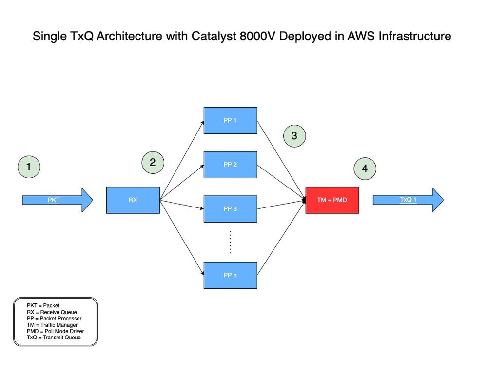
Abbildung 1: Einzelnes TxQ-Architekturmodell für Catalyst 8000V in AWS.
-
- Ein Netzwerkpaket (PKT) durchläuft eine vPC und wird an der Eingangsschnittstelle eines C8000V empfangen.
- Die PKT wird in eine Empfangswarteschlange (RX) gestellt und dann an eine Paketprozessor (PP)-Engine weitergeleitet, die von einem Algorithmus bestimmt wird.
- Nachdem der Packet Processor (PP) das Paket verarbeitet hat, sendet er das Paket an Traffic Manager (TM).
- Am Ende der TM-Verarbeitung ist ein Kern für die Platzierung des Pakets in dem einen verfügbaren TxQ verantwortlich, der dann an die Ausgangsschnittstelle des Catalyst 8000V weitergeleitet wird.
Was sind Multi-TXQs in AWS-Infrastruktur?
AWS ENA bietet mehrere Warteschlangen für Übertragungen (Multi-TxQs), um den internen Overhead zu reduzieren und die Skalierbarkeit zu erhöhen. Das Vorhandensein mehrerer Warteschlangen vereinfacht und beschleunigt die Zuordnung eingehender und ausgehender Pakete zu einer bestimmten vCPU. Das AWS- und DPDK-Netzwerkreferenzmodell ist datenflussbasiert, wobei jede vCPU einen Datenfluss verarbeitet und Pakete aus diesem Datenfluss an eine zugewiesene Übertragungswarteschlange (TxQ) überträgt. Das RX-/TX-Warteschlangenpaar für jede vCPU ist basierend auf dem datenflussbasierten Modell gültig.
Da der Catalyst 8000V NICHT flussbasiert ist, gilt die Anweisung "RX/TX queue pair for each vCPU" nicht für den Catalyst 8000V.
In diesem Fall sind RX/TX-Warteschlangen nicht pro vCPU, sondern pro Schnittstelle. RX-/TX-Warteschlangen fungieren als Schnittstellen zwischen der Anwendung (Catalyst 8000V) und der AWS-Infrastruktur bzw. -Hardware zum Senden von Daten-/Netzwerkdatenverkehr. AWS steuert, wie schnell und wie viele RX/TX-Warteschlangen pro Schnittstelle pro Instanz verfügbar sind.
Der Catalyst 8000V muss über mehrere Schnittstellen verfügen, um mehrere TxQs erstellen zu können. Um die Flussreihenfolge bei mehreren Flows an einer Schnittstelle beizubehalten (sobald der Catalyst 8000V nach diesem Prozess mehrere TxQs aktiviert hat), hasht der Catalyst 8000V Flows auf Basis der 5 Tupel, um die passende TxQ auszuwählen. Ein Benutzer kann auf dem Catalyst 8000V mehrere Schnittstellen erstellen, indem er dieselbe physische NIC verwendet, die der Instanz über Loopback-Schnittstellen oder sekundäre IP-Adressen zugeordnet ist.
In Abbildung 2 sehen Sie, wie ein Paket mithilfe der Multi-TxQ-Architektur mit Catalyst 8000V in AWS verarbeitet wird.
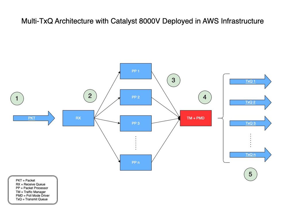
Abbildung 2: Multi-TxQ-Architekturmodell für Catalyst 8000V in AWS.
-
- Ein Netzwerkpaket (PKT) durchläuft eine vPC und wird an der Eingangsschnittstelle eines C8000V empfangen.
- Die PKT wird in eine Empfangswarteschlange (RX) gestellt und dann an eine Paketprozessor (PP)-Engine weitergeleitet, die von einem Algorithmus bestimmt wird.
- Nachdem der Packet Processor (PP) das Paket verarbeitet hat, sendet er das Paket an Traffic Manager (TM).
- Am Ende der TM-Verarbeitung schaut das TM vor der Übergabe des Pakets in eine Übermittlungswarteschlange (TxQ) auf den Paket-Header und hasht das Paket (wie im nächsten Abschnitt erläutert). Eine weitere Komponente, der Poll Mode Driver (PMD), wird verwendet, um die Anzahl der von der Instanz unterstützten TXQs zu konfigurieren. Ein Core ist für die TM + PMD Funktion reserviert, die das Hashing und Senden des Pakets an den zugewiesenen TxQ übernimmt.
- Der TxQ wird basierend auf den fünf gehashten Tupeln und modulo mit der Anzahl der von der Instanz unterstützten TxQ ausgewählt. Pakete werden in den ausgewählten TxQ gestellt und an die Ausgangsschnittstelle des Catalyst 8000V weitergeleitet.
Wie Datenverkehr in Multi-TxQs gehasht wird
Am Ende der TM-Verarbeitung, wie in Schritt 4 in Abbildung 2 gezeigt, prüft das TM vor dem Platzieren des Pakets in einem TxQ den Paket-Header und extrahiert die 5 Tupel (Zieladresse, Quelladresse, Protokoll, Zielport und Quellport) und hasht das Paket in einen TxQ.
Der TxQ wird basierend auf den fünf gehashten Tupeln und modulo mit der Anzahl der von der Instanz unterstützten TxQ ausgewählt.
Catalyst 8000V-Softwareversionen mit Unterstützung für Multi-TxQs
AWS EC2-Instanzen desselben Instanzenfamilientyps unterstützen je nach Instanzgröße unterschiedliche TXQs. Der C8000V begann mit der Unterstützung mehrerer TxQs, beginnend mit IOS® XE 17.7.
Ab IOS® XE 17.7 unterstützt der C8000V mehrere TxQs auf dem C5n.9xlarge, die bis zu 8 TXQs haben können.
Ab IOS® XE 17.9 unterstützt der C8000V die Größe großer C5n.18xlarge-Instanzen, die bis zu 12 TXQs aufweisen können (50 % mehr als C5n.9xlarge).
Obwohl Multi-TxQ von IOS® XE 17.7 unterstützt wird, wird DRINGEND empfohlen, IOS® XE 17.9 sowohl für den Softwarelebenszyklus als auch für höhere Durchsatzleistungen mit Unterstützung von 12 TxQ zu verwenden.
So entwickeln Sie das IP-Adressierungsschema für die Berechnung des Hashs
Um den Datenverkehr gleichmäßig zwischen allen verfügbaren TxQs zu hash, müssen spezielle IP-Adressen verwendet werden, wenn der Catalyst 8000V IPsec/GRE-Tunnel terminiert.
Es stehen öffentliche Skripte zur Verfügung, um diese speziellen IP-Adressen zu generieren, die für die Konfiguration der Catalyst 8000V-Schnittstellen verwendet werden, die für die Terminierung dieser Tunnel verantwortlich sind. Dieser Abschnitt enthält Anweisungen zum Herunterladen und Verwenden der Skripte zum Entwickeln der erforderlichen IP-Adressen für Multi-TxQ-Hashing.
Wenn der Catalyst 8000V Klartextdatenverkehr wie TCP/UDP verarbeitet, ist kein spezielles IP-Adressierungsschema erforderlich.
Die Originalanleitung finden Sie hier: https://github.com/CiscoDevNet/python-c8000v-aws-multitx-queues/

Anmerkung: Bei Catalyst 8000V mit 17.18 oder höher werden Pakete unterschiedlich verteilt. Daher muss ein anderer Hashing-Algorithmus verwendet werden.
Voraussetzungen
- Muss über Linux/MacOS oder eine Windows-Maschine verfügen, die Python-Skripte ausführen kann.
- Stellen Sie sicher, dass die Python-Version 3.8.9 oder höher ist. Python-Version mit 'python3 —version' überprüfen
- Installieren Sie PIP, wenn es nicht bereits installiert ist. Falls nicht, führen Sie Folgendes aus:
- curl https://bootstrap.pypa.io/get-pip.py -o get-pip.py
- python3 get-pip.py
Mit dem Befehl 'python3 —version' können Sie überprüfen, welche Python-Version Ihr Rechner verwendet.
user@computer ~ % python3 --version

Python 3.9.6
Sobald die Python-Version überprüft wurde und ausgeführt wird, eine Version, die mindestens 3.8.9 entspricht, installieren Sie die neueste Version von PIP.
user@computer ~ % curl https://bootstrap.pypa.io/get-pip.py -o get-pip.py

  % Total    % Received % Xferd  Average Speed   Time    Time     Time  Current

                                 Dload  Upload   Total   Spent    Left  Speed

100 2570k  100 2570k    0     0  6082k      0 --:--:-- --:--:-- --:--:-- 6135k
user@computer ~ % python3 get-pip.py

Defaulting to user installation because normal site-packages is not writeable
Collecting pip
  Downloading pip-23.3.1-py3-none-any.whl.metadata (3.5 kB)
Downloading pip-23.3.1-py3-none-any.whl (2.1 MB)

   ━━━━━━━━━━━━━━━━━━━━━━━━━━━━━━━━━━━━━━━━ 2.1/2.1 MB 7.4 MB/s eta 0:00:00

Installing collected packages: pip

  WARNING: The scripts pip, pip3 and pip3.9 are installed in '/Users/name/Library/Python/3.9/bin' which is not on PATH.

  Consider adding this directory to PATH or, if you prefer to suppress this warning, use --no-warn-script-location.

Successfully installed pip-23.3.1

[notice] A new release of pip is available: 21.2.4 -> 23.3.1
[notice] To update, run: /Applications/Xcode.app/Contents/Developer/usr/bin/python3 -m pip install --upgrade pip
Virtuelle Umgebung erstellen
Erstellen Sie nach der Installation der erforderlichen Komponenten die virtuelle Umgebung, und laden Sie das Hashing-Skript für die IP-Adresse herunter, mit dem das eindeutige IP-Adressschema für Multi-TxQ erstellt wird.
Zusammenfassung der Befehle:
- python3 -m venv c8kv-hash
- cd c8kv-hash
- Quellfach/aktivieren
- git clone https://github.com/CiscoDevNet/python-c8000v-aws-multitx-queues/
- cd c8kv-aws-pmd-hash
- python3 -m pip install —upgrade pip
- pip install -r requirements.txt
Virtuelle Umgebungen in Python werden verwendet, um isolierte Arbeitsbereiche zu erstellen, die sich nicht auf andere Projekte oder Abhängigkeiten auswirken. Erstellen Sie die virtuelle Umgebung "c8kv-hash" mit dem folgenden Befehl:
user@computer Desktop % python3 -m venv c8kv-hashNavigieren Sie innerhalb der virtuellen Umgebung zum Ordner 'c8kv-hash' (zuvor erstellt).
user@computer Desktop % cd c8kv-hashAktivieren der virtuellen Umgebung
user@computer c8kv-hash % source bin/activateKlonen Sie das Repository, das das Multi-TxQ-Hashing-Python-Skript enthält.
(c8kv-hash) user@computer c8kv-hash % git clone https://github.com/CiscoDevNet/python-c8000v-aws-multitx-queues.git

Cloning into 'c8kv-aws-pmd-hash'...
remote: Enumerating objects: 82, done.
remote: Counting objects: 100% (82/82), done.
remote: Compressing objects: 100% (59/59), done.
remote: Total 82 (delta 34), reused 57 (delta 19), pack-reused 0
Receiving objects: 100% (82/82), 13.01 KiB | 2.60 MiB/s, done.
Resolving deltas: 100% (34/34), done.
Sobald das Repository geklont wurde, navigieren Sie zum Ordner 'c8kv-aws-pmd-hash'. Da sich dieser in der erstellten virtuellen Umgebung befindet, installieren Sie die neueste Version von PIP.
(c8kv-hash) user@computer c8kv-hash % cd c8kv-aws-pmd-hash
(c8kv-hash) user@computer c8kv-aws-pmd-hash % python3 -m pip install --upgrade pip

Requirement already satisfied: pip in /Users/name/Desktop/c8kv-hash/lib/python3.9/site-packages (21.2.4)
Collecting pip
  Downloading pip-23.3.1-py3-none-any.whl (2.1 MB)
     |████████████████████████████████| 2.1 MB 2.7 MB/s
Installing collected packages: pip
  Attempting uninstall: pip
    Found existing installation: pip 21.2.4
    Uninstalling pip-21.2.4:
      Successfully uninstalled pip-21.2.4
Successfully installed pip-23.3.1
Installieren Sie nach dem PIP-Upgrade die Abhängigkeiten aus der Datei requirements.txt im Ordner.
(c8kv-hash) user@computer c8kv-aws-pmd-hash % pip install -r requirements.txt
Collecting crc32c==2.3 (from -r requirements.txt (line 1))
  Downloading crc32c-2.3-cp39-cp39-macosx_11_0_arm64.whl (27 kB)
Installing collected packages: crc32c
Successfully installed crc32c-2.3
Die virtuelle Umgebung ist jetzt auf dem neuesten Stand und kann zum Generieren des IP-Adressschemas für Multi-TxQ verwendet werden.
Berechnung des IP-Adressschemas mithilfe des Python-Hash-Index-Skripts für die Versionen 17.7 und 17.8 (herabsetzend)

Anmerkung: 7.7 UND 17.8 HASHSKRIPTE SOLLEN BALD VERALTET WERDEN. ES WIRD DRINGEND EMPFOHLEN, 17.9-HASHSCRIPT ZU VERWENDEN.
Zusammenfassung der Befehle:
- python3 c8kv_multitxq_hash.py —old_crc 1 —dest_network 192.168.1.0/24 —src_network 192.168.2.0/24 --unique_hash 1
'—old_crc 1' generiert einen Hash-Index basierend auf Version 17.7 und 17.8 mit Modulo 8, der mit dem unterstützten PMD TXQ übereinstimmt (NICHT ändern).
'—dest_network' definiert das Zielnetzwerkadressen-Subnetz (entsprechend Ihres Netzwerk-IP-Adressenschemas ändern).
'—src_network' definiert das Subnetz der Quellnetzwerkadresse (entsprechend Ihres Netzwerk-IP-Adressenschemas ändern).
'—unique_hash 1' generiert einen Satz (8 Paare für 8 TXQs) eindeutig gehashter IP-Adressen. Dies kann geändert werden.
(c8kv-hash) user@computer c8kv-aws-pmd-hash % python3 c8kv_multitxq_hash.py --old_crc 1 --dest_network 192.168.1.0/24 --src_network 192.168.2.0/24  --unique_hash 1

Dest:            Src:             Prot  dstport  srcport          Hash: Rev-hash:

192.168.1.0      192.168.2.0      2     5
192.168.1.0      192.168.2.1      2     7
192.168.1.0      192.168.2.2      2     1
192.168.1.0      192.168.2.3      2     3
192.168.1.0      192.168.2.4      2     5
192.168.1.0      192.168.2.5      2     7
192.168.1.0      192.168.2.6      2     1
192.168.1.0      192.168.2.7      2     3
192.168.1.0      192.168.2.8      2     5
192.168.1.0      192.168.2.9      2     7
192.168.1.0      192.168.2.10     2     1
.
. ### trimmed output ###
.
192.168.1.255    192.168.2.247    5     2
192.168.1.255    192.168.2.248    5     4
192.168.1.255    192.168.2.249    5     6
192.168.1.255    192.168.2.250    5     0
192.168.1.255    192.168.2.251    5     2
192.168.1.255    192.168.2.252    5     4
192.168.1.255    192.168.2.253    5     6
192.168.1.255    192.168.2.254    5     0
192.168.1.255    192.168.2.255    5     2

Unique hash:

------ Tunnels set 0 ---------

192.168.1.37<===>192.168.2.37<===>0
192.168.1.129<===>192.168.2.129<===>1
192.168.1.36<===>192.168.2.36<===>2
192.168.1.128<===>192.168.2.128<===>3
192.168.1.39<===>192.168.2.39<===>4
192.168.1.131<===>192.168.2.131<===>5
192.168.1.38<===>192.168.2.38<===>6
192.168.1.130<===>192.168.2.130<===>7
Berechnung des IP-Adressierungsschemas mithilfe des Python-Hash-Index-Skripts für Versionen 17.9 und höher
Zusammenfassung der Befehle:
- python3 c8kv_multitxq_hash.py —dest_network 192.168.1.0/24 —src_network 192.168.2.0/24 —prot udp —src_port 12346 —dst_port 12346 —unique_hash 1
Beachten Sie, dass das Skript in IOS® XE, Version 17.9 und höher, modulo 12 ohne die Option —old_crc verwendet, die mit der unterstützten PMD TXQ übereinstimmt.
'—dest_network' definiert das Zielnetzwerkadressen-Subnetz (entsprechend Ihres Netzwerk-IP-Adressenschemas ändern).
'—src_network' definiert das Subnetz der Quellnetzwerkadresse (entsprechend Ihres Netzwerk-IP-Adressenschemas ändern).
'—prot udp' definiert das verwendete Protokoll. Der Benutzer kann den Protokollparameter als "gre" oder "tcp" oder "udp" oder einen beliebigen Dezimalwert angeben (OPTIONAL)
'—src_port' definiert den verwendeten Quellport (OPTIONAL)
'—dst_port' definiert den verwendeten Zielport (OPTIONAL)
'—unique_hash 1' generiert einen Satz (12 Paare für 12 TXQs) eindeutig gehashter IP-Adressen. Dies kann geändert werden.
(c8kv-hash) user@computer c8kv-aws-pmd-hash % python3 c8kv_multitxq_hash.py --dest_network 192.168.1.0/24 --src_network 192.168.2.0/24 --prot udp --src_port 12346 --dst_port 12346 --unique_hash 1

Dest:            Src:             Prot  dstport  srcport          Hash: Rev-hash:

192.168.1.0      192.168.2.0      17    12346    12346       ==>    4        4       <-- Unique Hash Value
192.168.1.0      192.168.2.1      17    12346    12346       ==>    4        4
192.168.1.0      192.168.2.2      17    12346    12346       ==>    8        8       <-- Unique Hash Value
192.168.1.0      192.168.2.3      17    12346    12346       ==>    0        0       <-- Unique Hash Value
192.168.1.0      192.168.2.4      17    12346    12346       ==>    0        0
192.168.1.0      192.168.2.5      17    12346    12346       ==>    0        0
192.168.1.0      192.168.2.6      17    12346    12346       ==>    4        4
192.168.1.0      192.168.2.7      17    12346    12346       ==>    0        0
192.168.1.0      192.168.2.8      17    12346    12346       ==>    9        9       <-- Unique Hash Value
192.168.1.0      192.168.2.9      17    12346    12346       ==>    9        9
192.168.1.0      192.168.2.10     17    12346    12346       ==>    9        9
192.168.1.0      192.168.2.11     17    12346    12346       ==>    1        1       <-- Unique Hash Value
192.168.1.0      192.168.2.12     17    12346    12346       ==>    1        1
.
. ### trimmed output ###
.
192.168.1.255    192.168.2.250    17    12346    12346       ==>    1        1
192.168.1.255    192.168.2.251    17    12346    12346       ==>    1        1
192.168.1.255    192.168.2.252    17    12346    12346       ==>    9        9
192.168.1.255    192.168.2.253    17    12346    12346       ==>    1        1
192.168.1.255    192.168.2.254    17    12346    12346       ==>    5        5       <-- Unique Hash Value
192.168.1.255    192.168.2.255    17    12346    12346       ==>    9        9

Unique hash:

------ Tunnels set 0 ---------

192.168.1.38 <===> 192.168.2.38<===>0
192.168.1.37 <===> 192.168.2.37<===>1
192.168.1.53 <===> 192.168.2.53<===>2
192.168.1.39 <===> 192.168.2.39<===>3
192.168.1.48 <===> 192.168.2.48<===>4
192.168.1.58 <===> 192.168.2.58<===>5
192.168.1.42 <===> 192.168.2.42<===>6
192.168.1.46 <===> 192.168.2.46<===>7
192.168.1.40 <===> 192.168.2.40<===>8
192.168.1.43 <===> 192.168.2.43<===>9
192.168.1.36 <===> 192.168.2.36<===>10
192.168.1.56 <===> 192.168.2.56<===>11
Topologie- und CLI-Beispielkonfiguration mit 8 TXQs mit Loopback-Schnittstellen

Abbildung 3: Beispieltopologie, die acht TxQs über Loopback-Schnittstellen verwendet.
Dies ist eine CLI-Beispielkonfiguration für "c8kv-out" (Abbildung 3), die acht IPsec-Tunnel mit Loopback-Schnittstellen erstellt, wobei die berechneten gehashten IP-Adressen (192.168.1.X) aus dem vorherigen Abschnitt verwendet werden.
Eine ähnliche Konfiguration würde für den anderen Router-Endpunkt (c8kv-peer) mit den verbleibenden acht berechneten Hash-IP-Adressen (192.168.2.X) gelten.
ip cef load-sharing algorithm include-ports source destination 00ABC123

crypto keyring tunnel0
  local-address Loopback0
  pre-shared-key address 192.168.2.37 key cisco
crypto keyring tunnel1
  local-address Loopback1
  pre-shared-key address 192.168.2.129 key cisco
crypto keyring tunnel2
  local-address Loopback2
  pre-shared-key address 192.168.2.36 key cisco
crypto keyring tunnel3
  local-address Loopback3
  pre-shared-key address 192.168.2.128 key cisco
crypto keyring tunnel4
  local-address Loopback4
  pre-shared-key address 192.168.2.39 key cisco
crypto keyring tunnel5
  local-address Loopback5
  pre-shared-key address 192.168.2.131 key cisco
crypto keyring tunnel6
  local-address Loopback6
  pre-shared-key address 192.168.2.38 key cisco
crypto keyring tunnel7
  local-address Loopback7
  pre-shared-key address 192.168.2.130 key cisco

crypto isakmp policy 200
 encryption aes
 hash sha
 authentication pre-share
 group 16
 lifetime 28800

crypto isakmp profile isakmp-tunnel0
   keyring tunnel0
   match identity address 0.0.0.0
   local-address Loopback0
crypto isakmp profile isakmp-tunnel1
   keyring tunnel1
   match identity address 0.0.0.0
   local-address Loopback1
crypto isakmp profile isakmp-tunnel2
   keyring tunnel2
   match identity address 0.0.0.0
   local-address Loopback2
crypto isakmp profile isakmp-tunnel3
   keyring tunnel3
   match identity address 0.0.0.0
   local-address Loopback3
crypto isakmp profile isakmp-tunnel4
   keyring tunnel4
   match identity address 0.0.0.0
   local-address Loopback4
crypto isakmp profile isakmp-tunnel5
   keyring tunnel5
   match identity address 0.0.0.0
   local-address Loopback5
crypto isakmp profile isakmp-tunnel6
   keyring tunnel6
   match identity address 0.0.0.0
   local-address Loopback6
crypto isakmp profile isakmp-tunnel7
   keyring tunnel7
   match identity address 0.0.0.0
   local-address Loopback7

crypto ipsec transform-set ipsec-prop-vpn-tunnel esp-gcm 256
 mode tunnel
crypto ipsec df-bit clear

crypto ipsec profile ipsec-vpn-tunnel
 set transform-set ipsec-prop-vpn-tunnel
 set pfs group16

interface Loopback0
 ip address 192.168.1.37 255.255.255.255
!
interface Loopback1
 ip address 192.168.1.129 255.255.255.255
!
interface Loopback2
 ip address 192.168.1.36 255.255.255.255
!
interface Loopback3
 ip address 192.168.1.128 255.255.255.255
!
interface Loopback4
 ip address 192.168.1.39 255.255.255.255
!
interface Loopback5
 ip address 192.168.1.131 255.255.255.255
!
interface Loopback6
 ip address 192.168.1.38 255.255.255.255
!
interface Loopback7
 ip address 192.168.1.130 255.255.255.255
!

interface Tunnel0
 ip address 10.101.100.101 255.255.255.0
 load-interval 30
 tunnel source Loopback0
 tunnel mode ipsec ipv4
 tunnel destination 192.168.2.37
 tunnel protection ipsec profile ipsec-vpn-tunnel
!
interface Tunnel1
 ip address 10.101.101.101 255.255.255.0
 load-interval 30
 tunnel source Loopback1
 tunnel mode ipsec ipv4
 tunnel destination 192.168.2.129
 tunnel protection ipsec profile ipsec-vpn-tunnel
!
interface Tunnel2
 ip address 10.101.102.101 255.255.255.0
 load-interval 30
 tunnel source Loopback2
 tunnel mode ipsec ipv4
 tunnel destination 192.168.2.36
 tunnel protection ipsec profile ipsec-vpn-tunnel
!
interface Tunnel3
 ip address 10.101.103.101 255.255.255.0
 load-interval 30
 tunnel source Loopback3
 tunnel mode ipsec ipv4
 tunnel destination 192.168.2.128
 tunnel protection ipsec profile ipsec-vpn-tunnel
!
interface Tunnel4
 ip address 10.101.104.101 255.255.255.0
 load-interval 30
 tunnel source Loopback4
 tunnel mode ipsec ipv4
 tunnel destination 192.168.2.39
 tunnel protection ipsec profile ipsec-vpn-tunnel
!
interface Tunnel5
 ip address 10.101.105.101 255.255.255.0
 load-interval 30
 tunnel source Loopback5
 tunnel mode ipsec ipv4
 tunnel destination 192.168.2.131
 tunnel protection ipsec profile ipsec-vpn-tunnel
!
interface Tunnel6
 ip address 10.101.106.101 255.255.255.0
 load-interval 30
 tunnel source Loopback6
 tunnel mode ipsec ipv4
 tunnel destination 192.168.2.38
 tunnel protection ipsec profile ipsec-vpn-tunnel
!
interface Tunnel7
 ip address 10.101.107.101 255.255.255.0
 load-interval 30
 tunnel source Loopback7
 tunnel mode ipsec ipv4
 tunnel destination 192.168.2.130
 tunnel protection ipsec profile ipsec-vpn-tunnel
!


interface GigabitEthernet2
 mtu 9216
 ip address dhcp
 load-interval 30
 speed 25000
 no negotiation auto
 no mop enabled
 no mop sysid
!
interface GigabitEthernet3
 mtu 9216
 ip address dhcp
 load-interval 30
 speed 25000
 no negotiation auto
 no mop enabled
 no mop sysid
!

 !  ### IP route from servers to c8kv-uut

ip route 10.1.0.0 255.255.0.0 GigabitEthernet2 10.0.1.10

!  ### IP routes from c8kv-uut to clients on c8kv-peer side, routes are evenly distributed to all 8 TXQ’s

ip route 10.10.0.0 255.255.0.0 Tunnel0
ip route 10.10.0.0 255.255.0.0 Tunnel1
ip route 10.10.0.0 255.255.0.0 Tunnel2
ip route 10.10.0.0 255.255.0.0 Tunnel3
ip route 10.10.0.0 255.255.0.0 Tunnel4
ip route 10.10.0.0 255.255.0.0 Tunnel5
ip route 10.10.0.0 255.255.0.0 Tunnel6
ip route 10.10.0.0 255.255.0.0 Tunnel7

 !  ### IP route from c8kv-uut Loopback int tunnel endpoint to c8kv-peer Loopback int tunnel endpoints

ip route 192.168.2.0 255.255.255.0 GigabitEthernet3 10.0.2.30
Topologie- und CLI-Beispielkonfiguration mit 12 TXQs mit Loopback-Schnittstellen

Abbildung 4. Beispieltopologie, die zwölf TxQs mit Loopback-Schnittstellen verwendet.
Dies ist eine CLI-Beispielkonfiguration für "c8kv-out" (Abbildung 4), die zwölf IPsec-Tunnel mit Loopback-Schnittstellen erstellt, wobei die berechneten gehashten IP-Adressen (192.168.1.X) aus dem vorherigen Abschnitt verwendet werden.
Eine ähnliche Konfiguration würde für den anderen Router-Endpunkt (c8kv-peer) mit den verbleibenden acht berechneten Hash-IP-Adressen (192.168.2.X) gelten.
ip cef load-sharing algorithm include-ports source destination 00ABC123

crypto keyring tunnel0
  local-address Loopback0
  pre-shared-key address 192.168.2.38 key cisco
crypto keyring tunnel1
  local-address Loopback1
  pre-shared-key address 192.168.2.37 key cisco
crypto keyring tunnel2
  local-address Loopback2
  pre-shared-key address 192.168.2.53 key cisco
crypto keyring tunnel3
  local-address Loopback3
  pre-shared-key address 192.168.2.39 key cisco
crypto keyring tunnel4
  local-address Loopback4
  pre-shared-key address 192.168.2.48 key cisco
crypto keyring tunnel5
  local-address Loopback5
  pre-shared-key address 192.168.2.58 key cisco
crypto keyring tunnel6
  local-address Loopback6
  pre-shared-key address 192.168.2.42 key cisco
crypto keyring tunnel7
  local-address Loopback7
  pre-shared-key address 192.168.2.46 key cisco
crypto keyring tunnel8
  local-address Loopback8
  pre-shared-key address 192.168.2.40 key cisco
crypto keyring tunnel9
  local-address Loopback9
  pre-shared-key address 192.168.2.43 key cisco
crypto keyring tunnel10
  local-address Loopback10
  pre-shared-key address 192.168.2.36 key cisco
crypto keyring tunnel11
  local-address Loopback11
  pre-shared-key address 192.168.2.56 key cisco


crypto isakmp policy 200
 encryption aes
 hash sha
 authentication pre-share
 group 16
 lifetime 28800
crypto isakmp profile isakmp-tunnel0
   keyring tunnel0
   match identity address 0.0.0.0
   local-address Loopback0
crypto isakmp profile isakmp-tunnel1
   keyring tunnel1
   match identity address 0.0.0.0
   local-address Loopback1
crypto isakmp profile isakmp-tunnel2
   keyring tunnel2
   match identity address 0.0.0.0
   local-address Loopback2
crypto isakmp profile isakmp-tunnel3
   keyring tunnel3
   match identity address 0.0.0.0
   local-address Loopback3
crypto isakmp profile isakmp-tunnel4
   keyring tunnel4
   match identity address 0.0.0.0
   local-address Loopback4
crypto isakmp profile isakmp-tunnel5
   keyring tunnel5
   match identity address 0.0.0.0
   local-address Loopback5
crypto isakmp profile isakmp-tunnel6
   keyring tunnel6
   match identity address 0.0.0.0
   local-address Loopback6
crypto isakmp profile isakmp-tunnel7
   keyring tunnel7
   match identity address 0.0.0.0
   local-address Loopback7
crypto isakmp profile isakmp-tunnel8
   keyring tunnel8
   match identity address 0.0.0.0
   local-address Loopback8
crypto isakmp profile isakmp-tunnel9
   keyring tunnel9
   match identity address 0.0.0.0
   local-address Loopback9
crypto isakmp profile isakmp-tunnel10
   keyring tunnel10
   match identity address 0.0.0.0
   local-address Loopback10
crypto isakmp profile isakmp-tunnel11
   keyring tunnel11
   match identity address 0.0.0.0
   local-address Loopback11

crypto ipsec transform-set ipsec-prop-vpn-tunnel esp-gcm 256
 mode tunnel
crypto ipsec df-bit clear

crypto ipsec profile ipsec-vpn-tunnel
 set transform-set ipsec-prop-vpn-tunnel
 set pfs group16

interface Loopback0
 ip address 192.168.1.38 255.255.255.255
!
interface Loopback1
 ip address 192.168.1.37 255.255.255.255
!
interface Loopback2
 ip address 192.168.1.53 255.255.255.255
!
interface Loopback3
 ip address 192.168.1.39 255.255.255.255
!
interface Loopback4
 ip address 192.168.1.48 255.255.255.255
!
interface Loopback5
 ip address 192.168.1.58 255.255.255.255
!
interface Loopback6
 ip address 192.168.1.42 255.255.255.255
!
interface Loopback7
 ip address 192.168.1.46 255.255.255.255
!
interface Loopback8
 ip address 192.168.1.40 255.255.255.255
!
interface Loopback9
 ip address 192.168.1.43 255.255.255.255
!
interface Loopback10
 ip address 192.168.1.36 255.255.255.255
!
interface Loopback11
 ip address 192.168.1.56 255.255.255.255

interface Tunnel0
 ip address 10.101.100.101 255.255.255.0
 load-interval 30
 tunnel source Loopback0
 tunnel mode ipsec ipv4
 tunnel destination 192.168.2.38
 tunnel protection ipsec profile ipsec-vpn-tunnel
!
interface Tunnel1
 ip address 10.101.101.101 255.255.255.0
 load-interval 30
 tunnel source Loopback1
 tunnel mode ipsec ipv4
 tunnel destination 192.168.2.37
 tunnel protection ipsec profile ipsec-vpn-tunnel
!
interface Tunnel2
 ip address 10.101.102.101 255.255.255.0
 load-interval 30
 tunnel source Loopback2
 tunnel mode ipsec ipv4
 tunnel destination 192.168.2.53
 tunnel protection ipsec profile ipsec-vpn-tunnel
!
interface Tunnel3
 ip address 10.101.103.101 255.255.255.0
 load-interval 30
 tunnel source Loopback3
 tunnel mode ipsec ipv4
 tunnel destination 192.168.2.39
 tunnel protection ipsec profile ipsec-vpn-tunnel
!
interface Tunnel4
 ip address 10.101.104.101 255.255.255.0
 load-interval 30
 tunnel source Loopback4
 tunnel mode ipsec ipv4
 tunnel destination 192.168.2.48
 tunnel protection ipsec profile ipsec-vpn-tunnel
!
interface Tunnel5
 ip address 10.101.105.101 255.255.255.0
 load-interval 30
 tunnel source Loopback5
 tunnel mode ipsec ipv4
 tunnel destination 192.168.2.58
 tunnel protection ipsec profile ipsec-vpn-tunnel
!
interface Tunnel6
 ip address 10.101.106.101 255.255.255.0
 load-interval 30
 tunnel source Loopback6
 tunnel mode ipsec ipv4
 tunnel destination 192.168.2.42
 tunnel protection ipsec profile ipsec-vpn-tunnel
!
interface Tunnel7
 ip address 10.101.107.101 255.255.255.0
 load-interval 30
 tunnel source Loopback7
 tunnel mode ipsec ipv4
 tunnel destination 192.168.2.46
 tunnel protection ipsec profile ipsec-vpn-tunnel
!
interface Tunnel8
 ip address 10.101.108.101 255.255.255.0
 load-interval 30
 tunnel source Loopback8
 tunnel mode ipsec ipv4
 tunnel destination 192.168.2.40
 tunnel protection ipsec profile ipsec-vpn-tunnel
!
interface Tunnel9
 ip address 10.101.109.101 255.255.255.0
 load-interval 30
 tunnel source Loopback9
 tunnel mode ipsec ipv4
 tunnel destination 192.168.2.43
 tunnel protection ipsec profile ipsec-vpn-tunnel
!
interface Tunnel10
 ip address 10.101.110.101 255.255.255.0
 load-interval 30
 tunnel source Loopback10
 tunnel mode ipsec ipv4
 tunnel destination 192.168.2.36
 tunnel protection ipsec profile ipsec-vpn-tunnel
!
interface Tunnel11
 ip address 10.101.111.101 255.255.255.0
 load-interval 30
 tunnel source Loopback11
 tunnel mode ipsec ipv4
 tunnel destination 192.168.2.56
 tunnel protection ipsec profile ipsec-vpn-tunnel


interface GigabitEthernet2
 mtu 9216
 ip address dhcp
 load-interval 30
 speed 25000
 no negotiation auto
 no mop enabled
 no mop sysid
!
interface GigabitEthernet3
 mtu 9216
 ip address dhcp
 load-interval 30
 speed 25000
 no negotiation auto
 no mop enabled
 no mop sysid
!

  !  ### IP route from c8kv-uut to local servers

ip route 10.1.0.0 255.255.0.0 GigabitEthernet2 10.0.1.10

!  ### IP routes from c8kv-uut to clients on c8kv-peer side, routes are evenly distributed to all 12 TXQ’s

ip route 10.10.0.0 255.255.0.0 Tunnel0
ip route 10.10.0.0 255.255.0.0 Tunnel1
ip route 10.10.0.0 255.255.0.0 Tunnel2
ip route 10.10.0.0 255.255.0.0 Tunnel3
ip route 10.10.0.0 255.255.0.0 Tunnel4
ip route 10.10.0.0 255.255.0.0 Tunnel5
ip route 10.10.0.0 255.255.0.0 Tunnel6
ip route 10.10.0.0 255.255.0.0 Tunnel7
ip route 10.10.0.0 255.255.0.0 Tunnel8
ip route 10.10.0.0 255.255.0.0 Tunnel9
ip route 10.10.0.0 255.255.0.0 Tunnel10
ip route 10.10.0.0 255.255.0.0 Tunnel11

 !  ### IP route from c8kv-uut Loopback int tunnel endpoint to c8kv-peer Loopback int tunnel endpoints

ip route 192.168.2.0 255.255.255.0 GigabitEthernet3 10.0.2.30
Topologie- und CLI-Beispielkonfiguration mit 12 TXQs mit sekundären IP-Adressen

Abbildung 5. Beispieltopologie, die zwölf TxQs mit sekundären IP-Adressen verwendet.
Wenn Loopback-Adressen in der AWS-Umgebung nicht verwendet werden können, können stattdessen sekundäre IP-Adressen verwendet werden, die an die ENI angeschlossen sind.
Dies ist eine Beispiel-CLI-Konfiguration für "c8kv-out" (Abbildung 5), die zwölf IPsec-Tunnel erstellt, wobei die Quelle eine primäre IP-Adresse + 11 sekundäre IP-Adressen ist, die mit der GigabitEthernet3-Schnittstelle unter Verwendung der berechneten gehashten IP-Adressen (10.0.2.X) verbunden sind. Eine ähnliche Konfiguration würde für den anderen Router-Endpunkt (c8kv-peer) mit den verbleibenden zwölf berechneten Hash-IP-Adressen (20.0.2.X) gelten.
Anmerkung: In diesem Beispiel wird ein zweiter C8000V als Tunnelendpunkt verwendet. Es können jedoch auch andere Cloud-Netzwerkendpunkte wie TGW oder DX verwendet werden.
ip cef load-sharing algorithm include-ports source destination 00ABC123

crypto keyring tunnel0
  local-address 10.0.2.20
  pre-shared-key address 20.0.2.30 key cisco
crypto keyring tunnel1
  local-address 10.0.2.21
  pre-shared-key address 20.0.2.31 key cisco
crypto keyring tunnel2
  local-address 10.0.2.22
  pre-shared-key address 20.0.2.32 key cisco
crypto keyring tunnel3
  local-address 10.0.2.23
  pre-shared-key address 20.0.2.33 key cisco
crypto keyring tunnel4
  local-address 10.0.2.24
  pre-shared-key address 20.0.2.36 key cisco
crypto keyring tunnel5
  local-address 10.0.2.25
  pre-shared-key address 20.0.2.35 key cisco
crypto keyring tunnel6
  local-address 10.0.2.26
  pre-shared-key address 20.0.2.37 key cisco
crypto keyring tunnel7
  local-address 10.0.2.27
  pre-shared-key address 20.0.2.38 key cisco
crypto keyring tunnel8
  local-address 10.0.2.28
  pre-shared-key address 20.0.2.40 key cisco
crypto keyring tunnel9
  local-address 10.0.2.29
  pre-shared-key address 20.0.2.41 key cisco
crypto keyring tunnel10
  local-address 10.0.2.30
  pre-shared-key address 20.0.2.44 key cisco
crypto keyring tunnel11
  local-address 10.0.2.31
  pre-shared-key address 20.0.2.46 key cisco


crypto isakmp policy 200
 encryption aes
 hash sha
 authentication pre-share
 group 16
 lifetime 28800
crypto isakmp profile isakmp-tunnel0
   keyring tunnel0
   match identity address 20.0.2.30 255.255.255.255
   local-address 10.0.2.20
crypto isakmp profile isakmp-tunnel1
   keyring tunnel1
   match identity address 20.0.2.31 255.255.255.255
   local-address 10.0.2.21
crypto isakmp profile isakmp-tunnel2
   keyring tunnel2
   match identity address 20.0.2.32 255.255.255.255
   local-address 10.0.2.22
crypto isakmp profile isakmp-tunnel3
   keyring tunnel3
   match identity address 20.0.2.33 255.255.255.255
   local-address 10.0.2.23
crypto isakmp profile isakmp-tunnel4
   keyring tunnel4
   match identity address 20.0.2.36 255.255.255.255
   local-address 10.0.2.24
crypto isakmp profile isakmp-tunnel5
   keyring tunnel5
   match identity address 20.0.2.35 255.255.255.255
   local-address 10.0.2.25
crypto isakmp profile isakmp-tunnel6
   keyring tunnel6
   match identity address 20.0.2.37 255.255.255.255
   local-address 10.0.2.26
crypto isakmp profile isakmp-tunnel7
   keyring tunnel7
   match identity address 20.0.2.38 255.255.255.255
   local-address 10.0.2.27
crypto isakmp profile isakmp-tunnel8
   keyring tunnel8
   match identity address 20.0.2.40 255.255.255.255
   local-address 10.0.2.28
crypto isakmp profile isakmp-tunnel9
   keyring tunnel9
   match identity address 20.0.2.41 255.255.255.255
   local-address 10.0.2.29
crypto isakmp profile isakmp-tunnel10
   keyring tunnel10
   match identity address 20.0.2.44 255.255.255.255
   local-address 10.0.2.30
crypto isakmp profile isakmp-tunnel11
   keyring tunnel11
   match identity address 20.0.2.46 255.255.255.255
   local-address 10.0.2.31


crypto ipsec transform-set ipsec-prop-vpn-tunnel esp-gcm 256
 mode tunnel
crypto ipsec df-bit clear

crypto ipsec profile ipsec-vpn-tunnel
 set transform-set ipsec-prop-vpn-tunnel
 set pfs group16

interface Tunnel0
 ip address 10.101.100.101 255.255.255.0
 load-interval 30
 tunnel source 10.0.2.20
 tunnel mode ipsec ipv4
 tunnel destination 20.0.2.30
 tunnel protection ipsec profile ipsec-vpn-tunnel
!
interface Tunnel1
 ip address 10.101.101.101 255.255.255.0
 load-interval 30
 tunnel source 10.0.2.21
 tunnel mode ipsec ipv4
 tunnel destination 20.0.2.31
 tunnel protection ipsec profile ipsec-vpn-tunnel
!
interface Tunnel2
 ip address 10.101.102.101 255.255.255.0
 load-interval 30
 tunnel source 10.0.2.22
 tunnel mode ipsec ipv4
 tunnel destination 20.0.2.32
 tunnel protection ipsec profile ipsec-vpn-tunnel
!
interface Tunnel3
 ip address 10.101.103.101 255.255.255.0
 load-interval 30
 tunnel source 10.0.2.23
 tunnel mode ipsec ipv4
 tunnel destination 20.0.2.33
 tunnel protection ipsec profile ipsec-vpn-tunnel
!
interface Tunnel4
 ip address 10.101.104.101 255.255.255.0
 load-interval 30
 tunnel source 10.0.2.24
 tunnel mode ipsec ipv4
 tunnel destination 20.0.2.36
 tunnel protection ipsec profile ipsec-vpn-tunnel
!
interface Tunnel5
 ip address 10.101.105.101 255.255.255.0
 load-interval 30
 tunnel source 10.0.2.25
 tunnel mode ipsec ipv4
 tunnel destination 20.0.2.35
 tunnel protection ipsec profile ipsec-vpn-tunnel
!
interface Tunnel6
 ip address 10.101.106.101 255.255.255.0
 load-interval 30
 tunnel source 10.0.2.26
 tunnel mode ipsec ipv4
 tunnel destination 20.0.2.37
 tunnel protection ipsec profile ipsec-vpn-tunnel
!
interface Tunnel7
 ip address 10.101.107.101 255.255.255.0
 load-interval 30
 tunnel source 10.0.2.27
 tunnel mode ipsec ipv4
 tunnel destination 20.0.2.38
 tunnel protection ipsec profile ipsec-vpn-tunnel
!
interface Tunnel8
 ip address 10.101.108.101 255.255.255.0
 load-interval 30
 tunnel source 10.0.2.28
 tunnel mode ipsec ipv4
 tunnel destination 20.0.2.40
 tunnel protection ipsec profile ipsec-vpn-tunnel
!
interface Tunnel9
 ip address 10.101.109.101 255.255.255.0
 load-interval 30
 tunnel source 10.0.2.29
 tunnel mode ipsec ipv4
 tunnel destination 20.0.2.41
 tunnel protection ipsec profile ipsec-vpn-tunnel
!
interface Tunnel10
 ip address 10.101.110.101 255.255.255.0
 load-interval 30
 tunnel source 10.0.2.30
 tunnel mode ipsec ipv4
 tunnel destination 20.0.2.44
 tunnel protection ipsec profile ipsec-vpn-tunnel
!
interface Tunnel11
 ip address 10.101.111.101 255.255.255.0
 load-interval 30
 tunnel source 10.0.2.31
 tunnel mode ipsec ipv4
 tunnel destination 20.0.2.46
 tunnel protection ipsec profile ipsec-vpn-tunnel
!


interface GigabitEthernet2
 mtu 9216
 ip address dhcp
 load-interval 30
 speed 25000
 no negotiation auto
 no mop enabled
 no mop sysid
!
interface GigabitEthernet3
 mtu 9216
 ip address 10.0.2.20 255.255.255.0
 ip address 10.0.2.21 255.255.255.0 secondary
 ip address 10.0.2.22 255.255.255.0 secondary
 ip address 10.0.2.23 255.255.255.0 secondary
 ip address 10.0.2.24 255.255.255.0 secondary
 ip address 10.0.2.25 255.255.255.0 secondary
 ip address 10.0.2.26 255.255.255.0 secondary
 ip address 10.0.2.27 255.255.255.0 secondary
 ip address 10.0.2.28 255.255.255.0 secondary
 ip address 10.0.2.29 255.255.255.0 secondary
 ip address 10.0.2.30 255.255.255.0 secondary
 ip address 10.0.2.31 255.255.255.0 secondary
 load-interval 30
 speed 25000
 no negotiation auto
 no mop enabled
 no mop sysid
!

  !  ### IP route from c8kv-uut to local servers

ip route 10.1.0.0 255.255.255.0 GigabitEthernet2 10.0.1.10

!  ### IP routes from c8kv-uut to clients on c8kv-peer side, routes are evenly distributed to all 12 TXQ’s

ip route 10.10.0.0 255.255.0.0 Tunnel0
ip route 10.10.0.0 255.255.0.0 Tunnel1
ip route 10.10.0.0 255.255.0.0 Tunnel2
ip route 10.10.0.0 255.255.0.0 Tunnel3
ip route 10.10.0.0 255.255.0.0 Tunnel4
ip route 10.10.0.0 255.255.0.0 Tunnel5
ip route 10.10.0.0 255.255.0.0 Tunnel6
ip route 10.10.0.0 255.255.0.0 Tunnel7
ip route 10.10.0.0 255.255.0.0 Tunnel8
ip route 10.10.0.0 255.255.0.0 Tunnel9
ip route 10.10.0.0 255.255.0.0 Tunnel10
ip route 10.10.0.0 255.255.0.0 Tunnel11


!  ### IP route from c8kv-uut Gi3 int tunnel endpoint to c8kv-peer Gi3

int tunnel endpoints (secondary IP addresses on c8kv-peer side)

ip route 20.0.2.30 255.255.255.255 10.0.2.1
ip route 20.0.2.31 255.255.255.255 10.0.2.1
ip route 20.0.2.32 255.255.255.255 10.0.2.1
ip route 20.0.2.33 255.255.255.255 10.0.2.1
ip route 20.0.2.36 255.255.255.255 10.0.2.1
ip route 20.0.2.35 255.255.255.255 10.0.2.1
ip route 20.0.2.37 255.255.255.255 10.0.2.1
ip route 20.0.2.38 255.255.255.255 10.0.2.1
ip route 20.0.2.40 255.255.255.255 10.0.2.1
ip route 20.0.2.41 255.255.255.255 10.0.2.1
ip route 20.0.2.44 255.255.255.255 10.0.2.1
ip route 20.0.2.46 255.255.255.255 10.0.2.1
Typische Catalyst 8000V-Bereitstellung in AWS
Autonomous-Modus
Weitere Informationen finden Sie in den vorherigen CLI-Beispielkonfigurationen und -topologien. Die CLI-Konfiguration kann basierend auf dem Netzwerkadressierungsschema und den generierten Hash-IP-Adressen kopiert und geändert werden.
Erstellen Sie für eine erfolgreiche Tunnelerstellung sowohl auf dem C8000V als auch auf den Routing-Tabellen auf AWS VPC IP-Routen.
SD-WAN-Modus
Dies ist eine Beispieltopologie und SD-WAN-Konfiguration, die TLOCs mithilfe von Loopback-Schnittstellen auf C8000Vs in einer AWS-VPC erstellt.
Abbildung 6. Beispiel für eine SD-WAN-Topologie, die TLOCs mit Loopback-Schnittstellen auf C8000Vs in einer AWS-VPC verwendet.
Anmerkung: In Abbildung 6 ist die schwarz gefärbte Verbindung die Steuerungs- (VPN0) Verbindung zwischen den Elementen der SD-WAN-Kontrollebene und den SD-WAN-Edge-Geräten. Blaue Verbindungen stellen Tunnel zwischen den beiden SD-WAN-Edge-Geräten dar, die TLOCs verwenden.
Eine Beispiel-Konfiguration für eine SD-WAN-CLI finden Sie in Abbildung 6 (hier).
csr_uut#show sdwan run
system
system-ip             29.173.249.161
site-id               5172
admin-tech-on-failure
sp-organization-name  SP_ORG_NAME
organization-name     ORG_NAME
upgrade-confirm       15
vbond X.X.X.X
!
memory free low-watermark processor 68484
service timestamps debug datetime msec
service timestamps log datetime msec
no service tcp-small-servers
no service udp-small-servers
platform console virtual
platform qfp utilization monitor load 80
platform punt-keepalive disable-kernel-core
hostname csr_uut
username ec2-user privilege 15 secret 5 $1$4P16$..ag88eFsOMLIemjNcWSt0
vrf definition 11
address-family ipv4
exit-address-family
!
address-family ipv6
exit-address-family
!
!
vrf definition Mgmt-intf
address-family ipv4
exit-address-family
!
address-family ipv6
exit-address-family
!
!
no ip finger
no ip rcmd rcp-enable
no ip rcmd rsh-enable
no ip dhcp use class
ip route 0.0.0.0 0.0.0.0 X.X.X.X
ip route 0.0.0.0 0.0.0.0 X.X.X.X
ip route 0.0.0.0 0.0.0.0 X.X.X.X
ip route vrf 11 10.1.0.0 255.255.0.0 X.X.X.X
ip route vrf Mgmt-intf 0.0.0.0 0.0.0.0 X.X.X.X
no ip source-route
ip ssh pubkey-chain
username ec2-user
key-hash ssh-rsa 353158c28c7649710b3c933da02e384b ec2-user
!
!
!
no ip http server
ip http secure-server
ip nat settings central-policy
ip nat settings gatekeeper-size 1024
ipv6 unicast-routing
class-map match-any class0
match dscp 1
!
class-map match-any class1
match dscp 2
!
class-map match-any class2
match dscp 3
!
class-map match-any class3
match dscp 4
!
class-map match-any class4
match dscp 5
!
class-map match-any class5
match dscp 6
!
class-map match-any class6
match dscp 7
!
class-map match-any class7
match dscp 8
!
policy-map qos_map1
class class0
priority percent 20
!
class class1
bandwidth percent 18
random-detect
!
class class2
bandwidth percent 15
random-detect
!
class class3
bandwidth percent 12
random-detect
!
class class4
bandwidth percent 10
random-detect
!
class class5
bandwidth percent 10
random-detect
!
class class6
bandwidth percent 10
random-detect
!
class class7
bandwidth percent 5
random-detect
!
!
interface GigabitEthernet1
no shutdown
ip address dhcp
no mop enabled
no mop sysid
negotiation auto
exit
interface GigabitEthernet2
no shutdown
ip address dhcp
load-interval 30
speed 10000
no negotiation auto
service-policy output qos_map1
exit
interface GigabitEthernet3
shutdown
ip address dhcp
load-interval 30
speed 10000
no negotiation auto
exit
interface GigabitEthernet4
no shutdown
vrf forwarding 11
ip address X.X.X.X 255.255.255.0
load-interval 30
speed 10000
no negotiation auto
exit
interface Loopback1
no shutdown
ip address 192.168.1.21 255.255.255.255
exit
interface Loopback2
no shutdown
ip address 192.168.1.129 255.255.255.255
exit
interface Loopback3
no shutdown
ip address 192.168.1.20 255.255.255.255
exit
interface Loopback4
no shutdown
ip address 192.168.1.128 255.255.255.255
exit
interface Loopback5
no shutdown
ip address 192.168.1.23 255.255.255.255
exit
interface Loopback6
no shutdown
ip address 192.168.1.131 255.255.255.255
exit
interface Loopback7
no shutdown
ip address 192.168.1.22 255.255.255.255
exit
interface Loopback8
no shutdown
ip address 192.168.1.130 255.255.255.255
exit
interface Tunnel1
no shutdown
ip unnumbered GigabitEthernet1
tunnel source GigabitEthernet1
tunnel mode sdwan
exit
interface Tunnel14095001
no shutdown
ip unnumbered Loopback1
no ip redirects
ipv6 unnumbered Loopback1
no ipv6 redirects
tunnel source Loopback1
tunnel mode sdwan
exit
interface Tunnel14095002
no shutdown
ip unnumbered Loopback2
no ip redirects
ipv6 unnumbered Loopback2
no ipv6 redirects
tunnel source Loopback2
tunnel mode sdwan
exit
interface Tunnel14095003
no shutdown
ip unnumbered Loopback3
no ip redirects
ipv6 unnumbered Loopback3
no ipv6 redirects
tunnel source Loopback3
tunnel mode sdwan
exit
interface Tunnel14095004
no shutdown
ip unnumbered Loopback4
no ip redirects
ipv6 unnumbered Loopback4
no ipv6 redirects
tunnel source Loopback4
tunnel mode sdwan
exit
interface Tunnel14095005
no shutdown
ip unnumbered Loopback5
no ip redirects
ipv6 unnumbered Loopback5
no ipv6 redirects
tunnel source Loopback5
tunnel mode sdwan
exit
interface Tunnel14095006
no shutdown
ip unnumbered Loopback6
no ip redirects
ipv6 unnumbered Loopback6
no ipv6 redirects
tunnel source Loopback6
tunnel mode sdwan
exit
interface Tunnel14095007
no shutdown
ip unnumbered Loopback7
no ip redirects
ipv6 unnumbered Loopback7
no ipv6 redirects
tunnel source Loopback7
tunnel mode sdwan
exit
interface Tunnel14095008
no shutdown
ip unnumbered Loopback8
no ip redirects
ipv6 unnumbered Loopback8
no ipv6 redirects
tunnel source Loopback8
tunnel mode sdwan
exit
no logging console
aaa authentication enable default enable
aaa authentication login default local
aaa authorization console
aaa authorization exec default local none
login on-success log
license smart transport smart
license smart url https://smartreceiver.cisco.com/licservice/license
line aux 0
!
line con 0
stopbits 1
!
line vty 0 4
transport input ssh
!
line vty 5 80
transport input ssh
!
sdwan
interface GigabitEthernet1
tunnel-interface
encapsulation ipsec
color private1 restrict
allow-service all
no allow-service bgp
allow-service dhcp
allow-service dns
allow-service icmp
no allow-service sshd
no allow-service netconf
no allow-service ntp
no allow-service ospf
no allow-service stun
allow-service https
no allow-service snmp
no allow-service bfd
exit
exit
interface GigabitEthernet2
exit
interface GigabitEthernet3
exit
interface Loopback1
tunnel-interface
encapsulation ipsec preference 150 weight 1
no border
color private2 restrict
no last-resort-circuit
no low-bandwidth-link
max-control-connections       0
no vbond-as-stun-server
vmanage-connection-preference 0
port-hop
carrier                       default
nat-refresh-interval          5
hello-interval                1000
hello-tolerance               12
bind                          GigabitEthernet2
no allow-service all
no allow-service bgp
allow-service dhcp
allow-service dns
allow-service icmp
no allow-service sshd
no allow-service netconf
no allow-service ntp
no allow-service ospf
no allow-service stun
allow-service https
no allow-service snmp
no allow-service bfd
exit
exit
interface Loopback2
tunnel-interface
encapsulation ipsec preference 150 weight 1
no border
color private3 restrict
no last-resort-circuit
no low-bandwidth-link
max-control-connections       0
no vbond-as-stun-server
vmanage-connection-preference 0
port-hop
carrier                       default
nat-refresh-interval          5
hello-interval                1000
hello-tolerance               12
bind                          GigabitEthernet2
no allow-service all
no allow-service bgp
allow-service dhcp
allow-service dns
allow-service icmp
no allow-service sshd
no allow-service netconf
no allow-service ntp
no allow-service ospf
no allow-service stun
allow-service https
no allow-service snmp
no allow-service bfd
exit
exit
interface Loopback3
tunnel-interface
encapsulation ipsec preference 150 weight 1
no border
color private4 restrict
no last-resort-circuit
no low-bandwidth-link
max-control-connections       0
no vbond-as-stun-server
vmanage-connection-preference 0
port-hop
carrier                       default
nat-refresh-interval          5
hello-interval                1000
hello-tolerance               12
bind                          GigabitEthernet2
allow-service all
no allow-service bgp
allow-service dhcp
allow-service dns
allow-service icmp
no allow-service sshd
no allow-service netconf
no allow-service ntp
no allow-service ospf
no allow-service stun
allow-service https
no allow-service snmp
no allow-service bfd
exit
exit
interface Loopback4
tunnel-interface
encapsulation ipsec preference 150 weight 1
no border
color private5 restrict
no last-resort-circuit
no low-bandwidth-link
max-control-connections       0
no vbond-as-stun-server
vmanage-connection-preference 0
port-hop
carrier                       default
nat-refresh-interval          5
hello-interval                1000
hello-tolerance               12
bind                          GigabitEthernet2
no allow-service all
no allow-service bgp
allow-service dhcp
allow-service dns
allow-service icmp
no allow-service sshd
no allow-service netconf
no allow-service ntp
no allow-service ospf
no allow-service stun
allow-service https
no allow-service snmp
no allow-service bfd
exit
exit
interface Loopback5
tunnel-interface
encapsulation ipsec preference 150 weight 1
no border
color private6 restrict
no last-resort-circuit
no low-bandwidth-link
max-control-connections       0
no vbond-as-stun-server
vmanage-connection-preference 0
port-hop
carrier                       default
nat-refresh-interval          5
hello-interval                1000
hello-tolerance               12
bind                          GigabitEthernet2
no allow-service all
no allow-service bgp
allow-service dhcp
allow-service dns
allow-service icmp
no allow-service sshd
no allow-service netconf
no allow-service ntp
no allow-service ospf
no allow-service stun
allow-service https
no allow-service snmp
no allow-service bfd
exit
exit
interface Loopback6
tunnel-interface
encapsulation ipsec preference 150 weight 1
no border
color red restrict
no last-resort-circuit
no low-bandwidth-link
max-control-connections       0
no vbond-as-stun-server
vmanage-connection-preference 0
port-hop
carrier                       default
nat-refresh-interval          5
hello-interval                1000
hello-tolerance               12
bind                          GigabitEthernet2
no allow-service all
no allow-service bgp
allow-service dhcp
allow-service dns
allow-service icmp
no allow-service sshd
no allow-service netconf
no allow-service ntp
no allow-service ospf
no allow-service stun
allow-service https
no allow-service snmp
no allow-service bfd
exit
exit
interface Loopback7
tunnel-interface
encapsulation ipsec preference 150 weight 1
no border
color blue restrict
no last-resort-circuit
no low-bandwidth-link
max-control-connections       0
no vbond-as-stun-server
vmanage-connection-preference 0
port-hop
carrier                       default
nat-refresh-interval          5
hello-interval                1000
hello-tolerance               12
bind                          GigabitEthernet2
no allow-service all
no allow-service bgp
allow-service dhcp
allow-service dns
allow-service icmp
no allow-service sshd
no allow-service netconf
no allow-service ntp
no allow-service ospf
no allow-service stun
allow-service https
no allow-service snmp
no allow-service bfd
exit
exit
interface Loopback8
tunnel-interface
encapsulation ipsec preference 150 weight 1
no border
color green restrict
no last-resort-circuit
no low-bandwidth-link
max-control-connections       0
no vbond-as-stun-server
vmanage-connection-preference 0
port-hop
carrier                       default
nat-refresh-interval          5
hello-interval                1000
hello-tolerance               12
bind                          GigabitEthernet2
no allow-service all
no allow-service bgp
allow-service dhcp
allow-service dns
allow-service icmp
no allow-service sshd
no allow-service netconf
no allow-service ntp
no allow-service ospf
no allow-service stun
allow-service https
no allow-service snmp
no allow-service bfd
exit
exit
appqoe
no tcpopt enable
no dreopt enable
no httpopt enable
!
omp
no shutdown
send-path-limit  16
ecmp-limit       16
graceful-restart
no as-dot-notation
timers
graceful-restart-timer 43200
exit
address-family ipv4
advertise connected
advertise static
!
address-family ipv6
advertise connected
advertise static
!
!
!
security
ipsec
replay-window  8192
integrity-type ip-udp-esp esp
!
!
sslproxy
no enable
rsa-key-modulus      2048
certificate-lifetime 730
eckey-type           P256
ca-tp-label          PROXY-SIGNING-CA
settings expired-certificate  drop
settings untrusted-certificate drop
settings unknown-status       drop
settings certificate-revocation-check none
settings unsupported-protocol-versions drop
settings unsupported-cipher-suites drop
settings failure-mode         close
settings minimum-tls-ver      TLSv1
dual-side optimization enable
!
policy
app-visibility
flow-visibility
!
Fehlerbehebung bei Durchsatzleistung in AWS
Anmerkung: Durch die Durchführung von Leistungstests in Public Cloud-Umgebungen werden neue Variablen eingeführt, die sich auf die Durchsatzleistung auswirken können. Hier sind einige Beispiele, die Sie bei der Durchführung solcher Tests berücksichtigen sollten:
- zugrunde liegende Ressourcennutzung durch die Peers zum Zeitpunkt der Testausführung
- Keine Verwendung dedizierter Hosts (die Verwendung dedizierter Hosts erhöht die Cloud-Kosten um das 16-fache)
- Die Cloud wird in verschiedenen Regionen ausgeführt. Die Leistung kann variieren.
- In einigen Fällen sind die Zahlen unabhängig vom Featureprofil ähnlich. Dies ist möglicherweise auf die AWS-Drosselung bei der Schnittstellengröße pro Instanz zurückzuführen.
- AWS drosselt die Paketrate pro Sekunde für EC2-Instanzen, was ebenfalls zu einem Paketverlust führen kann.
- AWS gibt die Drosselungsrate nicht an, lässt sich jedoch aufgrund der pps-Drosselung über den Zähler "pps_limit_beyond" beobachten.
Hilfreiche CLI-Fehlerbehebungsbefehle
Bei der Durchführung von Leistungstests für den Durchsatz können mithilfe dieser Befehle zur Fehlerbehebung Engpässe oder Gründe für eine Leistungsminderung ermittelt werden.
"show platform hardware qfp active statistics drop" - ermöglicht uns zu verstehen, ob es Drops auf der c8kv. Wir müssen sicherstellen, dass es keine nennenswerten Schwanzabfälle oder inkrementelle Zähler gibt.
"show platform hardware qfp active statistics drop clear" - Dieser Befehl löscht die Zähler.
"show platform hardware qfp active datapath infrastructure sw-cio" - Dieser Befehl gibt uns detaillierte Informationen über den prozentualen Anteil von Packet Processor (PP), Traffic Manager (TM), der während der Performance-Läufe verwendet wird. So können wir feststellen, ob es genug Verarbeitungskapazität oder nicht aus der c8kv.
"show platform hardware qfp active datapath util summary" - Dieser Befehl gibt uns die vollständigen Informationen über die Ein-/Ausgabe, die der c8kv von allen Ports sendet/empfängt.
Überprüfen Sie die Eingangs-/Ausgangsrate, und vergewissern Sie sich, ob ein Abfall vorliegt. Überprüfen Sie außerdem den Prozentsatz der Verarbeitungslast. Wenn der Wert 100 % erreicht; es bedeutet, dass das c8kv seine Kapazität erreicht hat.
"show plat hardware qfp active infrastructure bqs interface GigabitEthernetX" - Mit diesem Befehl können wir die Schnittstellenebenenstatistiken hinsichtlich Warteschlangennummer, Bandbreite und Taildrops überprüfen.
"show controller" - Dieser Befehl liefert detaillierte Informationen zu den rx/tx Good Packets und den verpassten Paketen.
Dieser Befehl kann in einem Szenario verwendet werden, in dem kein Tail-Drop zu sehen ist, der Datenverkehrsgenerator jedoch weiterhin ein Drop anzeigt.
Dies kann in einem Szenario geschehen, in dem die Datennutzung bereits 100% erreicht und ebenso die PP bei 100%.
Wenn die rx_missing_errors-Zähler weiter inkrementiert werden, impliziert dies, dass der CSR die Cloud-Infrastruktur unter Druck setzt, da er keinen weiteren Datenverkehr verarbeiten kann.
"show platform hardware qfp active datapath infrastructure sw-hqf" - kann zur Überprüfung auf Staus aufgrund des Backpressure von AWS eingesetzt werden.
"show plat hardware qfp active datapath infrastructure sw-nic" - Legt fest, wie die Datenverkehrslast auf mehrere Warteschlangen verteilt wird. Nach 17.7 haben wir 8 Multi-TXQs.
Außerdem kann ermittelt werden, ob eine bestimmte Warteschlange den gesamten Datenverkehr übernimmt oder ob die Last richtig verteilt wird.
"show controller | in errors|beyond|Giga" - Zeigt die Paketverluste an, die aufgrund der von der AWS-Seite vorgenommenen pps-Drosselung auftreten. Diese kann über den pps_limit_beyond-Zähler beobachtet werden.
Beispiel für CLI-Ausgabe
Beispielausgabe, bei der der Zähler für das Zurückfallen das Inkrementieren aufrecht erhält- Geben Sie den Befehl mehrmals aus, um zu sehen, ob die Zähler inkrementiert werden, sodass wir bestätigen können, dass es sich tatsächlich um das Zurückfallen handelt.
csr_uut#show platform hardware qfp active statistics drop
Last clearing of QFP drops statistics : never
-------------------------------------------------------------------------
Global Drop Stats Packets Octets
-------------------------------------------------------------------------
Disabled 30 3693
IpFragErr 192 290976
Ipv4NoRoute 43 3626
Ipv6NoRoute 4 224
SdwanImplicitAclDrop 31 3899
TailDrop 19099700 22213834441
UnconfiguredIpv6Fia 3816 419760
Beispielausgabe hier: Geben Sie den Befehl alle 30 Sekunden ein, um die Echtzeitdaten zu erhalten.
csr_uut#show platform hardware qfp active datapath infrastructure sw-cio
Credits Usage:

ID Port Wght Global WRKR0 WRKR1 WRKR2 WRKR3 WRKR4 WRKR5 WRKR6 WRKR7 WRKR8 WRKR9 WRKR10 WRKR11 WRKR12 WRKR13 Total
1 rcl0 16: 455 0 4 1 2 3 2 2 4 4 4 4 0 4 23 512
1 rcl0 32: 496 0 0 0 0 0 0 0 0 0 0 0 0 0 16 512
2 ipc 1: 468 4 2 4 3 0 1 1 4 0 2 0 4 0 18 511
3 vxe_punti 4: 481 0 0 0 0 0 0 0 0 0 0 0 0 0 31 512
4 Gi1 4: 446 0 0 1 1 0 2 3 0 3 2 0 1 1 52 512
5 Gi2 4: 440 4 4 4 3 2 1 1 3 2 4 4 3 2 59 504
6 Gi3 4: 428 1 1 1 0 4 4 1 0 4 4 0 0 2 43 494
7 Gi4 4: 427 1 1 0 1 4 2 0 4 3 4 1 1 7 56 512

Core Utilization over preceding 12819.5863 seconds
--------------------------------------------------
ID: 0 1 2 3 4 5 6 7 8 9 10 11 12 13
% PP: 6.11 6.23 6.09 6.09 6.04 6.05 6.06 6.07 6.05 6.03 6.04 6.06 0.00 0.00
% RX: 0.00 0.00 0.00 0.00 0.00 0.00 0.00 0.00 0.00 0.00 0.00 0.00 0.00 2.23
% TM:0.00 0.00 0.00 0.00 0.00 0.00 0.00 0.00 0.00 0.00 0.00 0.00 4.79 0.00
% IDLE: 93.89 93.77 93.91 93.91 93.96 93.95 93.94 93.93 93.95 93.97 93.96 93.94 95.21 97.77
Beispielausgabe hier: Überprüfen Sie die Eingabe-/Ausgaberate, und prüfen Sie, ob ein Abfall vorliegt. Überprüfen Sie außerdem den Prozentsatz der Verarbeitungslast. Wenn der Wert 100 % erreicht; bedeutet dies, dass der Knoten seine Kapazität erreicht hat.
csr_uut#show platform hardware qfp active datapath util summary
CPP 0: 5 secs 1 min 5 min 60 min
Input: Total (pps)900215 980887 903176 75623
(bps) 10276623992 11197595912 10310265440 863067008
Output: Total (pps)900216 937459 865930 72522
(bps) 10276642720 10712432752 9894215928 828417104
Processing: Load (pct)56 58 54 4
Beispielausgabe für Statistiken auf Schnittstellenebene:
csr_uut#sh plat hardware qfp active infrastructure bqs interface GigabitEthernet2
Interface: GigabitEthernet2, QFP interface: 7
Queue: QID: 111 (0x6f)
bandwidth (cfg) : 0 , bandwidth (hw) : 1050000000
shape (cfg) : 0 , shape (hw) : 0
prio level (cfg) : 0 , prio level (hw) : n/a
limit (pkts ) : 1043
Statistics:
depth (pkts ) : 0
tail drops (bytes): 0 , (packets) : 0
total enqs (bytes): 459322360227 , (packets) : 374613901
licensed throughput oversubscription drops:
(bytes): 0 , (packets) : 0
Schedule: (SID:0x8a)
Schedule FCID : n/a
bandwidth (cfg) : 10500000000 , bandwidth (hw) : 10500000000
shape (cfg) : 10500000000 , shape (hw) : 10500000000
Schedule: (SID:0x87)
Schedule FCID : n/a
bandwidth (cfg) : 200000000000 , bandwidth (hw) : 200000000000
shape (cfg) : 200000000000 , shape (hw) : 200000000000
Schedule: (SID:0x86)
Schedule FCID : n/a
bandwidth (cfg) : 500000000000 , bandwidth (hw) : 500000000000
shape (cfg) : 500000000000 , shape (hw) : 500000000000


csr_uut#sh plat hardware qfp active infrastructure bqs interface GigabitEthernet3 | inc tail
tail drops (bytes): 55815791988 , (packets) : 43177643
Beispielausgabe für RX/TX Good Packets, Statistiken zu fehlenden Paketen
c8kv-aws-1#show controller
GigabitEthernet1 - Gi1 is mapped to UIO on VXE
rx_good_packets 346
tx_good_packets 243
rx_good_bytes 26440
tx_good_bytes 31813
rx_missed_errors 0
rx_errors 0
tx_errors 0
rx_mbuf_allocation_errors 0
rx_q0packets 0
rx_q0bytes 0
rx_q0errors 0
tx_q0packets 0
tx_q0bytes 0
GigabitEthernet2 - Gi2 is mapped to UIO on VXE
rx_good_packets 96019317
tx_good_packets 85808651
rx_good_bytes 12483293931
tx_good_bytes 11174853219
rx_missed_errors 522036
rx_errors 0
tx_errors 0
rx_mbuf_allocation_errors 0
rx_q0packets 0
rx_q0bytes 0
rx_q0errors 0
tx_q0packets 0
tx_q0bytes 0
GigabitEthernet3 - Gi3 is mapped to UIO on VXE
rx_good_packets 171596935
tx_good_packets 191911304
rx_good_bytes 11668588022
tx_good_bytes 13049984257
rx_missed_errors 21356065
rx_errors 0
tx_errors 0
rx_mbuf_allocation_errors 0
rx_q0packets 0
rx_q0bytes 0
rx_q0errors 0
tx_q0packets 0
tx_q0bytes 0
GigabitEthernet4 - Gi4 is mapped to UIO on VXE
rx_good_packets 95922932
tx_good_packets 85831238
rx_good_bytes 12470124252
tx_good_bytes 11158486786
rx_missed_errors 520328
rx_errors 46
tx_errors 0
rx_mbuf_allocation_errors 0
rx_q0packets 0
rx_q0bytes 0
rx_q0errors 0
tx_q0packets 0
tx_q0bytes 0
Beispielausgabe zur Überprüfung auf Staus aufgrund des AWS-Backpressure:
csr_uut#show platform hardware qfp active datapath infrastructure sw-hqf
Name : Pri1 Pri2 None / Inflight pkts
GigabitEthernet4 : XON XON XOFF / 43732

HQF[0] IPC: send 514809 fc 0 congested_cnt 0
HQF[0] recycle: send hi 0 send lo 228030112
fc hi 0 fc lo 0
cong hi 0 cong lo 0
HQF[0] pkt: send hi 433634 send lo 2996661158
fc/full hi 0 fc/full lo 34567275
cong hi 0 cong lo 4572971630**************Congestion counters keep incrementing
HQF[0] aggr send stats 3225639713 aggr send lo state 3225206079
aggr send hi stats 433634
max_tx_burst_sz_hi 0 max_tx_burst_sz_lo 0
HQF[0] gather: failed_to_alloc_b4q 0
HQF[0] ticks 662109543, max ticks accumulated 348
HQF[0] mpsc stats: count: 0
enq 3225683472 enq_spin 0 enq_post 0 enq_flush 0
sig_cnt:0 enq_cancel 0
deq 3225683472 deq_wait 0 deq_fail 0 deq_cancel 0
deq_wait_timeout
Beispielausgabe für das Load Balancing des Datenverkehrs auf mehrere Warteschlangen:
um-csr-uut#sh plat hardware qfp active datapath infrastructure sw-nic
pmd b1c5a400 device Gi1
RX: pkts 50258 bytes 4477620 return 0 badlen 0
pkts/burst 1 cycl/pkt 579 ext_cycl/pkt 996
Total ring read 786244055, empty 786197491
TX: pkts 57860 bytes 6546349
pri-0: pkts 7139 bytes 709042
pkts/send 1
pri-1: pkts 3868 bytes 451352
pkts/send 1
pri-2: pkts 1875 bytes 219403
pkts/send 1
pri-3: pkts 2417 bytes 242527
pkts/send 1
pri-4: pkts 8301 bytes 984022
pkts/send 1
pri-5: pkts 10268 bytes 1114859
pkts/send 1
pri-6: pkts 1740 bytes 175353
pkts/send 1
pri-7: pkts 22252 bytes 2649791
pkts/send 1
Total: pkts/send 1 cycl/pkt 1091
send 56756 sendnow 0
forced 56756 poll 0 thd_poll 0
blocked 0 retries 0 mbuf alloc err 0
TX Queue 0: full 0 current index 0 hiwater 0
TX Queue 1: full 0 current index 0 hiwater 0
TX Queue 2: full 0 current index 0 hiwater 0
TX Queue 3: full 0 current index 0 hiwater 0
TX Queue 4: full 0 current index 0 hiwater 0
TX Queue 5: full 0 current index 0 hiwater 0
TX Queue 6: full 0 current index 0 hiwater 0
TX Queue 7: full 0 current index 0 hiwater 0
pmd b1990b00 device Gi2
RX: pkts 1254741010 bytes 511773562848 return 0 badlen 0
pkts/burst 16 cycl/pkt 792 ext_cycl/pkt 1342
Total ring read 1012256968, empty 937570790
TX: pkts 1385120320 bytes 564465308380
pri-0: pkts 168172786 bytes 68650796972
pkts/send 1
pri-1: pkts 177653235 bytes 72542203822
pkts/send 1
pri-2: pkts 225414300 bytes 91947701824
pkts/send 1
pri-3: pkts 136817435 bytes 55908224442
pkts/send 1
pri-4: pkts 256461818 bytes 104687120554
pkts/send 1
pri-5: pkts 176043289 bytes 71879529606
pkts/send 1
pri-6: pkts 83920827 bytes 34264110122
pkts/send 1
pri-7: pkts 160636635 bytes 64585622696
pkts/send 1
Total: pkts/send 1 cycl/pkt 442
send 1033104466 sendnow 41250092
forced 1776500651 poll 244223290 thd_poll 0
blocked 1060879040 retries 3499069 mbuf alloc err 0
TX Queue 0: full 0 current index 0 hiwater 31
TX Queue 1: full 718680 current index 0 hiwater 255
TX Queue 2: full 0 current index 0 hiwater 31
TX Queue 3: full 0 current index 0 hiwater 31
TX Queue 4: full 15232240 current index 0 hiwater 255
TX Queue 5: full 0 current index 0 hiwater 31
TX Queue 6: full 0 current index 0 hiwater 31
TX Queue 7: full 230668 current index 0 hiwater 224
pmd b1712d00 device Gi3
RX: pkts 1410702537 bytes 498597093510 return 0 badlen 0
pkts/burst 18 cycl/pkt 269 ext_cycl/pkt 321
Total ring read 1011915032, empty 934750846
TX: pkts 754803798 bytes 266331910366
pri-0: pkts 46992577 bytes 16616415156
pkts/send 1
pri-1: pkts 49194201 bytes 17379760716
pkts/send 1
pri-2: pkts 46991555 bytes 16616509252
pkts/send 1
pri-3: pkts 49195026 bytes 17381741474
pkts/send 1
pri-4: pkts 48875656 bytes 17283423414
pkts/send 1
pri-5: pkts 417370776 bytes 147056906106
pkts/send 6
pri-6: pkts 46992860 bytes 16617923068
pkts/send 1
pri-7: pkts 49191147 bytes 17379231180
pkts/send 1
Total: pkts/send 2 cycl/pkt 0
send 339705775 sendnow 366141927
forced 3138709511 poll 2888466204 thd_poll 0
blocked 1758644571 retries 27927046 mbuf alloc err 0
TX Queue 0: full 0 current index 0 hiwater 0
TX Queue 1: full 0 current index 0 hiwater 0
TX Queue 2: full 0 current index 0 hiwater 0
TX Queue 3: full 0 current index 0 hiwater 0
TX Queue 4: full 0 current index 1 hiwater 0
TX Queue 5: full 27077270 current index 0 hiwater 224
TX Queue 6: full 0 current index 0 hiwater 0
TX Queue 7: full 0 current index 0 hiwater 0
Beispielausgabe, die die Paketverluste aufgrund der von AWS-Seite durchgeführten pps-Drosselung anzeigt, die über den pps_limit_beyond-Zähler beobachtet werden kann:
C8k-AWS-2#show controllers | in errors|exceeded|Giga

GigabitEthernet1 - Gi1 is mapped to UIO on VXE
  rx_missed_errors 1750262
  rx_errors 0
  tx_errors 0
  rx_mbuf_allocation_errors 0
  rx_q0_errors 0
  rx_q1_errors 0
  rx_q2_errors 0
  rx_q3_errors 0
  bw_in_allowance_exceeded 0
  bw_out_allowance_exceeded 0
  pps_allowance_exceeded 11750
  conntrack_allowance_exceeded 0
  linklocal_allowance_exceeded 0
Revisionsverlauf
| Überarbeitung | Veröffentlichungsdatum | Kommentare |
|---|---|---|
1.0 |
07-Aug-2025
|
Erstveröffentlichung |
Beiträge von Cisco Ingenieuren
- Alexis Flores
- Michalina SlomianskaTechnical Marketing Engineer
- Josh LeathamSenior Partner Solutions Architect
 Feedback
Cisco kontaktieren
- Eine Supportanfrage öffnen

- (Erfordert einen Cisco Servicevertrag)