Contents
- Replaceable Components
- Air Filters
- Determining When an Air Filter Needs Replacing
- High Operating Temperatures and Fan Speeds
- Temperature and Fan Alarm Commands
- show fans Command
- show temperature Command
- Replacing an Air Filter
- Front Air Filter
- Rear Air Filter
- Fan Tray Units
- Determining Whether a Fan Tray Unit Needs Replacing
- Replacing Front Fan Trays
- Replace the Upper Fan Tray
- Replace the Lower Fan Tray
- Replacing Rear Fan Trays
- Replace the Upper Fan Tray
- Replace the Lower Fan Tray
- PFU
- Determining that a PFU has Failed
- Replacing a PFU
- Circuit Cards
- Determining Whether a Card has Failed
- show card diag Command
- SNMP Traps
- Replacing Universal Cards
- Backing Up the System Configuration
- Synchronize File System
- Preparing a Card for Replacement
- Replacing a Failed Card
- Remove I/O Connections (MIO/UMIO and SSC)
- MIO or UMIO
- SSC
- Remove and Replace the Circuit Card
- Swapping the SDHC Memory Card
- Cleaning Fiber Optic Connectors
- Returning Failed Components
Replaceable Components
Air Filters
Lower fan trays draw ambient air into the chassis. Each is equipped with a particulate air filter to prevent dust and debris from entering the chassis. The two air filters (one front and one rear) must be changed periodically to ensure proper ventilation and air flow through the chassis.
You should replace the air filters at least every six months. Keep replacement air filters on site. A single kit includes filters for both the front fan tray and the rear fan tray (ASR55-FLTR-AIR-F=). Having this kit on-hand ensures that qualified service personnel can quickly replace the filters as necessary. The filters should be replaced during a maintenance window when low traffic volume is expected.
Determining When an Air Filter Needs Replacing
If the air filters are replaced at least every six months as part of routine maintenance, there should be no need for out-of-cycle replacement. However, under certain conditions, the air filters may need replacement between maintenance periods.
High Operating Temperatures and Fan Speeds
One possible indication that air filters need to be replaced is if the chassis temperature remains high for extended periods of time. This condition causes the multi-speed fans to run at high speed. Clogged and dirty air filters could hinder air flow through the chassis and result in higher operating temperatures.
Temperature and Fan Alarm Commands
show fans Command
To monitor chassis temperature and fan speed, issue the show fans command in the CLI Exec mode.
The following is a sample output for this command:
[local]asr5500# show fans
Lower Rear   Fan Tray: State=Normal                    Speed=65% Temp=27 C
Lower Front  Fan Tray: State=Normal                    Speed=65% Temp=27 C
Upper Rear   Fan Tray: State=Normal                    Speed=70% Temp=28 C
Upper Front  Fan Tray: State=Normal                    Speed=70% Temp=40 C
The safe operating temperature range for the chassis and its components is between -5 degrees C and 50 degrees C (23 degrees F and 122 degrees F).
show temperature Command
The show temperature command displays the relative temperature state of all cards currently installed, as well as the ambient temperature at all fan tray units.
[local]asr5500# show temperature
Card 2:   Normal
Card 5:   Normal
Card 6:   Normal
Card 7:   Normal
Card 9:   Normal
Card 11:  Normal
Card 12:  Normal
Card 14:  Normal
Card 15:  Normal
Card 16:  Normal
Card 17:  Normal
Fan Lower Rear:  26 C
Fan Lower Front: 27 C
Fan Upper Rear:  28 C
Fan Upper Front: 40 C
Replacing an Air Filter
 Caution | Do not operate the chassis for extended periods of time after removing an air filter. Doing so will cause dust to build up within the chassis, possibly hindering air flow and clogging open connector ports. |
The fan tray filters are mounted underneath the front and rear card cages. A gap between the top of the fan tray unit and the air filter allows you to remove the filter without having to remove the fan tray. The air filter is spring-loaded at the rear.
Caution | Do not attempt to install air filters in the space above the upper fan trays. The top of the chassis is not designed for air filters. Installing air filters above the upper fan trays may cause power shorts. |
Front Air Filter
Caution | Installing the air filter incorrectly may cause over-temperature conditions within the system. |
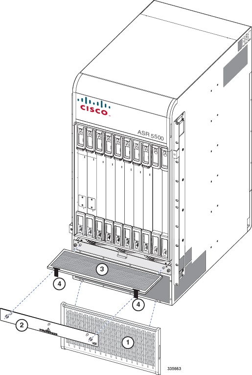
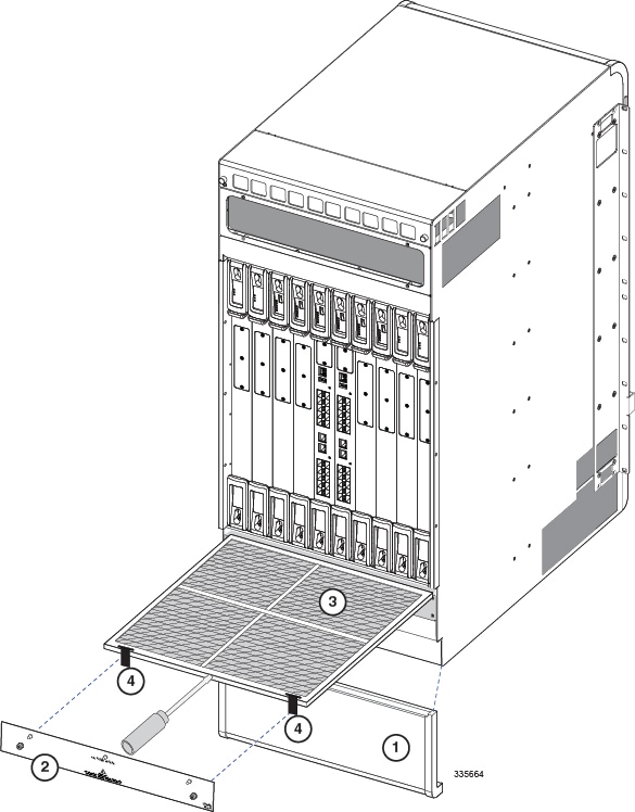
Rear Air Filter
Caution | Installing the air filter incorrectly may cause over-temperature conditions within the system. |
Fan Tray Units
The four fan tray units draw air up through the chassis for cooling and ventilation. The heated air exhausts through the vents at the rear and sides of the chassis.
This section describes how to remove and replace the front and rear fan tray units should there be a partial or complete failure of a unit.
Caution | Do not operate the chassis for more than a very brief period of time (less than one minute) with one or more fan trays out of service. Doing so may cause the system to overheat and result in component damage. |
Each front fan tray is controlled by its corresponding rear fan tray. Removal or failure of a rear fan tray will cause the corresponding front fan tray to cease running.
- Determining Whether a Fan Tray Unit Needs Replacing
- Replacing Front Fan Trays
- Replacing Rear Fan Trays
Determining Whether a Fan Tray Unit Needs Replacing
The system has several ways to indicate a fan tray failure. The first indicator is that the System Status LED on the System Status Card (SSC) illuminates red to indicate the failure of a chassis component.
If you see a red System Status LED on the SSC, you can determine whether it is a fan tray failure by using the CLI. Refer to Temperature and Fan Alarm Commands and show temperature Command.
Replacing Front Fan Trays
Caution | Fan tray units contain multiple fans that spin at a high rate of speed when the system is powered on. If the system is powered on when a fan tray is removed, do not touch moving fans. To minimize the risk of personal injury and potential equipment damage, pull the fan tray towards you until the fan tray extends out of the chassis approximately two inches (5 cm). Wait a few seconds to allow fans to spin down before fully removing the fan tray. |
Have the replacement fan tray available and ready to be installed before starting the replacement procedure.
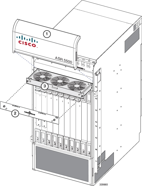
Replace the Upper Fan Tray
| Step 1 | At the front of the chassis, remove the cover panel from the top of the chassis. Firmly grasp the side edges of the panel and pull up and away to unsnap the panel. Put the panel safely aside. See figure below. | ||||||||
| Step 2 | Loosen the screws and remove the upper fan tray access panel from the chassis. Place it safely aside. | ||||||||
| Step 3 | Loosen the two screws that secure the fan tray to the chassis. | ||||||||
| Step 4 | Grasp the center pull and pull the failed fan tray unit from the chassis. | ||||||||
| Step 5 | Set the failed fan tray safely aside. | ||||||||
| Step 6 | Hold the front of the replacement fan tray by its sides and align it with the upper fan tray bay of the chassis. | ||||||||
| Step 7 | Slowly slide the fan tray into the chassis along the guides until the rear connector is firmly seated in the midplane. If the ASR 5500 is powered up, the fans should begin spinning. | ||||||||
| Step 8 | Tighten the screws that secure the fan tray to the chassis. | ||||||||
| Step 9 | Reinstall the access panel. | ||||||||
| Step 10 | Reinstall the top cover panel by aligning it over the balled posts and snapping it in place. | ||||||||
| Step 11 | For additional
instructions, refer to
Returning Failed Components.
| ||||||||
Replace the Lower Fan Tray
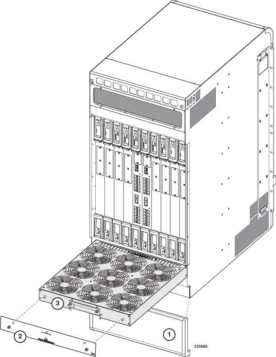
| Step 1 | Remove the cover panel from the bottom of the chassis. Firmly grasp the side edges of the panel and pull up and away to unsnap the panel. Put the panel safely aside. |
| Step 2 | Loosen the screws and remove the fan tray access panel from the chassis. Place it safely aside. |
| Step 3 | Use a #1 Phillips screwdriver to loosen the two screws that secure the handle to the front of the fan tray. |
| Step 4 | Flip up and grasp the fan tray handle and pull. Support the bottom of the fan tray unit with one hand as you pull it away from the chassis. |
| Step 5 | Place the failed fan tray unit safely aside. |
| Step 6 | Align the replacement fan tray within the lower chassis opening. With the unit resting on the bottom rail of the opening, push inward until it is firmly seated in the rear connectors. If the ASR 5500 is powered up, the fans should begin spinning. |
| Step 7 | Reinstall the access panel. |
| Step 8 | Reinstall the bottom cover panel by aligning it over the balled posts and snapping it in place. |
| Step 9 | For additional instructions, refer to Returning Failed Components. |
Replacing Rear Fan Trays
Caution | Fan tray units contain multiple fans that spin at a high rate of speed when the system is powered on. If the system is powered on when a fan tray is removed, do not touch moving fans. To minimize the risk of personal injury and potential equipment damage, pull the fan tray towards you until the fan tray extends out of the chassis approximately two inches (5 cm). Wait a few seconds to allow fans to spin down before fully removing the fan tray. |
Removing a rear fan tray will cause its companion front fan tray to power down. The front fan tray will power back up when the rear tray is replaced.
Have the replacement fan tray available and ready to be installed before starting the replacement procedure.
Replace the Upper Fan Tray
| Step 1 | At the rear of the chassis, remove the cover panel below the vent panel at the top of the chassis. Firmly grasp the side edges of the panel and pull up and away to unsnap the panel. Put the panel safely aside. |
| Step 2 | Loosen the knurled screws and remove the upper fan tray access panel from the chassis. Place it safely aside. |
| Step 3 | Use a #1 Phillips screwdriver to loosen the two screws that secure the fan tray to the chassis. |
| Step 4 | Grasp screw posts on the ends of the unit and pull the failed fan tray unit from the chassis. |
| Step 5 | Place the failed fan tray unit safely aside. |
| Step 6 | Align the replacement fan tray within the upper chassis opening. With the unit resting on the bottom rail of the opening, push inward until the rear connector is firmly seated in the midplane. If the ASR 5500 is powered up, the fans should begin spinning. |
| Step 7 | Tighten the screws that secure the fan tray to the chassis. |
| Step 8 | Reinstall the access panel. |
| Step 9 | Reinstall the top cover panel by aligning it over the balled posts and snapping it in place. |
| Step 10 | For additional instructions, refer to Returning Failed Components. |
Replace the Lower Fan Tray
If your chassis is equipped with a cable management tray, the tray must in the up and latched position to remove the lower fan tray. Refer to Raising the Cable Management Tray section in the Cable Management System Installation appendix.
| Step 1 | Remove the cover panel from the bottom of the chassis. Firmly grasp the side edges of the panel and pull up and away to unsnap the panel. Put the panel safely aside. See the figure below. | ||||||||
| Step 2 | Loosen the screws and remove the fan tray access panel from the chassis. Place it safely aside. | ||||||||
| Step 3 | Use a #1 Phillips screwdriver to loosen the two knurled screws that secure the handle to the front of the fan tray. | ||||||||
| Step 4 | Flip up and grasp the fan tray handle and pull. Support the bottom of the fan tray unit with one hand as you pull it away from the chassis. | ||||||||
| Step 5 | Place the failed fan tray unit safely aside. | ||||||||
| Step 6 | Align the replacement fan tray within the lower chassis opening. With the unit resting on the bottom rail of the opening, push inward until the rear connector is firmly seated in the midplane. If the ASR 5500 is powered up, the fans should begin spinning. | ||||||||
| Step 7 | Tighten the screws that secure the fan tray to the chassis. | ||||||||
| Step 8 | Reinstall the access panel. | ||||||||
| Step 9 | Reinstall the bottom cover panel by aligning it over the balled posts and snapping it in place. | ||||||||
| Step 10 | For additional
instructions, refer to
Returning Failed Components.
| ||||||||
PFU
Caution | Although a single PFU can provide power for a fully loaded chassis, it is strongly recommended that two fully functional PFUs always be installed for load-balancing and redundancy. |
Determining that a PFU has Failed
Run the show power command from the CLI.
Verify that all circuit breakers are in the ON position. The four blue LEDs should be ON.
Verify that the RTN and -48VDC lugs are securely attached to all posts at the upper rear of the chassis.
Verify that the ground lugs are securely attached to the posts on the bottom rear of the chassis.
Use a voltmeter to verify that the power distribution panel is supplying the correct voltage and sufficient current to the terminals at the rear of the PFU.
Check the cables from the power source to the rack for continuity.
If all of the above checks fail to isolate a fault, you may assume that the PFU has failed.
Replacing a PFU
| Step 1 | At the upper front of the chassis, unsnap and remove the cover over the front of the PFUs. See figure below. | ||||
| Step 2 | Power down the failed PFU by setting the four circuit breakers at the front of the PFU to OFF (O). | ||||
| Step 3 | At the power distribution panel, turn OFF the four power feeds going to the failed PFU. | ||||
| Step 4 | Remove all the
power feed cables from the terminals at the rear of the PFU.
Important:
All cables going to the PFU should be labeled with the PFU terminal number and power distribution panel circuit number. | ||||
| Step 5 | From the front of the chassis, use a Phillips #2 screwdriver to loosen the four screws securing the failed PFU to the chassis. | ||||
| Step 6 | Grasp the handle on the front of the PFU and pull forcefully downward to extract the PFU from the power plane connectors. Pull the unit from the chassis and set it aside. | ||||
| Step 7 | Verify that the four circuit breakers on the front of the replacement PFU are in the OFF (O) position. the handle on the front of the PFU should be in the down position. | ||||
| Step 8 | Slide the replacement PFU into the PFU bay until it is flush against the rear connectors. Firmly push the PFU into the power plane connectors. Pull the handle forcefully upwards to fully seat the PFU into the power plane connectors. | ||||
| Step 9 | Use a Phillips #2 screwdriver to tighten each of the four screws on the PFU to secure it to the chassis. | ||||
| Step 10 | At the rear of
the chassis replace the power feed cables on the PFU input terminals.
| ||||
| Step 11 | Turn ON the four power feeds from the power distribution panel to the PFU. | ||||
| Step 12 | At the front of the chassis, power up the PFU by setting the four circuit breakers on its front panel to ON ( | ). The four blue LEDs should be ON. | ||||
| Step 13 | Reinstall the
plastic terminal cover on the top-rear of the chassis.
| ||||
| Step 14 | Reinstall the front top cover panel by aligning it over the balled posts and snapping it in place. | ||||
| Step 15 | For additional
instructions, refer to
Returning Failed Components.
|
Circuit Cards
This section describes how to replace circuit cards in the ASR 5500 chassis.
- Determining Whether a Card has Failed
- Replacing Universal Cards
- Backing Up the System Configuration
- Synchronize File System
- Preparing a Card for Replacement
- Replacing a Failed Card
- Cleaning Fiber Optic Connectors
Determining Whether a Card has Failed
The ASR 5500 has several ways to indicate an application card failure. The first indicator is that the Status LED on the System Status Card (SSC) turns red to indicate the failure of a chassis component. Another indicator is the Run/Fail LED on an application card is red or turns off if that card has a problem.
If you see either of these indicators, you can determine the nature of the problem by using the CLI or checking the Simple Network Management Protocol (SNMP) traps that may have been generated.
show card diag Command
Execute the show card diag slot_# command from the CLI in Exec mode. slot_# is the chassis slot number in which the particular card that you wish to monitor is installed. The following is a sample output for this command to monitor the card in chassis slot 5:
[local]asr5500# show card diag 5

Card 5:
Counters:
        Successful Warm Boots : 0
            (last at Friday July 29 13:45:58 us-eastern 2011)
        Successful Cold Boots : 2
            (last at Friday July 29 13:46:20 us-eastern 2011)
        Total Boot Attempts      : 1
        In Service Date          : Fri Jul 29 13:50:58 2011
    Status:
        IDEEPROM Magic Number : Good
        Boot Mode                : Normal
        Card Diagnostics         : Pass
        Current Failure          : None
        Last Failure             : None
        Card Usable              : Yes
    Current Environment:
        Temp: DDR-C0D0           : 30.00 C (limit 100.00 C)
        Temp: DDR-C0D1           : 30.00 C (limit 100.00 C)
        Temp: DDR-C1D0           : 30.00 C (limit 100.00 C)
        Temp: DDR-C1D1           : 30.00 C (limit 100.00 C)
        Temp: DDR-C2D0           : 30.00 C (limit 100.00 C)
        Temp: DDR-C2D1           : 30.00 C (limit 100.00 C)
        Temp: CPU-N0C0           : 30.00 C (limit 101.00 C)
        Temp: CPU-N0C1           : 30.00 C (limit 101.00 C)
        Temp: CPU-N0C2           : 30.00 C (limit 101.00 C)
        Temp: CPU-N0C3           : 30.00 C (limit 101.00 C)
        Temp: CPU-N0C4           : 30.00 C (limit 101.00 C)
        Temp: CPU-N0C5           : 30.00 C (limit 101.00 C)
        Temp: IOH                : 35.00 C (limit 110.00 C)
        Temp: NP4 #0             : 35.00 C (limit 115.00 C)
        Temp: NP4 #1             : 35.00 C (limit 115.00 C)
        Temp: NP4 #2             : 35.00 C (limit 115.00 C)
        Temp: NP4 #3             : 35.00 C (limit 115.00 C)
        Temp: LM94               : 0.00 C
        Temp: Petra1             : 35.00 C (limit 100.00 C)
        Temp: Petra2             : 35.00 C (limit 100.00 C)
        Temp: Upper-right        : 27.50 C (limit 85.00 C)
        Temp: Petra3             : 35.00 C (limit 100.00 C)
        Temp: Petra4             : 35.00 C (limit 100.00 C)
        Temp: Mid-right          : 27.50 C (limit 85.00 C)
        Temp: MDF                : 25.00 C (limit 80.00 C)
        Temp: Lower-right        : 22.50 C (limit 75.00 C)
        Temp: Upper-left         : 27.50 C (limit 85.00 C)
        Temp: Lower-left         : 27.50 C (limit 85.00 C)
        Temp: DC1                : 27.50 C (limit 85.00 C)
        Temp: DC2                : 27.50 C (limit 85.00 C)
        Temp: F600 #1            : 0.00 C
        Temp: F600 #2            : 0.00 C
        Voltage: 12V-A           : 0.000 V
        Voltage: CPU0 VTT        : 1.136 V (min 0.992 V, max 1.281 V)
        Voltage: 12V-B           : 0.000 V
        Voltage: 12V-C           : 0.000 V
        Voltage: 1.8V            : 1.800 V (min 1.700 V, max 1.900 V)
        Voltage: 1.5V            : 1.505 V (min 1.430 V, max 1.580 V)
        Voltage: CPU0 VCC        : 1.064 V (min 0.712 V, max 1.417 V)
        Voltage: 1.2V            : 1.200 V (min 1.140 V, max 1.260 V)
        Voltage: 3.3V            : 3.305 V (min 3.140 V, max 3.470 V)
        Voltage: 5V              : 5.000 V (min 4.750 V, max 5.250 V)
        Voltage: 3.0V Batt       : 0.000 V
        Voltage: 2.5V            : 2.505 V (min 2.380 V, max 2.630 V)
        Voltage: 1.53V DDR0      : 1.444 V (min 1.282 V, max 1.606 V)
        Voltage: 7.5V            : 7.505 V (min 7.130 V, max 7.880 V)
        Voltage: 1.1V IOH        : 1.099 V (min 1.045 V, max 1.155 V)
        Voltage: 3.3V Stdby      : 3.300 V (min 2.970 V, max 3.630 V)
        Voltage: 48V-A           : 0.000 V
        Voltage: 48V-B           : 0.000 V
        Current: 48V-A           : 0.00 A
        Current: 48V-B           : 0.00 A
        Airflow: Lower Left      : 0 FPM
        Airflow: Lower Middle    : 0 FPM
SNMP Traps
The ASR 5500 supports SNMP traps that are triggered when conditions indicate status changes on application cards.
To display SNMP trap statistics, run the show snmp trap statistics command. A sample output appears below.
[local]asr5500# show snmp trap statistics
SNMP Notification Statistics:
    Total number of notifications      : 13
    Last notification sent             : Friday July 29 13:46:38 us-eastern 2011
    Notification sending is            : enabled
    Notifications have never been disabled
    Notifications have never been cleared
    Notifications in current period    : 0
    Notifications in previous period   : 0
    Notification monitor period        : 300 seconds

Trap Name                           #Gen  #Disc  Disable Last Generated
----------------------------------- ----- -----  ------- --------------------
CardUp                                 4      0        0  2011:07:29:13:46:35
PortLinkDow                            2      0        0  2011:07:29:13:46:38
CLISessStart                           1      0        0  2011:07:29:13:46:37
CardActive                             1      0        0  2011:07:29:13:46:20
CardStandby                            3      0        0  2011:07:29:13:46:35
PortDown                               2      0        0  2011:07:29:13:46:38

Total number of notifications Disabled : 0
Run the show snmp trap history command to view recently sent SNMP traps.
Replacing Universal Cards
UMIO cards, UDPCs and UDPC2s are functional replacements for MIOs, DPCs and DPC2s. However, special chassis and card licenses may be required in order for the UMIO, UDPC or UDPC2 to operate. For additional information, refer to Chassis Universal License Requirements.
Data processing cards must all be of the same type – DPC, UDPC, DPC2 or UDPC2 – in a chassis.
Backing Up the System Configuration
Prior to replacing a failed card of any type, it is good practice to save the current configuration to an external USB device or remote network location.
Refer to Verifying and Saving Your Configuration in the System Administration Guide for detailed instructions
Preparing a Card for Replacement
- MIO/UMIO – If the active MIO/UMIO fails, a switchover to the standby MIO/UMIO is automatic. In the event that an issue arises that is not severe enough for the system to perform an automatic switchover, a manual switchover can be invoked by executing the Exec mode card switch from <5 or 6> to <6 or 5> command.
- DPC/UDPC and DPC2/UDPC2 – An Exec mode card busy-out slot_number command moves processes from the source DPC/UDPC to the destination DPC/UDPC, or disables the DPC/UDPC from accepting any new calls. When busy-out is enabled, the DPC/UDPC stops receiving new calls but continues to process calls until they are completed. The busy-out procedure is completed in background.
- DPC/UDPC and DPC2/UDPC2 – In the event of the critical failure of a DPCx/UDPCx, tasks will be automatically be migrated from the active card to a redundant card in standby mode. In the event that an issue arises that is not severe enough for the system to perform an automatic migration, a manual migration can be initiated using the Exec mode card migration from original_slot# to final_slot#
- FSC – The FSCs are configured for n+1 redundancy. When an active FSC fails, an automatic switchover is made to the standby FSC. At least one FSC must be in standby mode prior to initiating a switchover. In the event that an issue arises that is not severe enough for the system to perform an automatic switchover, a manual switchover can be invoked by executing the Exec mode card switch from slot_number to slot_number command.
An FSC-200GB (equipped with two 200GB SSDs) can be replaced with an FSC-400GB (equipped with a single 400GB SSD) only if the StarOS release supports the non-RAID 0 configuration of the FSC-400GB.
Cards other than MIO/UMIO that are in either the Active or Standby modes should be halted prior to removal. Halting these cards places them into the "offline" mode. In this mode, the card is unusable for session processing as either an active or redundant component. If a card in the active mode is halted, its tasks, processes, or network connections will be migrated or switched to a redundant component prior to entering the offline mode.
Initiate a manual card migration by entering the Exec mode card halt slot# command.
Verify that the migration was successful by entering the Exec mode show card table command. Check the entry in the Oper State column next to the card that was just halted. Its state should be Offline. If the card was in active mode prior to the execution of this command, the state of the redundant component associated with it should now be Active.
All status LEDs on the halted card should be OFF when a card is offline and ready to be replaced.
Caution | Attempting to replace a circuit card that has not been taken offline may result in spurious error messages and unexpected behavior that may initiate reload of other cards. |
For additional information about the above commands and procedures, refer to the Command Line Interface Reference and the Troubleshooting section of the System Administration Guide.
Replacing a Failed Card
This section describes how to remove and replace a failed circuit card.
Circuit cards can be replaced while the ASR 5500 is operating.
The optical SFP+ interfaces on the MIO/UMIO comply with the limits for Class 1 laser devices for IEC825, EN60825, and 21CFR1040 specifications.
If the chassis in which the card is to be replaced interfaces via SRP with a peer chassis for Interchassis System Recovery (ICSR), the chassis to receive the replacement card must be placed in SRP Standby. Verify its current state by running the Exec mode show srp info command. Refer to the System Administration Guide for instructions.
Caution | During installation, maintenance, and/or removal, wear a grounding wrist strap connected to the ASR 5500 chassis to avoid ESD damage to the components. Failure to do so could result in damage to sensitive electronic components and potentially void your warranty. |
- Remove I/O Connections (MIO/UMIO and SSC)
- Remove and Replace the Circuit Card
- Swapping the SDHC Memory Card
Remove I/O Connections (MIO/UMIO and SSC)
MIO or UMIO
If your ASR 5500 chassis is equipped with a cable management system, refer to the special instructions for Detaching Network Cables from the Card Bracket in the Cable Management System Installation appendix.
| Step 1 | Unplug the cable connected to the RJ45 serial Console port. |
| Step 2 | Unplug any cables connected to the RJ45, 1 GbE ports. |
| Step 3 | If necessary, remove a USB memory stick from the USB port. |
| Step 4 | Remove the fiber optic
cables connected to 10 GbE ports on the daughter card(s). Install
dust caps on the ends of the fiber optic cables. Important:
Do not remove the transceivers from MIO/UMIO ports. Replacement MIO/UMIO cards are shipped with replacement transceivers already installed. |
Remove and Replace the Circuit Card
Caution | Do not leave chassis slots uncovered for extended periods of time (more than a few minutes). This reduces air flow through the chassis and could cause overheating. Make sure a card or baffle is installed in every unpopulated chassis slot at all times. |
If your ASR 5500 chassis is equipped with a cable management system, refer to the special instructions for Lowering the Cable Management Tray in the Cable Management System Installation appendix.
Caution | All status LEDs on the failed card should be OFF prior to removing the card from the chassis. See Preparing a Card for Replacement. |
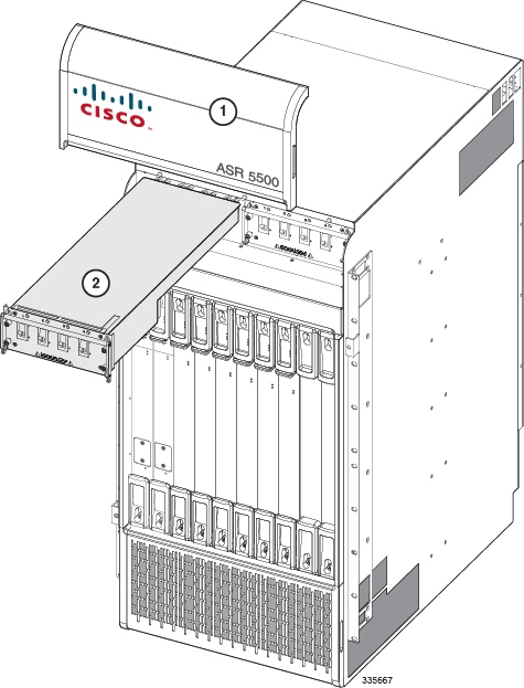
| Step 1 | Use a Phillips #2 screwdriver to loosen the captive screws within the top and bottom handles of the failed card. See figure below. | ||||||||
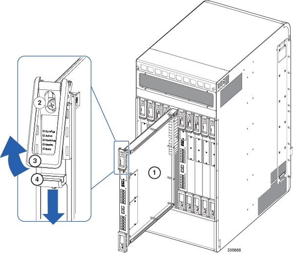
| Step 2 | Slide the blue subhandle underneath the top handle downward to unlock the handle and disable the card interlock switch. | ||||||||
| Step 3 | Simultaneously pull both card handles firmly outward until the card is unseated from the midplane connectors. | ||||||||
| Step 4 | Firmly grasp the top and bottom edges of the card and pull the card slowly out of the chassis. Set the failed card safely aside. | ||||||||
| Step 5 | If an MIO/UMIO is being replaced, refer to Swapping the SDHC Memory Card. and swap the SDHC memory card from the failed MIO/UMIO into the replacement MIO/UMIO. | ||||||||
| Step 6 | Flip the top and bottom handles of the replacement card fully outwards. | ||||||||
| Step 7 | Holding the card by the top and bottom edges of the front panel, align the card with the upper and lower card guides of the chassis slot. Gently slide the card into the slot until the handles touch the card cage rails. | ||||||||
| Step 8 | Simultaneously push the top and bottom handles firmly inward until the card is fully seated in the midplane connectors. Press firmly on the card's faceplate to ensure that it is fully seated. The front panel should be flush against the chassis upper and lower card mounts for the slot. | ||||||||
| Step 9 | Slide the blue subhandle under the top handle to lock the handle in place and enable the interlock switch. | ||||||||
| Step 10 | Use a Phillips #2 screwdriver to tighten the captive screws within the top and bottom handles of the card. | ||||||||
| Step 11 | For each MIO/UMIO daughter card, firmly press the SFP+ transceivers inwards and reconnect the fiber optic cables. | ||||||||
| Step 12 | Reconnect any
other I/O cables that may have been removed from the failed card.
Important:
Connectors on the fiber optic cables must be free of dust, oil, or other contaminants. Before connecting the cable to the transceiver, carefully clean the connectors as described in Cleaning Fiber Optic Connectors. Important:
If your ASR 5500 chassis is equipped with a cable management system, refer to the special instructions for Reconnecting Network Cables to the Card Bracket and Raising the Cable Management Tray in the Cable Management System Installation appendix. | ||||||||
| Step 13 | A circuit card will automatically initiate a Power On Self Test (POST) upon insertion into the backplane. If the POST is successfully completed, the card will reload (reboot) itself. Refer to the Verifying System Startup section in the System Power-up chapter for additional information. | ||||||||
| Step 14 | From the CLI run the Exec mode filesystem synchronize all command. | ||||||||
| Step 15 | Back up the system configuration. Refer to Backing Up the System Configuration. | ||||||||
| Step 16 | For additional
instructions, refer to
Returning Failed Components.
|
Swapping the SDHC Memory Card
The SDHC memory card on the MIO/UMIO appears as the /flash drive on the CLI. The /flash drive stores configuration data, including the boot priority settings.
Caution | Removal and replacement of the SDHC card must be performed at an ESD-safe workstation. Observe ESD precautions when handling the SDHC card and MIO/UMIO cards. |
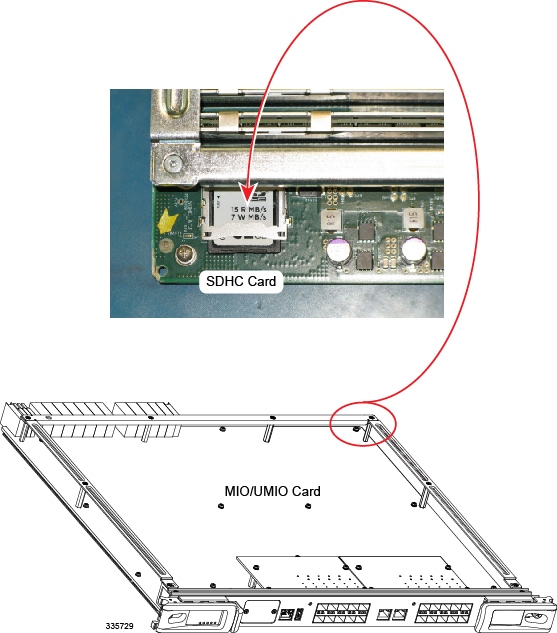
| Step 1 | On a failed MIO/UMIO, locate the SDHC card in the bottom rear corner of the circuit card (see figure below). |
| Step 2 | The SDHC card resides in a push-push type holder. With your finger tip, push the rear edge of the SDHC card inward until you hear a click. Release your finger and the card will pop out of the holder. Remove the card and store it safely aside. |
| Step 3 | On the replacement MIO/UMIO, locate the SDHC card holder and remove the SDHC card. That card contains only a basic configuration for testing purposes; insert it into the failed card prior to returning the circuit card to Cisco. |
| Step 4 | On the replacement MIO/UMIO, insert the SDHC card removed from the failed MIO/UMIO. With your finger tip, push the SDHC card inward until you hear a click and release your finger. This completes the SDHC card swap out procedure. |
Cleaning Fiber Optic Connectors
Fiber optic connectors join optical fibers together. They can be damaged by improper cleaning and connection procedures. Dirty or damaged fiber optic connectors can degrade communication.
In a fiber optic system, light is transmitted through extremely small fiber cores. Because fiber cores are often 62.5 microns or less in diameter, and dust particles range from a tenth of a micron to several microns in diameter, dust and any other contamination at the end of the fiber core can degrade the performance of the connector interface where the cores meet. Therefore, the connector must be precisely aligned and the connector interface must be absolutely free of foreign material.
Connector loss, or insertion loss, is a critical performance characteristic of a fiber optic connector. Return loss is also an important factor. Return loss specifies the amount of reflected light: the lower the reflection, the better the connection. The best physical contact connectors have return losses of better than –40 dB, but –20 to –30 dB is more common.
The connection quality depends on two factors: the type of connector and the proper cleaning and connection techniques. Dirty fiber connectors are a common source of light loss. Keep the connectors clean at all times, and keep the dust plugs or covers installed when the connectors are not in use.
As a general rule, any time you detect a significant, unexplained loss of light, clean the connectors. To clean the optical connectors, obtain and use a fiber optic cleaning kit and follow the manufacturer's usage instructions. Clean the ferrule, the protective tube or cone that surrounds the fiber core, and the end-face surface of the fiber core.
- Use a lint-free tissue soaked in 99 percent pure isopropyl alcohol and gently wipe the end-face of the fiber core. Wait for five seconds for the surfaces to dry and wipe the surfaces a second time.
- Use clean, dry, oil-free compressed air to remove any residual dust from the connector.
- Use a magnifying glass or inspection microscope to inspect the ferrule at angle. Do not look directly into the aperture. If you detect any contamination, repeat Steps 1 and 2.
Caution | Because invisible laser radiation may be emitted from the aperture of the port when no cable is connected, avoid exposure to laser radiation and do not stare into open apertures. |
Returning Failed Components
If the failed component is still under Cisco warranty or a hardware maintenance contract, return it for repair or replacement.
If the failed component is out of warranty or not covered by a maintenance contract, contact Cisco to determine if it can be sent in for repair at an additional cost.
Please contact your local Cisco sales or service representative for additional information.
Caution | Use a saved shipping carton and anti-static bag when returning a circuit card to Cisco for fault analysis. Failure to use the proper packaging will make it impossible to isolate problems resulting from physical or ESD damage during shipping. For additional information see the RMA Shipping Procedures appendix. |
SFP+ transceivers must be returned along with MIO/UMIO cards. Leave the fiber optic devices installed in the card.
Disposal of this product should be performed in accordance with all national laws and regulations.