Contents
- MIO Port Cabling
- Interface Ports
- Front Panel Ports
- Daughter Card Ports
- Port Status LEDs
- Cable Management System
- Console Port
- RJ45 Port Pinouts
- RJ45 to DB9 Adapter
- USB to DB9 Adapter
- Connect Console Port to Workstation
- Connect Console Port to Terminal Server
- Ethernet Management STP Ports
- RJ45 Port Pinouts
- Connect 1000Base-T Interface to Network Device
- 10 GbE Optical Daughter Card Ports
- Fiber Optic Bend Radius Guidelines
- Recommended Bend Radius
- Bend-Insensitive Multimode Fiber
- Fiber Optical Connections
- Removing Dust Plugs
- Connecting Fiber Optic Cables
- Cleaning Fiber Optic Connectors
MIO Port Cabling
- Interface Ports
- Port Status LEDs
- Cable Management System
- Console Port
- Ethernet Management STP Ports
- 10 GbE Optical Daughter Card Ports
- Fiber Optic Bend Radius Guidelines
- Fiber Optical Connections
Interface Ports
The interface ports are selectively enabled based on their functions in the system – management versus non-management.
Front Panel Ports
one serial Console port (RJ45)
two 1 Gigabit Ethernet ports (RJ45)
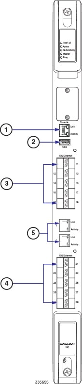
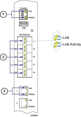
Port Status LEDs
Cable Management System
If you have equipped your ASR 5500 chassis and MIO/UMIO cards with the Cable Management System, refer to the Routing and Securing Network Cables section of the Cable Management System Installation appendix for additional information.
Console Port
The Console port (logical Port 3) is an RJ45 RS-232 interface on an MIO or UMIO card that provides access to the command line interface (CLI). The interface communicates at 9600 to 115200 bps; the default is 115,200 bps.
A connection to the Console port is required if you wish to view boot messages whenever the ASR 5500 chassis is powered up or rebooted. Only the Console port on the Master MIO or UMIO supports logs and CLI sessions. The Console port on the Standby MIO or UMIO is inactive.
- RJ45 Port Pinouts
- RJ45 to DB9 Adapter
- USB to DB9 Adapter
- Connect Console Port to Workstation
- Connect Console Port to Terminal Server
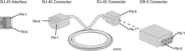
RJ45 Port Pinouts

RJ45 to DB9 Adapter
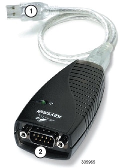
USB to DB9 Adapter
A USB to Serial DB9 adapter is supplied with each MIO/UMIO. The DB9 connector on the adapter is male and can be used in conjunction with the Console RJ45 Cable and DB9 Adapter to connect a laptop or workstation to the RJ45 port on the MIO/UMIO.
| DB9 Pin | Signal Description | Signal type | Console Port |
|---|---|---|---|
| 1 | Data Carrier Detect (DCD) | Input | Unused |
| 2 | Receive Data (RX) | Input | TX |
| 3 | Transmit Data (TX) | Output | RX |
| 4 | Data Terminal Ready (DTR) | Output | Unused |
| 5 | Signal Ground (SGND) | Ground | Ground |
| 6 | Data Set Ready (DSR) | Input | Unused |
| 7 | Request To Send (RTS) | Output | Unused |
| 8 | Clear To Send (CTS) | Input | Unused |
| 9 | Ring Indicator (RI) | Input | Unused |
This adapter provides a serial port on a laptop or workstation that does not have one. It draws power from the USB port.

Connect Console Port to Workstation
You can connect the Console port to a workstation or a laptop with a serial port running a communications application, such as Minicom for Linux® or HyperTerminal® for Windows.
To connect a workstation to the Console port, do the following:
| Step 1 | Plug one end of an RJ45 cable to the port labeled Console on the MIO or UMIO. |
| Step 2 | Plug the other end of the RJ45 cable into the DB9 adapter. |
| Step 3 | Connect the DB9 end of the adapter into the serial port on the workstation. |
| Step 4 | Configure the communications
application on the workstation to support the following:
|
Connect Console Port to Terminal Server
You can connect the terminal server to a serial port on a terminal server.
The Console port does not support flow control signaling required by some types of terminal servers. Flow control must be disabled on the connected equipment.
To connect a terminal server to the Console port, do the following:
| Step 1 | Plug one end of an RJ45 cable to the port labeled Console on the MIO or UMIO. |
| Step 2 | Plug the other end of the RJ45 cable into a port on the terminal server. |
| Step 3 | Configure the communications
protocol on the terminal server port to support the following:
Important:
For additional information on connecting the Console port to Cisco servers equipped with asynchronous interface modules, refer to the Console Port to Cisco Server Cabling appendix. |
Ethernet Management STP Ports
MIOs/UMIOs support two autosensing RJ45 10/100/1000Base-T (IEEE 802.3ab) Ethernet, shielded twisted-pair (STP) copper interfaces (logical Ports 1 and 2) for out-of-band system management access to the CLI.
To comply with GR-1089 intra-building, lightning-immunity requirements and FCC Radiated Emissions Criteria, you must use STP cable and ensure that it is properly terminated at both ends.
 Caution | The 1000Base-T management ports are suitable for connection to intra-building or unexposed wiring or cabling only. These intra-building ports MUST NOT be metallically connected to interfaces that connect to the outside plant (OSP) or its wiring. These interfaces are designed for use as intra-building interfaces only (Type 2 or Type 4 ports as described in GR-1089-CORE, Issue 5) and require isolation from the exposed OSP cabling. The addition of Primary Protectors is not sufficient protection in order to connect these interfaces metallically to OSP wiring. |
The ports support MDI and MDI-X connectors. Ethernet ports normally use MDI connectors and Ethernet ports on a hub normally use MDI-X connectors.
An Ethernet straight-through cable is used to connect an MDI to an MDI-X port. A cross-over cable is used to connect an MDI to an MDI port, or an MDI-X to an MDI-X port.
Connect 1000Base-T Interface to Network Device
To facilitate maintenance of the network cabling, the Cat-5 cables should be labeled with terminating destinations.
| Step 1 | Insert one end of the Cat-5 cable into the top MGMT connector (Port 1). |
| Step 2 | Attach the other end of the Cat-5 cable to the appropriate network interface. |
| Step 3 | Repeat Steps 1 and 2 to connect the bottom MGMT connector (Port 2). |
10 GbE Optical Daughter Card Ports
Caution | The 10 Gigabit Ethernet ports on the daughter cards are only certified to work with SFP+ transceivers tested and approved by Cisco. MIO and UMIO cards ship with SFP+ transceivers installed. |
10GBase-SR – connects the port to a multi-mode fiber optic cable over relatively short distances (30.80 meters).
10GBase-LR – connects the port to a single-mode fiber optic cable over a maximum distance of 10km.
The table below lists the signaling parameters supported for the above transceiver types.
| SFP+ Transceiver Type | Parameter | Value |
|---|---|---|
| 10GBase-SR | Maximum transmit level | -1.0dBm |
| Minimum transmit level | -7.3dBm | |
| Maximum receive level | -1.0 dBm (saturation average power) | |
| Minimum receive level | -11.1 (sensitivity average power) | |
| 10GBase-LR | Maximum transmit level | 0.5 dBm |
| Minimum transmit level | -8.2 dBm | |
| Maximum receive level | 0.5 dBm (saturation average power) | |
| Minimum receive level | -12.6 (sensitivity average power) |
Fiber Optic Bend Radius Guidelines
When a fiber cable is bent excessively, the optical signal within the cable may refract and escape through the fiber cladding. Bending can also permanently damage the fiber by causing micro cracks, especially during cable installation due to pulling forces. The result is known as bend loss: a loss of signal strength that may compromise the integrity of the data transmission.
Caution | To avoid damaging the fiber optic cable, the cable connector, or the optical interface, do not install or remove fiber optic transceivers with fiber-optic cables attached. Disconnect all cables before removing or installing a transceiver. |
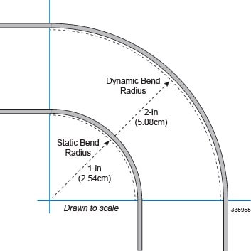
Recommended Bend Radius
- The dynamic bend radius is the tightest recommended bend while installing cable at the maximum rated tension. It is the larger of the two specified bend radii (see figure below). Throughout the pull, the minimum bend radius must be strictly followed. If a location exists in the middle of a run where a relatively tight bend is unavoidable, the cable should be hand-fed around the bend or a pulley can be used.
- The static bend radius is the tightest recommended bend while the cable is under a minimum tension. It is the smaller of the two specified bend radii. After the pull is complete, the cable can be bent more tightly to fit into existing space, but not to exceed the long term minimum bend radius.
Always follow the manufacturer's guidelines for minimum bend radius and tension. Failure to do so may result in high attenuation (macrobends) and possible damage to the cable and fiber. Guidelines are normally supplied with the cable manufacturer specification sheets. If the bend radius specifications are unknown, the recommendation is to maintain a minimum radius of 20 times the diameter of the cable.
Bend-Insensitive Multimode Fiber
An alternative for maintaining tighter than recommended bend radii is use of Bend-Insensitive Multimode Fiber (BIMMF). BIMMF is more impervious to bend loss than standard 50-micron multimode fiber (MMF) cable.
BIMMF cables are only optimized for 850nm wavelengths and not for 1300nm wavelengths.
BIMMF is structurally the same as standard MMF cable but there is an added layer of glass between the core and the cladding. This layer of glass has a much lower refractive index than the cladding.
Bend-insensitive 50-micron MMF cable is full backwards compatible with existing 50-micron MMF and fully compliant with OM2, OM3 and OM4 standards.
Fiber Optical Connections
Removing Dust Plugs
-
Always keep the protective dust plugs on the unplugged fiber-optic cable connectors and the transceiver optical bores until you are ready to make a connection.
-
Always inspect and clean the LC connector end-faces just before making any connections. See Cleaning Fiber Optic Connectors.
-
Always grasp the LC connector housing to plug or unplug a fiber-optic cable.
To facilitate maintenance of the network cabling, all fiber optic cables should be labeled with terminating destinations.
Connecting Fiber Optic Cables
| Step 1 | Remove the dust plug from the network interface LC connector of the SFP+ module. Save the dust plug for future use. |
| Step 2 | Inspect and clean the LC connector's fiber-optic end-faces. |
| Step 3 | Insert the duplex LC/PC connector on the network cable into the duplex port on the module. |
| Step 4 | Attach the other end of the network fiber-optic cable to the network device that you want to connect. |
| Step 5 | Repeat Step 1 through Step 4 for the remaining ports on the daughter card. |
| Step 6 | Repeat Step 1 through Step 4 for ports on the second DC. |
Cleaning Fiber Optic Connectors
Fiber optic connectors join optical fibers together. They can be damaged by improper cleaning and connection procedures. Dirty or damaged fiber optic connectors can degrade communication.
In a fiber optic system, light is transmitted through extremely small fiber cores. Because fiber cores are often 62.5 microns or less in diameter, and dust particles range from a tenth of a micron to several microns in diameter, dust and any other contamination at the end of the fiber core can degrade the performance of the connector interface where the cores meet. Therefore, the connector must be precisely aligned and the connector interface must be absolutely free of foreign material.
Connector loss, or insertion loss, is a critical performance characteristic of a fiber optic connector. Return loss is also an important factor. Return loss specifies the amount of reflected light: the lower the reflection, the better the connection. The best physical contact connectors have return losses of better than –40 dB, but –20 to –30 dB is more common.
The connection quality depends on two factors: the type of connector and the proper cleaning and connection techniques. Dirty fiber connectors are a common source of light loss. Keep the connectors clean at all times, and keep the dust plugs or covers installed when the connectors are not in use.
As a general rule, any time you detect a significant, unexplained loss of light, clean the connectors. To clean the optical connectors, obtain and use a fiber optic cleaning kit and follow the manufacturer's usage instructions. Clean the ferrule, the protective tube or cone that surrounds the fiber core, and the end-face surface of the fiber core.
- Use a lint-free tissue soaked in 99 percent pure isopropyl alcohol and gently wipe the end-face of the fiber core. Wait for five seconds for the surfaces to dry and wipe the surfaces a second time.
- Use clean, dry, oil-free compressed air to remove any residual dust from the connector.
- Use a magnifying glass or inspection microscope to inspect the ferrule at angle. Do not look directly into the aperture. If you detect any contamination, repeat Steps 1 and 2.
Caution | Because invisible laser radiation may be emitted from the aperture of the port when no cable is connected, avoid exposure to laser radiation and do not stare into open apertures. |