Contents
Power
Cabling
Power Considerations
Each chassis supports up to eight -48 VDC, 80-amp power feeds, four per PFU. Each feed consists of a supply and return cable.
The power source must be a UL/CSA listed device with a regulated output no greater than -60VDC.
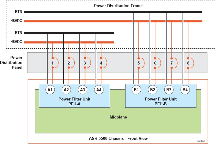
Typically, the DC power feeds are fed from a power distribution frame (PDF) to a power distribution panel (PDP) at the rack.
The DC power Battery Return (BR) or positive terminal, must be grounded at the source end (power feed or mains power end).
Minimum 4 AWG multiple strand, high-flex cable is recommended for final connections from the PDP to the PFUs. Although the chassis configuration may not draw maximum power, it should be sized and wired to handle 12.8 kW of power to accommodate future expansion. See Power Cable Requirements.
Each feed connects to supply and return terminals on the rear of the PFUs using two-hole lugs crimped to the end of each cable. The feed cables are routed through openings in each side of the chassis. The input terminals are wired through EMI filters to the ASR 5500 backplane.
For a non-redundant chassis power configuration, live power feeds must be connected to all four power inputs on PFU-A. For a redundant power configuration, live power feeds must be connected to all four power inputs on PFU-B. The four power feeds per PFU assure that all power planes in the backplane are energized; power is available to all card slots in the chassis. For additional information, see Internal Power Planes.
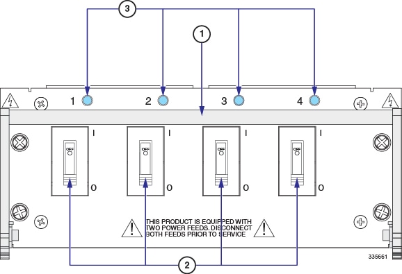
The circuit breakers at the power distribution panel must disconnect the supply line of each -48VDC feed. However, it is recommended that the circuit breakers at the power distribution panel simultaneously disconnect both poles (supply and return) for each -48 VDC feed to completely isolate the ASR 5500 from the power source.
To maintain power redundancy, separate –48 VDC supply circuits should be used to feed each DC power input on both PFUs.
 Caution | Set the circuit breakers on the distribution panel to the OFF position before making the power connections at the PFUs. |
Each power input cable must be terminated with a supplied Panduit LCD4-14AF-L 2-hole, 90-degree lug using the appropriate crimping tool and die.
If a DC power input should fail, the operating supply circuits continue to power the ASR 5500.
Internal Power Planes
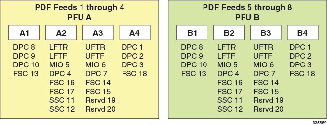
Four inputs are labeled A1 through A4 and the other inputs are labeled B1 through B4. A1 is redundant for B1 and so on. The inputs correspond to the four power planes that supply power to various chassis components as shown in the table and figure below.
The SSC monitors all eight feeds for outages.
All four power inputs on a PFU must be connected to live power feeds to assure that all card slots in the ASR 5500 chassis are energized.
Chassis Power Card Slot Allocations
| Card Type | Slot | Plane 1 | Plane 2 | Plane 3 | Plane 4 |
|---|---|---|---|---|---|
| Rear Cards | |||||
| DPC or UDPC, DPC2 | 1 | — | — | — | Yes |
| DPC or UDPC, DPC2 or UDPC2 | 2 | — | — | — | Yes |
| DPC or UDPC, DPC2 or UDPC2 | 3 | — | — | — | Yes |
| DPC or UDPC, DPC2 or UDPC2 | 4 | — | Yes | — | — |
| MIO or UMIO | 5 | — | Yes | — | — |
| MIO or UMIO | 6 | — | — | Yes | — |
| DPC or UDPC, DPC2 or UDPC2 | 7 | — | — | Yes | — |
| DPC or UDPC, DPC2 or UDPC2 | 8 | Yes | — | — | — |
| DPC or UDPC, DPC2 or UDPC2 | 9 | Yes | — | — | — |
| DPC or UDPC, DPC2 or UDPC2 | 10 | Yes | — | — | — |
| Front Cards | |||||
| SSC | 11 | — | Yes | — | — |
| SSC | 12 | — | Yes | — | — |
| FSC | 13 | Yes | — | — | — |
| FSC | 14 | — | — | Yes | — |
| FSC | 15 | — | — | Yes | — |
| FSC | 16 | — | Yes | — | — |
| FSC | 17 | — | Yes | — | — |
| FSC | 18 | — | — | — | Yes |
| Reserved | 19 | — | — | Yes | — |
| Reserved | 20 | — | — | Yes | — |
| Fan Trays | |||||
| Upper | Top | — | — | Yes | — |
| Lower | Bottom | — | Yes | — | — |
Power Feed Connections
Power Cable Requirements
Sizing Power Cables
Each conductor between the PDF and PDP should be calculated assuming a 0.3 volt drop from the PDF to the panel.
Each cable between the PDP and ASR 5500 PFUs should be calculated a 0.3 volt drop from the panel to the chassis. This is a total voltage drop of 0.6 volts.
Use high-flex, multiple-strand cable (minimum 4 AWG) between the power distribution panel and the chassis.
Even if the ASR 5500 chassis will not be completely filled with cards, size the cables for maximum power draw according to the above recommendations. This practice facilitates future expansion as more cards are added and the power supply is appropriately incremented.
Terminating Power Cables
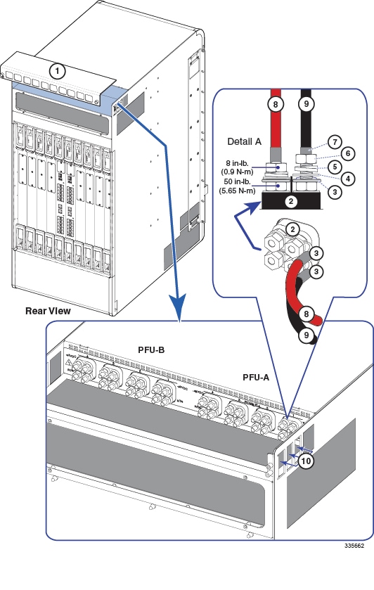
Each cable should be terminated with a 90 degree, 2-hole lug (supplied). Each feed consists of a supply (-48VDC) and return (RTN) cable. The feed cables terminate at the rear of each PFU on 0.25-inch posts spaced 0.63-inch on center.
Cable Routing
All feed cables must be routed through the openings at the upper rear sides of the chassis.
Method of Connection
The method of connection at each PFU terminal is: flat washer, lug, lock washer and nut (7/16-inch). The nut(s) must be torqued to 50 in-lb. (5.65 N-m).
Insulate Lugs
Use heat shrink tubing or non-conductive tape to insulate much of the exposed metal on the lug without interfering with the attachment point.
Crimp Lugs on Cables
Use the Panduit® lugs supplied with the chassis (LCD4-14AF-L). The lug must be crimped to the end of a ground cable using Panduit crimp tool part number CT-720-1 (die color: gray, P29). The wire strip length is 7/8-inch (22 mm).
Follow the OEM recommendations for preparing and crimping the lugs on the ends of each feed cable.
Connect Power Feeds to the PFUs
Caution | To avoid personal injury or possible equipment damage, ensure that the circuit breakers for all ASR 5500 chassis feeds from the power distribution panel are all set to OFF before attempting to attach power cables to the PFU(s). |
Caution | Verify that all circuit breakers on the front panels of both PFUs (four per PFU) are set to OFF before attaching power feed cables to the PFUs (see figure below). The breakers must remain OFF until the chassis is to be powered up. |
The eight power terminals on the back of each PFU are shipped with nuts and washers attached.