Configuring Layer 2 Protocol Tunneling
Prerequisites for Layer 2 Protocol Tunneling
The following sections list prerequisites and considerations for configuring Layer 2 protocol tunneling.
To configure Layer 2 point-to-point tunneling to facilitate the automatic creation of EtherChannels, you need to configure both the SP (service-provider) edge switch and the customer device.
Restrictions for Layer 2 Protocol Tunneling
Layer 2 protocol tunneling and native VLAN tagging are not supported on the same trunk port. If native VLAN tagging is enabled globally on the device and Layer 2 protocol tunneling needs to be enabled on a trunk port, disable native VLAN tagging on the trunk port using the no switchport trunk native vlan tag command before configuring Layer 2 protocol tunneling.
Information About Layer 2 Protocol Tunneling
The following sections provide information about Layer 2 protocol tunneling:
Layer 2 Protocol Tunneling Overview
Customers at different sites that are connected across a service-provider network need to use various Layer 2 protocols to scale their topologies to include all remote sites, as well as the local sites. STP must run properly, and every VLAN should build a proper spanning tree that includes the local site and all remote sites across the service-provider network. Cisco Discovery Protocol (CDP) must discover neighboring Cisco devices from local and remote sites. VLAN Trunking Protocol (VTP) must provide consistent VLAN configuration throughout all sites in the customer network.
When protocol tunneling is enabled, edge device on the inbound side of the service-provider network encapsulate Layer 2 protocol packets with a special MAC address and send them across the service-provider network. Core devices in the network do not process these packets but forward them as normal packets. Layer 2 protocol data units (PDUs) for CDP, STP, or VTP cross the service-provider network and are delivered to customer devices on the outbound side of the service-provider network. Identical packets are received by all customer ports on the same VLANs with these results:
-
Users on each of a customer’s sites can properly run STP, and every VLAN can build a correct spanning tree based on parameters from all sites and not just from the local site.
-
CDP discovers and shows information about the other Cisco devices that are connected through the service-provider network.
-
VTP provides consistent VLAN configuration throughout the customer network, propagating to all devices through the service provider.
Layer 2 protocol tunneling can be used independently or can enhance IEEE 802.1Q tunneling. If protocol tunneling is not enabled on IEEE 802.1Q tunneling ports, remote devices at the receiving end of the service-provider network do not receive the PDUs and cannot properly run STP, CDP, and VTP. When protocol tunneling is enabled, Layer 2 protocols within each customer’s network are totally separate from those running within the service-provider network. Customer devices on different sites that send traffic through the service-provider network with IEEE 802.1Q tunneling achieve complete knowledge of the customer’s VLAN. If IEEE 802.1Q tunneling is not used, you can still enable Layer 2 protocol tunneling by connecting to the customer device through access ports and by enabling tunneling on the service-provider access port.
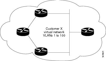
For example, in the following figure (Layer 2 Protocol Tunneling), Customer X has four switches in the same VLAN, that are connected through the service-provider network. If the network does not tunnel PDUs, switches on the far ends of the network cannot properly run STP, CDP, and VTP. For example, STP for a VLAN on a switch in Customer X, Site 1, will build a spanning tree on the switches at that site without considering convergence parameters based on Customer X’s switch in Site 2. This could result in the topology that is shown in the Layer 2 Network Topology without Proper Convergence figure.
Layer 2 Protocol Tunneling on Ports
You can enable Layer 2 protocol tunneling (by protocol) on the ports that are connected to the customer in the edge devices of the service-provider network. The service-provider edge devices connected to the customer device perform the tunneling process. Edge device tunnel ports are connected to customer IEEE 802.1Q trunk ports. Edge device access ports are connected to customer access ports. The edge devices connected to the customer device perform the tunneling process.
You can enable Layer 2 protocol tunneling on ports that are configured as access ports or tunnel ports or trunk ports. You cannot enable Layer 2 protocol tunneling on ports that are configured in either switchport mode dynamic auto mode (the default mode) or switchport mode dynamic desirable mode.
The device supports Layer 2 protocol tunneling for CDP, STP, and VTP. For emulated point-to-point network topologies, it also supports PAgP, LACP, LLDP, and UDLD protocols.
 Note |
PAgP, LACP, and UDLD protocol tunneling are only intended to emulate a point-to-point topology. An erroneous configuration that sends tunneled packets to many ports could lead to a network failure. |
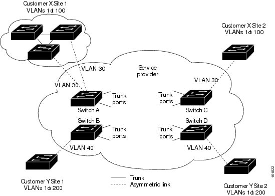
When the Layer 2 PDUs that entered the service-provider inbound edge device through a Layer 2 protocol-enabled port exit through the trunk port into the service-provider network, the device overwrites the customer PDU-destination MAC address with a well-known Cisco proprietary multicast address (01-00-0c-cd-cd-d0). If IEEE 802.1Q tunneling is enabled, packets are also double-tagged; the outer tag is the customer metro tag, and the inner tag is the customer’s VLAN tag. The core devices ignore the inner tags and forward the packet to all trunk ports in the same metro VLAN. The edge devices on the outbound side restore the proper Layer 2 protocol and MAC address information and forward the packets to all tunnel or access ports in the same metro VLAN. Therefore, the Layer 2 PDUs remain intact and are delivered across the service-provider infrastructure to the other side of the customer network.
See the Layer 2 Protocol Tunneling figure in Layer 2 Protocol Tunneling Overview, with Customer X and Customer Y in access VLANs 30 and 40, respectively. Asymmetric links connect the customers in Site 1 to edge switches in the service-provider network. The Layer 2 PDUs (for example, BPDUs) coming into Switch B from Customer Y in Site 1 are forwarded to the infrastructure as double-tagged packets with the well-known MAC address as the destination MAC address. These double-tagged packets have the metro VLAN tag of 40, as well as an inner VLAN tag (for example, VLAN 100). When the double-tagged packets enter Switch D, the outer VLAN tag 40 is removed, the well-known MAC address is replaced with the respective Layer 2 protocol MAC address, and the packet is sent to Customer Y on Site 2 as a single-tagged frame in VLAN 100.
You can also enable Layer 2 protocol tunneling on access ports on the edge switch that is connected to access or trunk ports on the customer switch. In this case, the encapsulation and decapsulation process are the same as described in the previous paragraph, except that the packets are not double-tagged in the service-provider network. The single tag is the customer-specific access VLAN tag.
In switch stacks, Layer 2 protocol tunneling configuration is distributed among all member switches. Each member switch that receives an ingress packet on a local port encapsulates or decapsulates the packet and forwards it to the appropriate destination port. On a single switch, ingress Layer 2 protocol-tunneled traffic is sent across all local ports in the same VLAN on which Layer 2 protocol tunneling is enabled. In a stack, packets received by a Layer 2 protocol-tunneled port are distributed to all ports in the stack that are configured for Layer 2 protocol tunneling and are in the same VLAN. All Layer 2 protocol tunneling configuration is handled by the active switch and distributed to all member switches in the stack.
Layer 2 Protocol Tunneling for EtherChannels
In an SP network, you can use Layer 2 protocol tunneling to enhance the creation of EtherChannels by emulating a point-to-point network topology. When you enable protocol tunneling (PAgP or LACP) on the SP switch, remote customer switches receive the PDUs and can negotiate the automatic creation of EtherChannels.
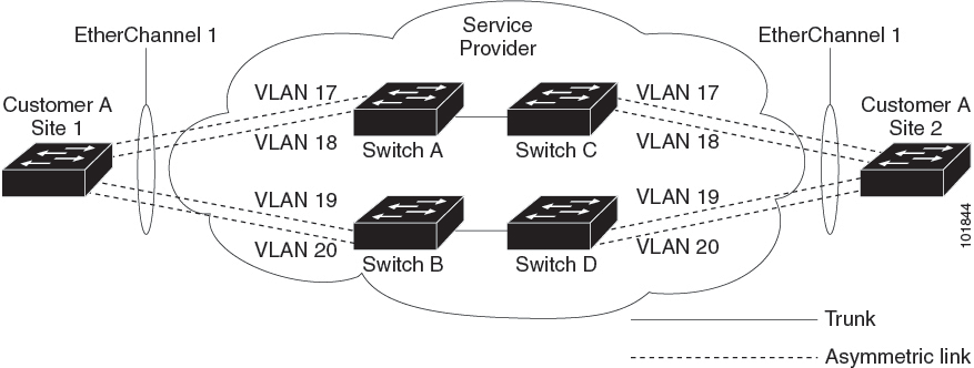
For example, in the following figure (Layer 2 Protocol Tunneling for EtherChannels), Customer A has two switches in the same VLAN that are connected through the SP network. When the network tunnels PDUs, switches on the far ends of the network can negotiate the automatic creation of EtherChannels without needing dedicated lines.
While configuring Layer 2 Protocol Tunneling on trunk ports, both the trunk ports on the SP edge device should be configured with different native VLANs. The native VLAN of one trunk port should not be in the list of allowed VLANs of the other trunk port to avoid loops.
Default Layer 2 Protocol Tunneling Configuration
The following table shows the default Layer 2 protocol tunneling configuration.
|
Feature |
Default Setting |
|---|---|
|
Layer 2 protocol tunneling |
Disabled. |
|
Shutdown threshold |
None set. |
|
Drop threshold |
None set. |
How to Configure Layer 2 Protocol Tunneling
The following section provides configuration information on how to configure a layer 2 protocol tunnel:
Configuring Layer 2 Protocol Tunneling
Procedure
| Command or Action | Purpose | |||||
|---|---|---|---|---|---|---|
|
Step 1 |
enable Example: |
Enables privileged EXEC mode. Enter your password if prompted. |
||||
|
Step 2 |
configure terminal Example: |
Enters global configuration mode. |
||||
|
Step 3 |
interface interface-id Example: |
Specifies the interface that is connected to the phone, and enters interface configuration mode. |
||||
|
Step 4 |
Use one of the following:
Example: |
Configures the interface as an IEEE 802.1Q tunnel port or a trunk port. |
||||
|
Step 5 |
l2protocol-tunnel [cdp | lldp | point-to-point | stp | vtp] Example: |
Enables protocol tunneling for the desired protocol. If no keyword is entered, tunneling is enabled for all four Layer 2 protocols.
|
||||
|
Step 6 |
l2protocol-tunnel shutdown-threshold [ packet_second_rate_value | cdp | lldp point-to-point | stp | vtp] Example: |
(Optional) Configures the threshold for packets-per-second that are accepted for encapsulation. The interface is disabled if the configured threshold is exceeded. If no protocol option is specified, the threshold applies to each of the tunneled Layer 2 protocol types. The range is 1 to 4096. The default is to have no threshold configured.
|
||||
|
Step 7 |
l2protocol-tunnel drop-threshold [ packet_second_rate_value | cdp | lldp | point-to-point | stp | vtp] Example: |
(Optional) Configures the threshold for packets-per-second that are accepted for encapsulation. The interface drops packets if the configured threshold is exceeded. If no protocol option is specified, the threshold applies to each of the tunneled Layer 2 protocol types. The range is 1 to 4096. The default is to have no threshold configured.
|
||||
|
Step 8 |
exit Example: |
Returns to global configuration mode. |
||||
|
Step 9 |
errdisable recovery cause l2ptguard Example: |
(Optional) Configures the recovery mechanism from a Layer 2 maximum-rate error so that the interface is reenabled and can try again. Errdisable recovery is disabled by default; when enabled, the default time interval is 300 seconds. |
||||
|
Step 10 |
spanning-tree bpdufilter enable Example: |
Inserts a BPDU filter for spanning tree.
|
||||
|
Step 11 |
end Example: |
Returns to privileged EXEC mode. |
||||
|
Step 12 |
show l2protocol Example: |
Displays the Layer 2 tunnel ports on the device, including the protocols configured, the thresholds, and the counters. |
||||
|
Step 13 |
copy running-config startup-config Example: |
(Optional) Saves your entries in the configuration file. |
How to Configure Layer 2 Protocol Tunneling for EtherChannels
For EtherChannels, you need to configure both the SP (service-provider) edge devices and the customer devices for Layer 2 protocol tunneling. The following sections provide configuration information on how to configure the SP edge device and how to configure the customer device:
Configuring the SP Edge Switch
Procedure
| Command or Action | Purpose | |||||
|---|---|---|---|---|---|---|
|
Step 1 |
enable Example: |
Enables privileged EXEC mode. Enter your password if prompted. |
||||
|
Step 2 |
configure terminal Example: |
Enters global configuration mode. |
||||
|
Step 3 |
interface interface-id Example: |
Specifies the interface that is connected to the phone, and enters interface configuration mode. |
||||
|
Step 4 |
switchport trunk native vlan vlan-id Example: |
Configures the native VLAN.
|
||||
|
Step 5 |
switchport trunk allowed vlan vlan-id list Example: |
Specifies the list of allowed VLANs.
|
||||
|
Step 6 |
Use one of the following:
Example:or |
Configures the interface as an IEEE 802.1Q tunnel port or as a trunk port. |
||||
|
Step 7 |
l2protocol-tunnel point-to-point [pagp | lacp | udld] Example: |
(Optional) Enables point-to-point protocol tunneling for the desired protocol. If no keyword is entered, tunneling is enabled for all three protocols.
|
||||
|
Step 8 |
l2protocol-tunnel shutdown-threshold [point-to-point [pagp | lacp | udld]] value Example: |
(Optional) Configures the threshold for packets-per-second that are accepted for encapsulation. The interface is disabled if the configured threshold is exceeded. If no protocol option is specified, the threshold applies to each of the tunneled Layer 2 protocol types. The range is 1 to 4096. The default is to have no threshold configured.
|
||||
|
Step 9 |
l2protocol-tunnel drop-threshold [point-to-point [pagp | lacp | udld]] value Example: |
(Optional) Configures the threshold for packets-per-second that are accepted for encapsulation. The interface drops packets if the configured threshold is exceeded. If no protocol option is specified, the threshold applies to each of the tunneled Layer 2 protocol types. The range is 1 to 4096. The default is to have no threshold configured.
|
||||
|
Step 10 |
no cdp enable Example: |
Disables CDP on the interface. |
||||
|
Step 11 |
spanning-tree bpdu filter enable Example: |
Enables BPDU filtering on the interface. |
||||
|
Step 12 |
exit Example: |
Returns to global configuration mode. |
||||
|
Step 13 |
errdisable recovery cause l2ptguard Example: |
(Optional) Configures the recovery mechanism from a Layer 2 maximum-rate error so that the interface is reenabled and can try again. Errdisable recovery is disabled by default; when enabled, the default time interval is 300 seconds. |
||||
|
Step 14 |
end Example: |
Returns to privileged EXEC mode. |
||||
|
Step 15 |
show l2protocol Example: |
Displays the Layer 2 tunnel ports on the device, including the protocols configured, the thresholds, and the counters. |
||||
|
Step 16 |
copy running-config startup-config Example: |
(Optional) Saves your entries in the configuration file. |
Configuring the Customer Device
Before you begin
For EtherChannels, you need to configure both the SP edge device and the customer device for Layer 2 protocol tunneling.
Procedure
| Command or Action | Purpose | |||
|---|---|---|---|---|
|
Step 1 |
enable Example: |
Enables privileged EXEC mode. Enter your password if prompted. |
||
|
Step 2 |
configure terminal Example: |
Enters global configuration mode. |
||
|
Step 3 |
interface interface-id Example: |
Specifies the interface that is connected to the phone, and enters interface configuration mode. |
||
|
Step 4 |
switchport trunk encapsulation dot1q Example: |
Sets the trunking encapsulation format to IEEE 802.1Q. |
||
|
Step 5 |
switchport mode trunk Example: |
Enables trunking on the interface. |
||
|
Step 6 |
udld port Example: |
Enables UDLD in normal mode on the interface. |
||
|
Step 7 |
channel-group channel-group-number mode desirable Example: |
Assigns the interface to a channel group, and specifies desirable for the PAgP mode. |
||
|
Step 8 |
exit Example: |
Returns to global configuration mode. |
||
|
Step 9 |
interface port-channel port-channel number Example: |
Enters port-channel interface mode. |
||
|
Step 10 |
shutdown Example: |
Shuts down the interface. |
||
|
Step 11 |
no shutdown Example: |
Enables the interface. |
||
|
Step 12 |
end Example: |
Returns to privileged EXEC mode. |
||
|
Step 13 |
show l2protocol Example: |
Displays the Layer 2 tunnel ports on the device, including the protocols configured, the thresholds, and the counters. |
||
|
Step 14 |
copy running-config startup-config Example: |
(Optional) Saves your entries in the configuration file.
|
Configuration Examples for Layer 2 Protocol Tunneling
The following sections provide various configuration examples for layer 2 protocol tunneling:
Example: Configuring Layer 2 Protocol Tunneling
The following example shows how to configure Layer 2 protocol tunneling for Cisco Discovery Protocol, STP, and VTP and to verify the configuration.
Device(config)# interface gigabitethernet1/0/11
Device(config-if)# l2protocol-tunnel cdp
Device(config-if)# l2protocol-tunnel stp
Device(config-if)# l2protocol-tunnel vtp
Device(config-if)# l2protocol-tunnel shutdown-threshold 1500
Device(config-if)# l2protocol-tunnel drop-threshold 1000
Device(config-if)# exit

Device(config)# end
Device# show l2protocol

Port Protocol Shutdown Drop Encapsulation Decapsulation Drop
Threshold Threshold Counter Counter Counter
------- -------- --------- --------- ------------- ------------- -------------
Gi0/11 cdp 1500 1000 2288 2282 0
stp 1500 1000 116 13 0
vtp 1500 1000 3 67 0
pagp ---- ---- 0 0 0
lacp ---- ---- 0 0 0
udld ---- ---- 0 0 0
Examples: Configuring the SP Edge and Customer Switches
This example shows how to configure the SP edge switch 1 and edge switch 2. VLANs 17, 18, 19, and 20 are the access VLANs, Fast Ethernet interfaces 1 and 2 are point-to-point tunnel ports with PAgP and UDLD enabled, the drop threshold is 1000, and Fast Ethernet interface 3 is a trunk port.
SP edge switch 1 configuration:
Device(config)# interface gigabitethernet1/0/1
Device(config-if)# switchport access vlan 17
Device(config-if)# switchport mode dot1q-tunnel
Device(config-if)# l2protocol-tunnel point-to-point pagp
Device(config-if)# l2protocol-tunnel point-to-point udld
Device(config-if)# l2protocol-tunnel drop-threshold point-to-point pagp 1000
Device(config-if)# exit
Device(config)# interface gigabitethernet1/0/2
Device(config-if)# switchport access vlan 18
Device(config-if)# switchport mode dot1q-tunnel
Device(config-if)# l2protocol-tunnel point-to-point pagp
Device(config-if)# l2protocol-tunnel point-to-point udld
Device(config-if)# l2protocol-tunnel drop-threshold point-to-point pagp 1000
Device(config-if)# exit
Device(config)# interface gigabitethernet1/0/3
Device(config-if)# switchport trunk encapsulation isl
Device(config-if)# switchport mode trunk
SP edge switch 2 configuration:
Device(config)# interface gigabitethernet1/0/1
Device(config-if)# switchport access vlan 19
Device(config-if)# switchport mode dot1q-tunnel
Device(config-if)# l2protocol-tunnel point-to-point pagp
Device(config-if)# l2protocol-tunnel point-to-point udld
Device(config-if)# l2protocol-tunnel drop-threshold point-to-point pagp 1000
Device(config-if)# exit
Device(config)# interface gigabitethernet1/0/2
Device(config-if)# switchport access vlan 20
Device(config-if)# switchport mode dot1q-tunnel
Device(config-if)# l2protocol-tunnel point-to-point pagp
Device(config-if)# l2protocol-tunnel point-to-point udld
Device(config-if)# l2protocol-tunnel drop-threshold point-to-point pagp 1000
Device(config-if)# exit
Device(config)# interface gigabitethernet1/0/3
Device(config-if)# switchport trunk encapsulation isl
Device(config-if)# switchport mode trunk
This example shows how to configure the customer switch at Site 1. Fast Ethernet interfaces 1, 2, 3, and 4 are set for IEEE 802.1Q trunking, UDLD is enabled, EtherChannel group 1 is enabled, and the port channel is shut down and then enabled to activate the EtherChannel configuration.
Device(config)# interface gigabitethernet1/0/1
Device(config-if)# switchport trunk encapsulation dot1q
Device(config-if)# switchport mode trunk
Device(config-if)# udld enable
Device(config-if)# channel-group 1 mode desirable
Device(config-if)# exit
Device(config)# interface gigabitethernet1/0/2
Device(config-if)# switchport trunk encapsulation dot1q
Device(config-if)# switchport mode trunk
Device(config-if)# udld enable
Device(config-if)# channel-group 1 mode desirable
Device(config-if)# exit
Device(config)# interface gigabitethernet1/0/3
Device(config-if)# switchport trunk encapsulation dot1q
Device(config-if)# switchport mode trunk
Device(config-if)# udld enable
Device(config-if)# channel-group 1 mode desirable
Device(config-if)# exit
Device(config)# interface gigabitethernet1/0/4
Device(config-if)# switchport trunk encapsulation dot1q
Device(config-if)# switchport mode trunk
Device(config-if)# udld enable
Device(config-if)# channel-group 1 mode desirable
Device(config-if)# exit
Device(config)# interface port-channel 1
Device(config-if)# shutdown
Device(config-if)# no shutdown
Device(config-if)# exit
Monitoring Tunneling Status
The following table describes the commands used to monitor tunneling status.
|
Command |
Purpose |
|---|---|
|
clear l2protocol-tunnel counters |
Clears the protocol counters on Layer 2 protocol tunneling ports. |
|
show dot1q-tunnel |
Displays IEEE 802.1Q tunnel ports on the device. |
|
show dot1q-tunnel interface interface-id |
Verifies if a specific interface is a tunnel port. |
|
show l2protocol-tunnel |
Displays information about Layer 2 protocol tunneling ports. |
|
show errdisable recovery |
Verifies if the recovery timer from a Layer 2 protocol-tunnel error disable state is enabled. |
|
show l2protocol-tunnel interface interface-id |
Displays information about a specific Layer 2 protocol tunneling port. |
|
show l2protocol-tunnel summary |
Displays only Layer 2 protocol summary information. |
|
show vlan dot1q tag native |
Displays the status of native VLAN tagging on the device. |
Feature History for Layer 2 Protocol Tunneling
This table provides release and related information for features explained in this module.
These features are available on all releases subsequent to the one they were introduced in, unless noted otherwise.
|
Release |
Feature |
Feature Information |
|---|---|---|
|
Cisco IOS XE Gibraltar 16.12.1 |
Layer 2 Protocol Tunneling |
Layer 2 protocols allow you to scale topologies to include all remote sites and local sites. |
Use Cisco Feature Navigator to find information about platform and software image support. To access Cisco Feature Navigator, go to http://www.cisco.com/go/cfn.