Contents
- Configuring PRP
- Information About PRP
- Role of the Switch
- PRP Channels
- Mixed Traffic and Supervisory Frames
- Prerequisites
- Guidelines and Limitations
- Default Settings
- Creating a PRP Channel and Group
- Adding Static Entries to the Node and VDAN Tables
- Clearing All Node Table and VDAN Table Dynamic Entries
- (Optional) General Usage Precision Time Protocol (PTP) Enable on LAN A Channel
- Disabling the PRP Channel and Group
- Verifying Configuration
- Related Documents
- Feature History
Configuring PRP
This document provides details about configuring Parallel Redundancy Protocol (PRP) on the Cisco Industrial Ethernet 2000U Series Switches (IE 2000U).
 Note | PRP is supported on multiple IE platforms, and PRP feature support may vary by platform. For details, refer to Feature History. Be sure to use the configuration guide for your IE platform. |
Information About PRP
Parallel Redundancy Protocol (PRP) is defined in the International Standard IEC 62439-3. PRP is designed to provide hitless redundancy (zero recovery time after failures) in Ethernet networks.
To recover from network failures, redundancy can be provided by network elements connected in mesh or ring topologies using protocols like RSTP, REP, or MRP, where a network failure causes some reconfiguration in the network to allow traffic to flow again (typically by opening a blocked port). These schemes for redundancy can take between a few milliseconds to a few seconds for the network to recover and traffic to flow again.
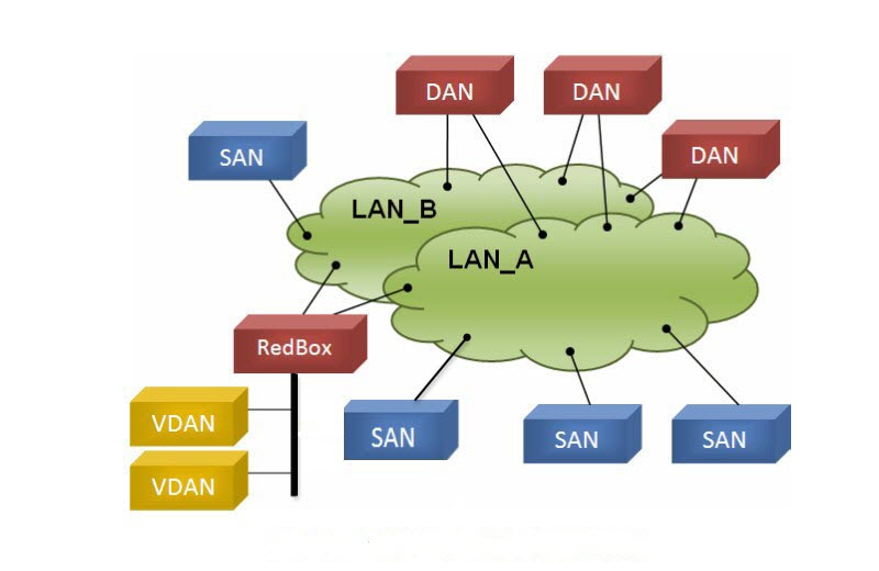
PRP uses a different scheme, where the end nodes implement redundancy (instead of network elements) by connecting two network interfaces to two independent, disjointed, parallel networks (LAN-A and LAN-B). Each of these Dually Attached Nodes (DANs) then have redundant paths to all other DANs in the network.
The DAN sends two packets simultaneously through its two network interfaces to the destination node. A redundancy control trailer (RCT), which includes a sequence number, is added to each frame to help the destination node distinguish between duplicate packets. When the destination DAN receives the first packet successfully, it removes the RCT and consumes the packet. If the second packet arrives successfully, it is discarded. If a failure occurs in one of the paths, traffic continues to flow over the other path uninterrupted, and zero recovery time is required.
Non-redundant endpoints in the network that attach only to either LAN-A or LAN-B are known as Singly Attached Nodes (SANs).
A Redundancy Box (RedBox) is used when an end node that does not have two network ports and does not implement PRP needs to implement redundancy. Such an end node can connect to a RedBox, which provides connectivity to the two different networks on behalf of the device. Because a node behind a RedBox appears for other nodes like a DAN, it is called a Virtual DAN (VDAN). The RedBox itself is a DAN and acts as a proxy on behalf of its VDANs.
Role of the Switch
The IE 2000U switch implements RedBox functionality. A switch operating with PRP has a Gigabit Ethernet or Fast Ethernet uplink port connection to each of the two LANs.
PRP Channels
PRP channel or channel group is a logical interface that aggregates two Gigabit Ethernet interfaces (access, trunk, or routed) into a single link. In the channel group, the lower numbered Gigabit Ethernet member port is the primary port and connects to LAN_A.
The higher numbered port is the secondary port and connects to LAN_B. The PRP channel remains up as long as at least one of these member ports remains up and sends traffic. When both member ports are down, the channel is down.
The total number of supported PRP channel groups is 2, depending on the IE 2000U platform, and the interfaces that can be utilized for each group on the switch are fixed. The following table lists the PRP channels and interfaces supported for the IE 2000U platforms.
|
IE 2000U Platform |
Supported PRP Channels |
Supported Interfaces |
|---|---|---|
|
6-port SKUs (IE-2000U-4TS-G, IE-2000U-4T-G, and IE-2000U-4S-G) |
PRP not supported |
PRP not supported |
|
10-port SKUs (IE-2000U-8TC-G) |
PRP channel 1, no PRP channel 2 |
GigabitEthernet0/1 and GigabitEthernet0/2 for PRP channel 1 |
|
20-port non-PoE SKUs (IE-2000U-16TC-G, IE-2000U-16TC-G-X) |
PRP channel 1, PRP channel 2 |
GigabitEthernet0/1 and GigabitEthernet0/2 for PRP channel 1 FastEthernet0/17 and FastEthernet0/18 for PRP channel 2 |
|
18-port PoE SKUs (IE-2000U-16TC-GP) |
PRP channel 1, no PRP channel 2 |
GigabitEthernet0/1 and GigabitEthernet0/2 for PRP channel 1 |
Mixed Traffic and Supervisory Frames
Traffic egressing the RedBox PRP channel group can be mixed, that is, destined to either SANs (connected only on either LAN-A or LAN-B) or DANs. To avoid duplication of packets for SANs, the switch learns source MAC addresses from received Supervision frames for DAN entries and source MAC addresses from non-PRP (regular traffic) frames for SAN entries and maintains these addresses in the node table. When forwarding packets out the PRP channel to SAN MAC addresses, the switch looks up the entry and determines which LAN to send to rather than duplicating the packet.
A RedBox with VDANs needs to send supervisory frames on behalf of those VDANs. For traffic coming in on all other ports and going out PRP channel ports, the switch learns source MAC addresses, adds them to the VDAN table, and starts sending Supervisory frames for these addresses. Learned VDAN entries are subject to aging.
You can add static entries to the node and VDAN tables as described in Adding Static Entries to the Node and VDAN Tables. You can also display the node and VDAN tables and clear entries. See Verifying Configuration and Clearing All Node Table and VDAN Table Dynamic Entries.
Prerequisites
-
You must have FPGA version 3.6 or greater to support PRP.
Note
Note: To check the FPGA version, use the show version command. For example:Switch#show version | inc FPGA Backplane FPGA version : 3.6 Switch#
-
Not all versions of IE 2000U support the PRP feature and not all industrial platforms support all features. For details, refer to PRP Channels and Feature History.
Guidelines and Limitations
-
You can configure PRP on Gigabit Ethernet and Fast Ethernet uplink interfaces, depending on the IE 2000U platform. See PRP Channels for details about interface support on IE 2000U platforms.
-
Up to 2 PRP channels are supported on the IE 2000U 16-port switches with the exception of the IE-2000U-16TC-GP, which supports only one PRP channel. See PRP Channels for details about PRP channel support on IE 2000U platforms.
-
PRP traffic load cannot exceed 90% bandwidth of the Gigabit Ethernet and Fast Ethernet interface channels.
-
Because PRP DANs and RedBoxes add a 6-byte PRP trailer to the packet, PRP packets can be dropped by some switches with a maximum transmission unit (MTU) size of 1500. To ensure that all packets can flow through the PRP network, increase the MTU size for switches within the PRP LAN-A and LAN-B network to 1506 as follows:
-
system mtu 1506
-
system mtu jumbo 1506
-
-
A PRP channel must have two active ports configured within a channel to remain active and maintain redundancy.
-
Both interfaces within a channel group must have the same configuration.
-
For Layer 3, you must configure the IP address on the PRP channel interface.
-
Precision Time Protocol (PTP), when enabled, traverses PRP within LAN A only.
-
Load-balancing is not supported.
-
LLDP and CDP must be disabled on interfaces where PRP is enabled.
-
UDLD must be disabled on interfaces where PRP is enabled, especially if the interfaces have media-type sfp.
-
The spanning-tree bpdufilter enable command is required on the prp-channel interface. Spanning-tree BPDU filter drops all ingress/egress BPDU traffic. This command is required to create independent spanning-tree domains (zones) in the network.
-
The spanning-tree portfast edge trunk command is optional on the prp-channel interface but highly-recommended. It improves the spanning-tree converge time in PRP LAN-A and LAN-B.
-
The show interface g0/1 or show interface g0/2 command should not be used to read PRP statistics if these interfaces are PRP channel members because the counter information can be misleading. Use the show interface prp-channel [1 | 2] command instead.
-
Primary links, GigabitEthernet0/1 and FastEthernet0/1, should not be shut down.
-
PRP member interfaces should not be shut down.
If you attempt to execute shut on a PRP member interface, the following message is displayed:
switch(config)#int gi 0/2
switch(config-if)#shut
?%Interface GigabitEthernet0/2 is configured in PRP-channel group, shutdown not permitted!?
-
When a link, LAN A (Gi 1/1) or LAN B (Gi 1/2) goes down, show interface status continues to show a status of UP for the link. Use the show prp channel command to confirm the status of the links, which indicates if a link is down (CSCva06447).
show prp channel 1 detail
PRP-channel: PR1
------------
Layer type = L2
Ports: 2 Maxports = 2
Port state = prp-channel is Inuse
Protocol = Enabled
Ports in the group:
1) Port: Gi0/1
Logical slot/port = 0/1 Port state = Inuse
Protocol = Enabled
2) Port: Gi0/2
Logical slot/port = 0/2 Port state = Not-Inuse (link down)
Protocol = Enabled
Node and VDAN Tables
-
The switch supports up to 512 (SAN+DANP) entries in the node table.
-
Hash collisions can limit the number of MAC addresses. If the node table is out of resources for learning a MAC address from a node, the switch defaults to treating that node as a DAN.
-
After reload (before any MAC address is learned), the switch temporarily treats the unlearned node as a DAN and duplicate the egress packets until an ingress packet or supervision frame is received from the node to populate an entry into the node table.
-
The switch supports up to 512 VDAN entries in the VDAN table. If the VDAN table is full, the switch cannot send Supervisory frames for new VDANS.
Creating a PRP Channel and Group
-
Review the maximum number of PRP channels and specific interfaces supported per switch type, described in PRP Channels.
-
Review the Prerequisites and Guidelines and Limitations.
-
Ensure that the member interfaces of a PRP channel are not participating in any redundancy protocols such as FlexLinks, EtherChannel, REP, and so on before creating a PRP channel.
| Step 1 | Enter global configuration mode:
configure terminal | ||||
| Step 2 | Assign either two Gigabit Ethernet interfaces or two Fast Ethernet interfaces to the PRP channel group:
interface range { GigabitEthernet0/1-2 | FastEthernet0/17-18 } Use the no interface prp-channel 1|2 command to disable PRP on the defined interfaces and shut down the interfaces.
| ||||
| Step 3 | (Optional) For Layer 2 traffic, enter switchport. (Default):
switchport
| ||||
| Step 4 | (Optional) Set a non-trunking, non-tagged single VLAN Layer 2 (access) interface:
switchport mode access | ||||
| Step 5 | (Optional) Create a VLAN for the Gi0/1-2 interfaces:
switchport access vlan <value>
| ||||
| Step 6 | Disable Precision Time Protocol (PTP) on the switch:
no ptp enable | ||||
| Step 7 | Disable loop detection for the redundancy channel:
no keepalive | ||||
| Step 8 | Disable UDLD for the redundancy channel:
udld port disable | ||||
| Step 9 | Enter sub-interface mode and create a PRP channel group:
prp-channel-group prp-channel group prp-channel group—Value of 1 or 2 The two interfaces that you assigned in step 2 are assigned to this channel group. | ||||
| Step 10 | Bring up the PRP channel:
no shutdown | ||||
| Step 11 | Specify the PRP interface and enter interface mode:
interface prp-channel prp-channel-number prp-channel-number—Value of 1 or 2 | ||||
| Step 12 | Configure bpdufilter on the prp-channel interface:
spanning-tree bpdufilter enable Spanning-tree BPDU filter drops all ingress/egress BPDU traffic. This command is required to create independent spanning-tree domains (zones) in the network. | ||||
| Step 13 | (Optional) Configure LAN-A/B ports to quickly get to FORWARD mode:
spanning-tree portfast edge trunk This command is optional but highly recommended. It improves the spanning-tree convergence time on PRP RedBoxes and LAN-A and LAN-B switch edge ports. It is also highly recommended to configure this command on the LAN_A/LAN_B ports directly connected to a RedBox PRP interface. |
This example shows how to create a PRP channel on a switch, create a PRP channel group, and assign two ports to that group.
switch# configure terminal
switch(config)# interface range GigabitEthernet0/1-2
switch(config-if)# no ptp enable
switch(config-if)# no keepalive
switch(config-if)# udld port disable
switch(config-if)# prp-channel-group 1
switch(config-if)# no shutdown
switch(config-if)# spanning-tree bpdufilter enable
This example shows how to create a PRP channel on the switch with a VLAN ID of 2.
switch# configure terminal
switch(config)# interface range GigabitEthernet0/1-2
switch(config-if)# switchport
switch(config-if)# switchport mode access
switch(config-if)# switchport access vlan 2
switch(config-if)# no ptp enable
switch(config-if)# no keepalive
switch(config-if)# udld port disable
switch(config-if)# prp-channel-group 1
switch(config-if)# no shutdown
switch(config-if)# spanning-tree bpdufilter enable
This example shows how to create a PRP channel on a switch configured with Layer 3.
switch# configure terminal
switch(config)# interface range GigabitEthernet0/1-2
switch(config-if)# no switchport
switch(config-if)# no ptp enable
switch(config-if)# no keepalive
switch(config-if)# udld port disable
switch(config-if)# prp-channel-group 1
switch(config-if)# no shutdown
switch(config-if)# spanning-tree bpdufilter enable
switch(config-if)# exit
switch(config)# interface prp-channel 1
switch(config)# ip address 192.0.0.2 255.255.255.0
Adding Static Entries to the Node and VDAN Tables
See Mixed Traffic and Supervisory Frames and the guidelines for node and VDAN tables in Guidelines and Limitations.
Configure the PRP channel and group as described in Creating a PRP Channel and Group.
| Step 1 | Enter global configuration mode:
configure terminal | ||
| Step 2 | Specify the MAC address to add to the node table for the channel group and whether the node is a DAN or a SAN (attached to either LAN A or LAN B):
prp channel-group prp-channel group nodeTableMacaddress mac-address {dan | lan-a | lan-b} prp-channel group —Value of 1 or 2 mac-address— MAC address of the node
| ||
| Step 3 | Specify the MAC address to add to the VDAN table:
prp channel-group prp-channel group vdanTableMacaddress mac-address prp-channel group—Value of 1 or 2 mac-address—Mac address of the node or VDAN
|
switch# configure terminal
switch(config-if)# prp channel-group 1 nodeTableMacaddress 0000.0000.0001 lan-a
Clearing All Node Table and VDAN Table Dynamic Entries
The clear prp node-table and clear prp vdan-table commands clear only dynamic entries. To clear static entries, use the no form of the nodeTableMacaddress or vdanTableMacaddress commands shown in Adding Static Entries to the Node and VDAN Tables.
| Step 1 | To clear all dynamic entries in the node table, enter
clear prp node-table [channel-groupgroup] |
| Step 2 | To clear all dynamic entries in the VDAN table, enter
clear prp vdan-table [channel-group group] If you do not specify a channel group, the dynamic entries are cleared for all PRP channel groups. |
(Optional) General Usage Precision Time Protocol (PTP) Enable on LAN A Channel
PTP traffic traverses PRP within LAN A only. Follow the steps in this procedure to enable PTP on LAN A.
Note | If LAN-A goes down due to a failure, PTP communication can no longer continue and PTP synchronization is lost, even though there might be a path available to the grandmaster clock through LAN-B. |
| Step 1 | Enter global configuration mode:
configure terminal |
| Step 2 | Specify the two Gigabit Ethernet interfaces in the PRP channel that you want to modify and enter interface mode:
interface range {gi0/1-2 | fe0/17-18} |
| Step 3 | Enable PTP on the interface:
ptp enable |
| Step 4 | Exit interface mode:
exit |
Disabling the PRP Channel and Group
| Step 1 | Enter global configuration mode:
configure terminal |
| Step 2 | Disable the PRP channel:
no interface prp-channel prp-channel-number |
| Step 3 | Exit interface mode:
exit |
Verifying Configuration
|
Command |
Purpose |
|---|---|
| show prp statistics {egressPacketStatistics | pauseFrameStatistics | nodeTableStatistics | ingressPacketStatistics | ptpPacketStatistics} | Displays statistics for PRP components. |
| show prp control {prpProfile | ptpLanOption | supervisionFrameOption | supervisionFrameTime | supervisionFrameLeifCheckInternal | supervisionFrameRedboxMacaddress | pauseFrameTime} | Displays PRP control information. |
| show prp channel {1 | 2} [detail | status | summary] | detail | status | summary]} | Displays configuration details for a specified PRP channel. |
| show control | Displays PRP control information VDAN table and supervision frame information. |
| show statistics | Displays ingress, egress, node table, and pause frame statistics. |
| show prp node-table [channel-group <group>] | Displays PRP node table. |
| show prp vdan-table [channel-group <group>] | Displays PRP VDAN table. |
Example
The following example shows the output for show prp channel when one of the interfaces in the PRP channel is down:
show prp channel 1 detail
PRP-channel: PR1
------------
Layer type = L2
Ports: 2 Maxports = 2
Port state = prp-channel is Inuse
Protocol = Enabled
Ports in the group:
1) Port: Gi0/1
Logical slot/port = 0/1 Port state = Inuse
Protocol = Enabled
2) Port: Gi0/2
Logical slot/port = 0/2 Port state = Not-Inuse (link down)
Protocol = Enabled
The following example shows how to display the PRP node table and PRP VDAN table:
Switch#show prp node-table
PRP Channel 1 Node Table
==================================
   Mac Address   Type  Dyn   TTL
---------------- ----- --- -------
 B0AA.7786.6781  lan-a  Y     59
 F454.3317.DC91  dan    Y     60
==================================
Channel 1 Total Entries: 2
Switch#show prp vdan-table
PRP Channel 1 VDAN Table
============================
   Mac Address   Dyn   TTL
---------------- --- -------
 F44E.05B4.9C81   Y     60
============================
Channel 1 Total Entries: 1
Related Documents
-
Cisco Industrial Ethernet 2000U Series Switches Configuration Guides
-
Parallel Redundancy Protocol (PRP) for IE 4000, IE 4010, and IE 5000 Switches
-
IEC 62439-3, Industrial communication networks - High availability automation networks - Part 3: Parallel Redundancy Protocol (PRP) and High-availability Seamless Redundancy (HSR)
Feature History
PRP is supported on IE 2000U, IE 4000, IE 4010, and IE 5000 switches. Not all versions of IE 2000U support the PRP feature, and not all industrial platforms support all features. The following table lists the PRP features supported by each platform.
|
Feature Name |
Release |
Feature Information |
||
|---|---|---|---|---|
|
Precision Time Protocol (PTP) over Parallel Redundancy Protocol (PRP) |
Cisco IOS Release 15.2(6)E |
Supported on IE 4000, IE 4010, and IE 5000. |
||
|
Parallel Redundancy Protocol Enhancements (Supervisor frame/ Mixed traffic support) |
Cisco IOS Release 15.2(5)E |
Supported on IE 2000U, IE 4000, and IE 5000. |
||
|
Parallel Redundancy Protocol including PRP mode LED. |
Cisco IOS Release 15.2(4)EC |
Initial support on IE 4010. |
||
|
Cisco IOS Release 15.2(2)EB |
Initial support on IE 5000. |
|||
|
Cisco IOS Release 15.2(2)EA |
Initial support on IE 4000. |
|||
|
Parallel Redundancy Protocol |
Cisco IOS Release 15.0(2)EK |
Initial support on the following IE 2000U platforms: IE-2000U-8TC-G , IE-2000U-16TC-G, IE-2000U-16TC-GP, IE-2000U-16TC-G-X
|
Copyright © 2013-2018, Cisco Systems, Inc. All rights reserved.