Contents
- Cisco ASR 902 and ASR 902U Aggregation Services Router Quick Start Guide
- Overview
- Overview
- Power Supply Features
- Fan Tray Features
- RSP Modules
- Supported RSP Features
- Network Timing Interfaces
- GNSS Module (A900-CM-GNSS)
- GNSS Module RF Input Requirements
- Interface Modules
- Installing the Cisco ASR 902 Router
- Installing the Chassis Brackets
- Installing the Router Chassis in the Rack
- Installing the Chassis Ground Connection
- Installing the Fan Tray
- Installing the Dust Filter
- RSP Installation
- Installing an RSP Module
- Interface Module Installation
- Installing an Interface Module
- Installing a DC Power Supply
- Installing a DC Power Supply Module
- Activating a DC Power Supply
- Installing an AC Power Supply Module
- Connecting a Cisco ASR 902 Router to the Network
- Connecting Console Cables
- Connecting to the USB Serial Port Using Microsoft Windows
- Powering Up the Cisco Router
- Verifying the Front Panel LEDs
- Verifying the Hardware Configuration
- Checking Hardware and Software Compatibility
- Configuring the Cisco Router at Startup
- Accessing the CLI Using the Console
- Configuring Global Parameters
- Checking the Running Configuration Settings
- Saving the Running Configuration to NVRAM
- Safely Powering Off the Cisco Router
- Related Documents
Cisco ASR 902 and ASR 902U Aggregation Services Router Quick Start Guide
 Note | The Cisco ASR 902 Router and the Cisco ASR 902U Router are collectively referred to as the Cisco ASR 902 Router in this document. Any differences between the routers are specifically called out. |
The Cisco ASR 902 Router is a fully-featured aggregation platform designed for the cost-effective delivery of converged mobile and business services. With shallow depth, low power consumption, and an extended temperature range, this compact 2-rack-unit (RU) router provides high service scale, full redundancy, and flexible hardware configuration.
Overview
Note | The Cisco ASR 902 Router and the Cisco ASR 902U Router are collectively referred to as the Cisco ASR 902 Router in this document. Any differences between the routers are specifically called out. |
The Cisco ASR 902 Router is a full-featured aggregation platform designed for cost-effective delivery of converged mobile and business services. With shallow depth, low power consumption, and an extended temperature range, this compact 2-rack unit (RU) router provides high service scale and flexible hardware configuration.
The Cisco ASR 902 Router expands the Cisco service provider product portfolio by providing a rich and scalable feature set of Layer 2 VPN (L2VPN) and Layer 3 VPN (L3VPN) services in a compact package. It also supports a variety of software features, including Carrier Ethernet features, Timing over Packet, and pseudowire.
The Cisco ASR 902 Router is positioned as a preaggregation router in IP Radio Access Network (RAN) (Global System for Mobile Communications (GSM), Universal Mobile Telecommunications System (UMTS), Image Maximum (iMAX), Code division multiple access (CDMA), and Long Term Evolution (LTE)) networks or an aggregation router in Carrier Ethernet networks.
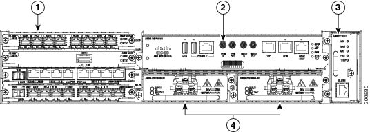
The figure below illustrates the Cisco ASR 902 Router chassis design.
|
Label |
Component |
|---|---|
|
1 |
Interface modules |
|
2 |
RSP unit |
|
3 |
Fan tray |
|
4 |
Redundant power units (two DC power units are shown) |
Overview
The Cisco ASR 902 Router expands the Cisco service provider product portfolio by providing a rich and scalable feature set of Layer 2 VPN (L2VPN) and Layer 3 VPN (L3VPN) services in a compact package. It also supports a variety of software features, including Carrier Ethernet features, Timing over Packet, and pseudowire.
The Cisco ASR 902 Router is positioned as a preaggregation router in IP Radio Access Network (RAN) (Global System for Mobile Communications (GSM), Universal Mobile Telecommunications System (UMTS), Image Maximum (iMAX), Code division multiple access (CDMA), and Long Term Evolution (LTE)) networks or an aggregation router in Carrier Ethernet networks.
Power Supply Features
The Cisco ASR 902 Router supports AC and DC power supplies. These power supplies have the following features:
-
Redundancy
The Cisco ASR 902 Router chassis includes a slot for optional redundant power supply. The redundant power supply option provides a second power supply to ensure that power to the chassis continues uninterrupted if one power supply fails or input power on one line fails. Redundancy is supported either with identical power supplies or a combination of AC and DC power supply.
-
Dying Gasp
This feature allows the router to provide an input power loss notification to the RSP so that the RSP can send appropriate SNMP traps or OAM messages and update log files on the router.
-
Status LEDs
The LEDs indicate the status of the input power and the health of the power supply.
Fan Tray Features
The fan tray has the following hardware features:
-
It provides side-to-side forced air cooling
-
It provides redundant fans
-
It is field replaceable
-
It contains status LEDs
-
It contains two alarm ports with two external alarm inputs
Dust Filter
The dust filter on the fan tray is a quadrafoam 45PPI filter that is 85 percent dust resistant. A dummy cover (A902-FAN-F-B) secures the dust filter in the chassis.
RSP Modules
The Cisco ASR 902 Router is designed to use a single RSP module to handle the data plane, network timing, and control plane functionalities for the router. The RSP configuration allows you to use Cisco IOS software to control chassis management, external management, and system status indications on the router.
RSP features include:
- Loading software onto processor-based interface modules
- Packet processing
- Traffic management, including buffering, queuing, and scheduling, Ethernet MAC functions.
- Network clocking functions, including phase and time-of-day for Building Integrated Timing Source (BITS), 1 PPS, 10 MHz, and 1588 Precision Time Protocol (PTP) clock references.
- Storage of software images, system configuration, Onboard Failure Logging (OBFL), syslog.
- PTP packet processing, including IEEE 1588-2008 for recovering network timing (frequency, phase, and time) from upstream PTP clocks for generating PTP frequency and phase references as inputs to the Synchronous Equipment Timing Source (SETS), and for distributing them to downstream PTP clocks.
- External management interfaces (RS232 console, management ENET, USB console, USB storage) and system-status LED indicators.
Supported RSP Features
The following are the RSP features supported on the Cisco ASR 902 Router:
- Centralized data plane, timing, and control plane functions for the system
- High-level control of interface modules
- Management functionalities for the router
- Control plane (host) CPU and associated memory in which Cisco IOS-XE and platform-control software run
- Nonvolatile memory for storage of software images, configurations, and system files
- Enabling and monitoring the health and presence of fan trays, interface modules, and power supplies
- Field replacement
GNSS Module (A900-CM-GNSS)
The GNSS module is present on the RSP3 modules. It is a pluggable module that allows direct interface with the external antenna.
To reduce the risk of fire, use only No. 26 AWG or larger telecommunication line cord. Statement 1023
Note | The GNSS module is not hot swappable. |
GNSS Module RF Input Requirements
- The GNSS module requires an active GPS/GNSS antenna with built-in Low-Noise Amplifier (LNA) for optimal performance. The antenna LNA amplifies the received satellite signals for two purposes:
-
Compensation of losses on the cable
-
Lifting the signal amplitude in the suitable range for the receiver frontend
The Amplification required is 22dB gain + cable/connector loss + Splitter signal loss.
The recommended range of LNA gain (LNA gain minus all cable and connector losses) at the connector of the receiver module is 22dB to 30dB with a minimum of 20dB and a maximum of 35dB.
-
-
GNSS module provides 5V to the active antenna through the same RF input.
-
Surge requirement:
-
GNSS modules have built-in ESD protections on all pins, including the RF-input pin. However, additional surge protection may be required if rooftop antennas are being connected, to meet the regulations and standards for lightning protection in the countries where the end-product is installed.
-
A lightning protection must be mounted at the place where the antenna cable enters the building. The primary lightning protection must be capable of conducting all potentially dangerous electrical energy to PE (Protective Earth).
-
Surge arrestors should support DC-pass and suitable for the GPS frequency range (1.575GHz) with low attenuation.
-
-
Antenna Sky visibility:
-
GPS signals can only be received on a direct line of sight between antenna and satellite. The antenna should see as much as possible from the total sky. For proper timing, minimum of four satellites should be locked.
Note
The antenna terminal should be earthed at the building entrance in accordance with the ANSI/NFPA 70, the National Electrical Code (NEC), in particular Section 820.93, Grounding of Outer Conductive Shield of a Coaxial Cable.
-
-
Use a passive splitter if more than one GNSS modules are fed from a single antenna.
Note | The splitter should have all the RF ports capable of DC-pass, if the antenna needs to feed power from GNSS module. |
Interface Modules
The Cisco ASR 902 Router interface modules are field-replaceable units.
Note | On RSP-1, Slot 2 Port 0 cannot be used for traffic flow on 8X1-G copper and 8X1-G SFP interface modules. |
In addition to the ports provided on an RSP, the Cisco ASR 902 Router supports the following interface modules:
Installing the Cisco ASR 902 Router
The following sections explain how to install the router and its components.
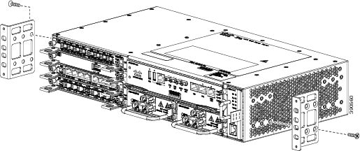
Installing the Chassis Brackets
The chassis is shipped with mounting brackets that can be installed on the front or rear of the chassis. To install the brackets on the front of the chassis, perform these steps:
Installing the Router Chassis in the Rack
Installing the Chassis Ground Connection
Before you connect the power or turn on the power to the Cisco ASR 902 Router, you must provide an adequate chassis ground (earth) connection to your router.
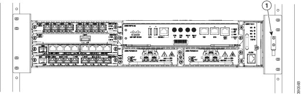
This section describes how to ground the Cisco ASR 902 Router chassis. The router provides two locations for attaching a 2-hole grounding lug according to the rack-mounting brackets you use to install the router. The Cisco ASR 902 Router supports the following rack-mounting types:
- 300-mm ETSI cabinet—Attach the grounding lug on the rack-mount bracket on the front of the router, as shown in the figure below .
To ensure that the chassis ground connection that you provide is adequate, you need the following parts and tools:
- Ratcheting torque screwdriver with Phillips head that exerts up to 15 in.-lb (1.69 N-m) of pressure for attaching the ground wire to the router
- Crimping tool as specified by the ground lug manufacturer
- 6-AWG or larger copper wire for the ground wire
- Wire-stripping tools appropriate to the wire you are using
 Caution | Before making connections to the Cisco ASR 902 Router, ensure that you disconnect the power at the circuit breaker. Otherwise, severe injury to you or damage to the router may occur. |
 Warning | This equipment must be grounded. Never defeat the ground conductor or operate the equipment in the absence of a suitably installed ground conductor. Contact the appropriate electrical inspection authority or an electrician if you are uncertain that suitable grounding is available. Statement 1024 |
Warning | Use copper conductors only. Statement 1025 |
Warning | When installing or replacing the unit, the ground connection must always be made first and disconnected last. Statement 1046 |
This unit is to be installed in a restrictive access location and must be permanently grounded to a minimum 6-AWG copper ground wire.
Perform the following procedure to ground the Cisco ASR 902 Router using a 2-hole lug and the corresponding mounting point. Most carriers require a minimum 6-AWG ground connection. Verify your carrier’s requirements for the ground connection.
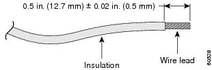
| Step 1 | If your ground wire is insulated, use a wire-stripping tool to strip the ground wire to 0.5 inch ± 0.02 inch (12.7 mm ±0.5 mm) ( the figure below ). |
| Step 2 | Slide the open end of your 2-hole ground lug over the exposed area of the ground wire. |
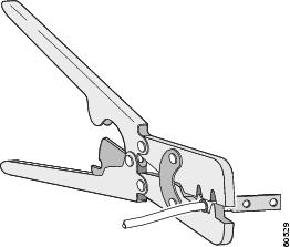
| Step 3 | Using a crimping tool (as specified by the ground lug manufacturer), crimp the ground lug to the ground wire as shown in the figure below. |
| Step 4 | Use a Phillips head screwdriver to attach the 2-hole ground lug and wire assembly to the router with the 2 pan-head Phillips head screws. For a 19-inch EIA rack, attach the 2-hole ground lug to the rear of the router. |
| Step 5 | Connect the other end of the ground wire to a suitable grounding point at your site. |
Installing the Fan Tray
The fan tray is a modular unit that provides cooling to the Cisco ASR 902 Router. Follow these steps to install the fan tray in the chassis:
| Step 1 | Orient the fan tray so that the captive screws are on the left side of the fan tray’s front panel. The figure below shows how to orient the fan tray. | ||||
| Step 2 | Guide the fan
tray into the chassis until it is fully seated.
| ||||
| Step 3 | Secure the fan
tray to the chassis using the attached captive installation screws. The
recommended maximum torque is 5.5 in.-lb (.62 N-m).
This completes the procedure for installing or replacing the fan tray in a Cisco ASR 902 Router. For information about connecting cables to the fan tray alarm port, see the Connecting the Fan Tray Alarm Port section in the Cisco ASR 902 and ASR 902U Aggregation Services Router Hardware Installation Guide. For a summary of the LEDs on the fan tray, see the LED Summary section in the Cisco ASR 902 and ASR 902U Aggregation Services Router Hardware Installation Guide. For more information about air flow guidelines, see the Air Flow Guidelinessection in the Cisco ASR 902 and ASR 902U Aggregation Services Router Hardware Installation Guide. |
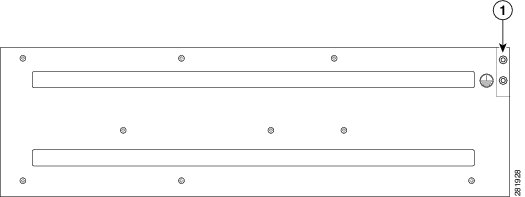
Installing the Dust Filter
| Step 1 | Remove the fan tray (if installed) from the chassis. |
| Step 2 | Remove the dummy cover from the fan tray. |
| Step 3 | Slide the dust filter onto the fan tray. |
| Step 4 | Insert the dummy cover on the fan tray to secure the filter within the chassis. |
| Step 5 | Perform the steps to install the fan tray in the chassis. See the Installing the Fan Tray section. |
RSP Installation
Follow these steps pertaining to handling an RSP module in the Cisco ASR 902 Router:
Installing an RSP Module
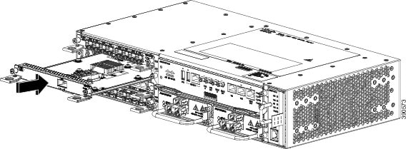
| Step 1 | Make sure that there is enough clearance to accommodate any equipment that will be connected to the ports on the module. If a blank module filler plate is installed in the slot in which you plan to install the module, remove the plate by removing its 2 Phillips pan-head screws. | ||||||
| Step 2 | Fully open both
the ejector levers on the new module, as shown in the figure below .
| ||||||
| Step 3 | Position the module in the slot. Make sure that you align the sides of the module with the guides on each side of the slot, as shown in the figure below . | ||||||
| Step 4 | Carefully slide the module into the slot until the EMI gasket on the module makes contact with the module in the adjacent slot and both the ejector levers have closed to approximately 45 degrees with respect to the module faceplate. | ||||||
| Step 5 | While pressing down, simultaneously close both the ejector levers to fully seat the module in the backplane connector. The ejector levers are fully closed when they are flush with the module faceplate. | ||||||
| Step 6 | Tighten the two
captive installation screws on the module. The recommended maximum torque is
5.5 in.-lb (.62 N-m).
| ||||||
| Step 7 | Verify that the
captive installation screws are tightened on all of the modules installed in
the chassis. This step ensures that the EMI gaskets on all the modules are
fully compressed in order to maximize the opening space for the new or
replacement module.
|
Interface Module Installation
The following sections describe the various tasks associated with interface module installation on the Cisco ASR 902 Router:
Installing an Interface Module
Note | On RSP-1, Slot 2 Port 0 cannot be used for traffic flow on 8X1-G copper and 8X1-G SFP interface modules. |
| Step 1 | Before inserting an interface module, make sure that the chassis is grounded. | ||||||
| Step 2 | To insert the interface module, carefully align the edges of the interface module between the upper and lower edges of the router slot. | ||||||
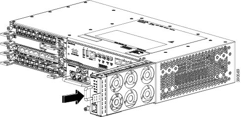
| Step 3 | Carefully slide the interface module into the router slot until the interface module makes contact with the backplane. The figure below shows how to install the interface module. | ||||||
| Step 4 | Tighten the locking thumbscrews on both sides of the interface module. The recommended maximum torque is 5.5 in.-lb (.62 N-m). | ||||||
| Step 5 | Connect all the cables to each interface module.
|
Installing a DC Power Supply
Note | This equipment is suitable for installation in Network Telecommunications Facilities and locations where the NEC applies. The equipment is suitable for installation as part of the Common Bonding Network (CBN). |
Caution | The grounding architecture of this product is DC-isolated (DC-I) for DC-powered products. DC-powered products have a nominal operating DC voltage of 48 VDC. Minimal steady state DC operating voltage is 19.2 VDC. |
Installing a DC Power Supply Module
| Step 1 | Ensure that the system (earth) ground connection has been made. For ground connection installation instructions, see the Installing the Chassis Ground Connection. |
| Step 2 | If present, remove the blank power supply filler plate from the chassis power supply bay opening by loosening the captive installation screws. |
| Step 3 | Verify that power to the DC circuit connected to the power supply you are installing is off. To ensure that power has been removed from the DC circuits, locate the circuit breakers for the DC circuits, switch the circuit breakers to the OFF position, and tape the circuit-breaker switches in the OFF position. |
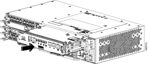
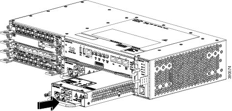
| Step 4 | Grasp the power supply handle with one hand. Place your other hand underneath the power supply, as shown in the figure below . Slide the power supply into the power supply bay. Make sure that the power supply is fully seated in the bay. |
| Step 5 | Tighten the
captive installation screws of the power supply. The recommended maximum torque
is 5.5 in.-lb (.62 N-m).
If you are installing a redundant DC power supply, repeat these steps for the second power source too. |
Activating a DC Power Supply
| Step 1 | Remove the tape from the circuit-breaker switch handle, and restore power by moving the circuit-breaker switch handle to the On (|) position. |
| Step 2 | Verify power
supply operation by checking if the power supply front panel LEDs are in the
following states:
If the LEDs indicate a power problem, see Troubleshooting section in the Cisco ASR 902 and ASR 902U Aggregation Services Router Hardware Installation Guide. If you are installing a redundant DC power supply, ensure that each power supply is connected to a separate power source in order to prevent power loss in the event of a power failure. If you are installing a redundant DC power supply, repeat these steps for the second power source. |
Installing an AC Power Supply Module
| Step 1 | Ensure that the system (earth) ground connection has been made. For ground connection installation instructions, see the Installing the Chassis Ground Connection section. | ||
| Step 2 | If necessary, remove the blank power supply filler plate from the chassis power supply bay opening, by loosening the captive installation screws. | ||
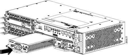
| Step 3 | Grasp the power supply handle with one hand. Place your other hand underneath the power supply, as shown in the figure below . Slide the power supply into the power supply bay. Make sure that the power supply is fully seated in the bay. | ||
| Step 4 | Tighten the
captive installation screws of the power supply. The recommended maximum torque
is 5.5 in.-lb (.62 N-m).
|
Connecting a Cisco ASR 902 Router to the Network
Note | When installing the cables to the RSPs, we recommend that you leave a service loop of extra cabling for fan tray removal. |
The following sections describe how to connect a Cisco ASR 902 Router to the network:
Connecting Console Cables
The following sections describe how to connect to the Cisco ASR 902 Router using console cables:
Connecting to the USB Serial Port Using Microsoft Windows
This procedure shows how to connect to the USB serial port using Microsoft Windows.
Note | Install the USB device driver before establishing a physical connection between the router and the PC, by using the USB console cable plugged into the USB serial port. Otherwise, the connection will fail. For more information, see the Installing the Cisco USB Device Driver. |
| Step 1 | Connect the end
of the console cable with the RJ45 connector to the light blue console port on
the router.
or Connect a USB Type A-to-Type A cable to the USB console port, as shown in the figure below. If you are using the USB serial port for the first time on a Windows-based PC, install the USB driver now according to the instructions in the following sections:
| ||||
| Step 2 | Connect the end of the cable with the DB-9 connector (or USB Type-A) to the terminal or PC. If your terminal or PC has a console port that does not accommodate a DB-9 connector, you must provide an appropriate adapter for that port. | ||||
| Step 3 | To communicate with the router, start a terminal emulator application, such as Microsoft Windows HyperTerminal. This software should be configured with the following parameters: |

Powering Up the Cisco Router
Make certain that all card slots and compartments are closed off. Install blank faceplates on any empty slots. Always have power supply slots filled. If you leave a power supply slot uncovered, then you risk exposure to hazardous voltages on the power pins on the midplane.
Warning | Blank faceplates and cover panels serve three important functions: they prevent exposure to hazardous voltages and currents inside the chassis; they contain electromagnetic interference (EMI) that might disrupt other equipment; and they direct the flow of cooling air through the chassis. Do not operate the system unless all cards, faceplates, front covers, and rear covers are in place. Statement 1029 |
After installing your Cisco Router and connecting cables, start the router and follow these steps:
| Step 1 | Activate the DC
power supply using the steps described in
Activating
the DC Power Supply.
| ||||
| Step 2 | Observe the
initialization process. When the system boot is complete (the process takes a
few seconds), the Cisco Router RSP begins to initialize.
Example: Loading the Default System Boot Image
Current image running: Boot ROM0
Last reset cause: PowerOn
UEA platform with 2097152 Kbytes of main memory

rommon 1 > boot
Located asr902.bin
Image size 240888408 inode num 13, bks cnt 58811 blk size 8*512
##############################################################################################################
Boot image size = 240888408 (0xe5baa58) bytes

Package header rev 0 structure detected
Calculating SHA-1 hash...done
validate_package: SHA-1 hash:
calculated fe76800b:4343b84e:3861a949:368a3710:134383bc
expected fe76800b:4343b84e:3861a949:368a3710:134383bc
Image validated
Passing control to the main image..

Restricted Rights Legend

Use, duplication, or disclosure by the Government is
subject to restrictions as set forth in subparagraph
(c) of the Commercial Computer Software - Restricted
Rights clause at FAR sec. 52.227-19 and subparagraph
(c) (1) (ii) of the Rights in Technical Data and Computer
Software clause at DFARS sec. 252.227-7013.

cisco Systems, Inc.
170 West Tasman Drive
San Jose, California 95134-1706

Router#show version
Cisco IOS XE Software, Cisco IOS Software, ASR903 Software PPC_LINUX_IOSD-UNIVERSALK9_NPE-M), Version 15.4
Copyright (c) 1986-2014 by Cisco Systems, Inc.
Compiled Sun 05-Jan-14 20:59 by mcpre


Cisco IOS-XE software, Copyright (c) 2005-2014 by cisco Systems, Inc.
All rights reserved. Certain components of Cisco IOS-XE software are
licensed under the GNU General Public License ("GPL") Version 2.0. The
software code licensed under GPL Version 2.0 is free software that comes
with ABSOLUTELY NO WARRANTY. You can redistribute and/or modify such
GPL code under the terms of GPL Version 2.0. For more details, see the
documentation or "License Notice" file accompanying the IOS-XE software,
or the applicable URL provided on the flyer accompanying the IOS-XE
software.


ROM: IOS-XE ROMMON

Router uptime is 2 minutes
Uptime for this control processor is 5 minutes
System image file is "bootflash:/asr902.bin"
Last reload reason: PowerOn
This product contains cryptographic features and is subject to United
States and local country laws governing import, export, transfer and
use. Delivery of Cisco cryptographic products does not imply
third-party authority to import, export, distribute or use encryption.
Importers, exporters, distributors and users are responsible for
compliance with U.S. and local country laws. By using this product you
agree to comply with applicable laws and regulations. If you are unable
to comply with U.S. and local laws, return this product immediately.
A summary of U.S. laws governing Cisco cryptographic products may be found at:
http://www.cisco.com/wwl/export/crypto/tool/stqrg.html
If you require further assistance please contact us by sending email to
export@cisco.com.
License Level: metroservices
License Type: Default. No valid license found.
Next reload license Level: metroservices
cisco ASR-902 (RSP1) processor with 425945K/6147K bytes of memory.
Processor board ID
31 Gigabit Ethernet interfaces
32768K bytes of non-volatile configuration memory.
2097152K bytes of physical memory.
1328927K bytes of SD flash at bootflash:.
Configuration register is 0x2102
Router#
During the boot process, observe the system LEDs. The LEDs on the shared port adapter go on and off in an irregular sequence. Once the router has booted, the green STATUS LED comes on and stays on. |
Verifying the Front Panel LEDs
The front-panel indicator LEDs provide power, activity, and status information useful during bootup. For more detailed information about the LEDs, see Troubleshooting in the Cisco ASR 902 and ASR 902U Aggregation Services Router Hardware Installation Guide.
Verifying the Hardware Configuration
To display and verify the hardware features, enter the following commands:
Checking Hardware and Software Compatibility
To check the minimum software requirements of the Cisco IOS software with the hardware installed on your Cisco Router, Cisco maintains the Software Research tool on Cisco.com. The tool provides the minimum Cisco IOS requirements for individual hardware modules and components.
Note | To access this tool, you must have a Cisco.com login account. |
Configuring the Cisco Router at Startup
This section explains how to create a basic running configuration for your Cisco Router.
Note | You need to acquire the correct network addresses from your system administrator or consult your network plan to determine correct addresses before you can complete the router configuration. |
Before continuing the configuration process, check the current state of the router by entering the show version command. The show version command displays the release of Cisco IOS software that is available on the router.
For information on modifying the configuration after you create it, see the Cisco IOS configuration and command reference guides.
To configure a Cisco Router from the console, you must connect a terminal or terminal server to the console port on the Cisco Router RSP. To configure the Cisco Router using the management Ethernet port, you must have the router’s IP address available.
Accessing the CLI Using the Console
| Step 1 | When your
system is booting, type No at the prompt.
Example:
         --- System Configuration Dialog ---
Would you like to enter the initial configuration dialog? [yes/no]: no
|
| Step 2 | Press Return to
enter user EXEC mode. The following prompt appears:
Router> |
| Step 3 | From the user
EXEC mode, enter the enable command as shown in the following example:
Router> enable |
| Step 4 | At the password
prompt, enter your system password, as shown in the following example. If an
enable password has not been set on your system, this step may be skipped.
Password: enablepass When your enable password is accepted, the privileged EXEC mode prompt is displayed: Router# You now have access to the CLI in privileged EXEC mode and you can enter the necessary commands to complete your desired tasks. |
| Step 5 | To exit the
console session, enter the quit command as shown in the following example:
Example: Router# quit |
Configuring Global Parameters
When you first start the setup program, you must configure the global parameters. These parameters are used for controlling system-wide settings. Perform the following steps to enter the global parameters:
| Step 1 | Connect a
console terminal to the console port, and then boot the router. For more
information on connecting a console terminal, see
Connecting Console Cables
section.
When you see this information, it means that you have successfully booted your router: Example: Restricted Rights Legend Use, duplication, or disclosure by the Government is subject to restrictions as set forth in subparagraph (c) of the Commercial Computer Software - Restricted Rights clause at FAR sec. 52.227-19 and subparagraph (c) (1) (ii) of the Rights in Technical Data and Computer Software clause at DFARS sec. 252.227-7013. cisco Systems, Inc. 170 West Tasman Drive San Jose, California 95134-1706 . . . --- System Configuration Dialog --- Would you like to enter the initial configuration dialog? [yes/no]: yes Press RETURN to get started! | ||
| Step 2 | The first
sections of the configuration script appear only at an initial system startup.
On subsequent uses of the setup facility, the script begins with a System
Configuration Dialog as shown below: When you are prompted about whether you
want to enter the initial configuration dialog, enter yes.
Example: Would you like to enter the initial configuration dialog? [yes/no] yes At any point you may enter a question mark '?' for help. Use ctrl-c to abort configuration dialog at any prompt. Default settings are in square brackets '[]'. Basic management setup configures only enough connectivity for management of the system, extended setup will ask you to configure each interface on the system. Basic management setup configures enough connectivity for managing the system; extended setup will ask you to configure each interface on the system. For detailed information about setting global parameters, refer to the Cisco ASR 900 Series Router Software Configuration Guide. |
Checking the Running Configuration Settings
To check the value of the settings you have entered, enter the show running-config command at the Router# prompt:
Router# show running-config
To review changes you make to the configuration, use the EXEC mode show startup-config command to see the changes and copy run-start stored in NVRAM.
Saving the Running Configuration to NVRAM
To store the configuration or changes to your startup configuration in NVRAM, enter the copy running-config startup-config command at the Router# prompt:
Router# copy running-config startup-config
Using this command saves the configuration settings that you created in the router using configuration mode and the setup facility. If you fail to do this, your configuration will be lost the next time you reload the router.
Safely Powering Off the Cisco Router
This section explains how to shut down the Cisco Router. It is recommended that before turning off all power to the chassis, you issue the reload command. This insures that the operating system cleans up all the file systems. Once the reload operation is complete, then the Cisco Router can be powered off safely.
To remove power from the Cisco Router safely, follow this procedure and see the examples:
| Step 1 | Slip on the ESD-preventive wrist strap that was included in the accessory kit. |
| Step 2 | Enter the reload command. |
| Step 3 | Confirm the
reload command.
Example: Router# reload Proceed with reload? [confirm] *Sep 7 09:00:40.084 IST:%SYS-5-RELOAD: Reload requested by console. Reload Reason: Reload Command. Aug 17 00:06:47.051 R0/0: %PMAN-5-EXITACTION: Process manager is exiting: prs exit with reload chassis code |
| Step 4 | After
confirming the reload command, wait until the system bootstrap message displays
before powering off the system.
Example: System Bootstrap, Version 15.3(1r)S1, RELEASE SOFTWARE (fc1) Technical Support: http://www.cisco.com/techsupport Copyright (c) 2012 by cisco Systems, Inc. Current image running: Boot ROM0 Last reset cause: RSP-Board UEA platform with 2097152 Kbytes of main memory |
| Step 5 | Remove any
power cables from the Cisco Router.
|
Related Documents
-
Cisco ASR 902 and ASR 902U Aggregation Services Router Hardware Installation Guide can be viewed at: https://www.cisco.com/c/en/us/td/docs/routers/asr902/hardware/guide/b-asr902-hig.html
-
The documentation for the supported software features can be viewed at https://www.cisco.com/c/en/us/support/routers/asr-903-series-aggregation-services-routers/products-installation-and-configuration-guides-list.html.
Copyright © 2017-2018, Cisco Systems, Inc. All rights reserved.