Contents
- Autonomic Networking
- Finding Feature Information
- Restrictions for Autonomic Networking
- An Introduction to Autonomic Networking
- The Vision of Autonomic Networking
- Autonomic Networking Infrastructure
- Deploying Autonomic Networking
- Device Support
- Deployment Considerations
- Setup an External Certificate Authority
- Configuring the Certificate Authority
- Configuring Crypto PKI RA Mode Server Configuration in Registrar
- Granting RA mode CS Certificate from IOS CA server
- Setup of the Registrar
- Enabling Autonomic Networking on the Registrar Device
- Configuring the Autonomic Registrar
- Updating the Whitelist
- Registrar Redundancy
- Enrolling Network Devices
- Enrolling a Device
- Discovering Layer 2 Channels
- Limiting the VLAN Range Using Intent
- Configuring the Intent
- Validating the Network
- Verifying Reachability
- Enabling NOC Services
- Generic NOC Setup
- Server Setup
- Verifying Reachability to Autonomic Networking Devices from External Non-Autonomic Network
- Announcing Services
- Syslog
- SSH Into a Remote Device
- Configuration Download
- Additional Tasks
- By-Passing Non Autonomic Devices
- Backing Up Registrar
- Troubleshooting Autonomic Networking
- Verify Status of the Registrar
- Verify Whether a Device Received Domain Certificate
- Verify Enrolled Devices Details
- Verifying quarantined devices
- Verify Channel Discovery
- Verify Neighbor Discovery
- Verify Autonomic Control Plane
- Verify Autonomic Service Discovery
- Verify the configured intent
- Verify the Status of the Autonomic Interfaces
- Clear Commands
- AN Syslog messages explained
- Resetting Autonomic Functions and Devices
- Debug Commands
- Additional References for Autonomic networking
- Feature Information for Autonomic Networking
First Published:
Last Updated:
Text Part Number:
Autonomic
Networking
Autonomic Networking makes network devices intelligent by introducing self-management concepts that simplify network management for the network operator.
Finding Feature Information
Your software release may not support all the features documented in this module. For the latest caveats and feature information, see Bug Search Tool and the release notes for your platform and software release. To find information about the features documented in this module, and to see a list of the releases in which each feature is supported, see the feature information table.
Use Cisco Feature Navigator to find information about platform support and Cisco software image support. To access Cisco Feature Navigator, go to www.cisco.com/go/cfn. An account on Cisco.com is not required.
Restrictions for Autonomic Networking
-
Autonomic Networking Channel Discovery is supported on physical Ethernet interfaces only.
-
Autonomic Networking feature is available on crypto (K9) images only.
-
Devices running on Cisco IOS 15.6(2)S, 15.6(02)T, 16.2.1 and later releases are not compatible with the earlier releases. To make it compatible, the administrator must configure autonomic adjacency-discovery on the interface.
-
Autonomic Networking, Open Plug-n-Play (OPP), and Zero Touch Provisioning (ZTP) are different zero touch solutions. It is not recommended to use autonomic networking and other zero touch solutions at the same time.
An Introduction to Autonomic Networking
The Vision of Autonomic Networking
The final goal of Autonomic Networking is self-management. Devices are not configured in the traditional way, but self-configured; through discovery and negotiation with other autonomic nodes in the network. After self-configuration, autonomic nodes also self-protect against security threats, self-optimize to adapt to new situations, and self-heal in case of issues. RFC 7575 (http://tools.ietf.org/html/rfc7575): Autonomic Networking: Definitions and Design Goals describes the fundamental ideas in detail.
An important aspect of Autonomic Networking is security. If devices discover and negotiate directly between themselves, then a strong security infrastructure is required, to secure these communications. Therefore, an autonomic network must be secure by default. Refer to the position paper Making the Internet Secure by Default ( https://tools.ietf.org/html/draft-behringer-default-secure-00) for more details.
-
The Autonomic Networking Infrastructure (ANI), which provides a self-managing security hierarchy Public Key Infrastructure (PKI), secure communication channels, and discovery functions.
-
Autonomic functions, which utilize the ANI to communicate and self-manage parts of the functions of autonomic devices. To ensure interoperability with existing hardware, less secure modes of initial provisioning are supported.
The ANI is available for use, and the set up is described in this document. Autonomic functions are not yet supported.
Autonomic Networking Infrastructure
-
A security infrastructure in the form of a self-managing Public Key Infrastructure (PKI). Every autonomic node enrols with a Certificate Authority, to receive a domain certificate. This domain certificate is then used to secure all subsequent operations.
-
A secure communications infrastructure; the Autonomic Control Plane (ACP).
-
Service discovery functions for nodes to discover services such as AAA or TFTP, without the need for configuration.
 Note | An autonomic network element can securely and automatically join its network, removing the need for pre-staging. To ensure interoperability with existing hardware new devices are initially identified using their unsecured Unique Device Identifier (UDI). This means that an attacker knowing a valid UDI can today fake a valid device, and/or carry out a man-in-the-middle attack. This Trust On First Use policy will be replaced on equipment that supports Secure UDI (SUDI) with a stricter policy. After initial deployment all ongoing operations are equally secured. |
-
The ACP can be used as a virtual out-of-band channel. It is independent of the configuration of the devices. Therefore, an incorrect configuration or no configuration at all, does not impact its use. This way, controllers, or the administrator via SSH can access all devices reliably, even in the presence of incorrect configurations. This removes the need for a real out of band network, or the need for engineers to be physically on site for troubleshooting.
-
A secure, zero-touch device enrolment; an autonomic network element can securely and automatically join its network, removing the need for pre-staging.
This document describes how to set up the ANI.
Background Information
Autonomic Networking is currently being standardized in the IETF. For more information, refer to the ANIMA WG: http://tools.ietf.org/wg/anima/
The fundamental concepts of Autonomic Networking are published as RFC 7575 (http://tools.ietf.org/html/rfc7575): Autonomic Networking: Definitions and Design Goals
For more information about ACP, refer to RIPE: https://ripe70.ripe.net/presentations/49-A-Virtual-Out-Of-Band-Channel-RIPE-70.pdf
For videos, see Videos on Demand: https://ripe70.ripe.net/archives/video/17
Deploying Autonomic Networking
Device Support
|
Platform |
Introduced in release |
Registrar functionality supported |
Image required |
|---|---|---|---|
|
ASR-901 |
15.3(3)S |
Yes |
asr901-universalk9-mz |
|
ME-3600X-24CX-M |
15.4(2)S |
Yes |
me360x_t-universalk9-mz |
|
ME-3600X-24TS-M |
15.4(2)S |
Yes |
me360x-universalk9-mz |
|
ME-3800X-24FS-M |
15.4(2)S |
Yes |
me380x-universalk9-mz |
|
ASR903/902 |
15.4(2)S |
Yes |
asr903rsp2-universalk9_npe asr903rsp1-universalk9_npe |
|
ASR920 |
15.5(1)S |
Yes |
asr920-universalk9_npe |
|
CSR1000v |
15.5(2)S |
Yes |
csr1000v-universalk9 |
|
C892FSP-K9 |
15.6(1)T |
Yes |
c800-universalk9-mz |
|
ASR 1000 series |
16.2(1) |
Yes |
|
|
ISR 4000 series |
16.2(1) |
Yes |
|
|
WS-C3650 |
16.3(1) |
No |
|
|
WS-C3850 |
16.3(1) |
No |
|
Deployment Considerations
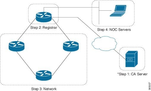
A registrar decides as to which devices can join the autonomic network. It validates that a new device is part of the domain, and if so, it forwards a certificate signing request for that device to the CA. This bootstraps the device, which means that the device obtains a cryptographically verifiable domain and device identity, such as router2.example.com, with a corresponding domain certificate, signed by a CA.
A registrar also contains an IOS CA. You can leverage either on this local CA on the registrar, or an external one. External CA server is strongly recommended for production environment. The local CA on the registrar can be used for lab trials.
Each autonomic domain must have one single CA (the root or trust anchor of the domain), but it can have one or several registrars. If you are planning to use local CA you can skip step 1.
Setup an External Certificate Authority
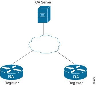
The figure above shows an external CA and RA deployment with multiple registrars. External CA can be on an IPV6 or IPV4 network. If multiple registrars are used in a domain, all registrars must point to the same CA. Any standard CA server which supports Simple Certificate Enrollment Protocol (SCEP) can be used.
Configuring the Certificate Authority
This section explains the configuration of a Cisco IOS based CA. A non-IOS external CA is possible, but the configuration is out of scope of this document.
enable
configure terminal
ip http server
crypto pki server ANRA-CS
database level complete
database archive pem password mypassword
grant auto
no shutdown
The no shutdown command leads to automatic generation of key pair.
Note | The recommended lifetime for a CA certificate is three years and device certificate is one year. This is the default lifetime provided by Cisco IOS based CA. It is strongly recommended to sync the clock of the device to the authentic clock, before configuring it as Certificate Authority. |
If the database-url option is not configured, PKI files are saved to nvram by default. It is recommended to configure database-url with flash:/bootflash:/harddisk: option.
Verifying status of the Certificate Authority server
You will know that the CA server configuration is successful, when you see the server status and state as enabled in the output of show crypto pki server certificate-server-name command. If not, refer Public Key Infrastructure Configuration Guide for troubleshooting the issue.
Device# show crypto pki server ANRA-CS
Certificate Server ANRA-CS:
Status: enabled
State: enabled
Server's configuration is locked  (enter "shut" to unlock it)
Issuer name: CN=ANRA-CS
CA cert fingerprint: 8E16D0C0 BED94E38 028DA09E FB2CDAB1
Granting mode is: auto
Last certificate issued serial number (hex): 1
CA certificate expiration timer: 11:43:06 IST Sep 15 2018
CRL NextUpdate timer: 17:43:11 IST Sep 16 2015
Current primary storage dir: nvram:
Database Level: Complete - all issued certs written as <serialnum>.cer
Configuring Crypto PKI RA Mode Server Configuration in Registrar
Each Registrar must have an RA configured. In case of external-CA scenario, each Registrar must be configured as crypto PKI RA mode server before configuring Autonomic Registrar configuration. Make sure the clock of the Registrar and CA should be the same before configuring crypto PKI RA mode server configuration.
ip http server
crypto pki trustpoint ANRA-CS
enrollment url http://10.1.1.1:80
subject-name cn=ioscs RA
crypto pki server ANRA-CS
issuer-name cn=ioscs RA
database archive pem password mypassword
database url flash:
mode ra
grant auto
no shutdown

!After executing “no shutdown” user will be prompted with following questions
% Do you accept this certificate? [yes/no]: yes
Password:
Re-enter password:
% Include the router serial number in the subject name? [yes/no]: yes
% Include an IP address in the subject name? [no]:
Request certificate from CA? [yes/no]: yes
Note | Subject-name must be cn=ioscs RA, when using IOS CA server. Certificate-server-name and trustpoint-name must be ANRA-CS. mode ra transparent must be configured under crypto pki server ANRA-CS, if the external CA is Microsoft CA server. |
When using external CA, the Registrar needs to be configured as crypto RA mode server.
Note | It is strongly recommended to sync the clock of the Registrar device to an authentic clock, before configuring it as crypto PKI RA mode server. |
Granting RA mode CS Certificate from IOS CA server
The Registrar (configured as Crypto PKI RA mode server) will request a RA mode CS certificate from the CA server. In case of IOS CA server, complete the following steps to grand the RA mode CS certificate from CA server.
-
Check the pending RA certificate request on the CA server. Note the request ID.
show crypto pki server certificate-server-name requests
Device# show crypto pki server ANRA-CS requests Enrollment Request Database: Subordinate CA certificate requests: ReqID State Fingerprint SubjectName -------------------------------------------------------------- RA certificate requests: ReqID State Fingerprint SubjectName -------------------------------------------------------------- 1 pending E5FE1C4B2CA5155C6FA97ECD50065F8A serialNumber=CAT1702U14Y+hostname=Router,cn=ioscs RA Router certificates requests: ReqID State Fingerprint SubjectName -------------------------------------------------------------- -
Grant the RA certificate by executing the crypto pki server certificate-server-name grant [request ID|all] on the CA server.
Device#crypto pki server ANRA-CS grant 1
Verify RA certificate status on the RA
The RA configuration and obtaining RA and CA certificates is successful if you see status of the RA and CA certificate as Available in the output of the show crypto pki certificates command. If not, refer Public Key Infrastructure Configuration Guide for troubleshooting the issue.
Device#show crypto pki certificates
Certificate (RA mode CS certificate)
  Status: Available
  Certificate Serial Number (hex): 02
  Certificate Usage: General Purpose
  Issuer:
    cn=ANRA-CS
  Subject:
    Name: Router
Setup of the Registrar
The registrar is a logical function on an autonomic device. Therefore, you have to enable a device first as an autonomic device, then configure the registrar function.
Note | It is strongly recommended to synchronize the device clock with the authentic clock before configuring the autonomic registrar configuration. It is also recommended to configure the registrar as NTP master with higher stratum, for example, stratum 8, before configuring the registrar. |
Enabling Autonomic Networking on the Registrar Device
Enable autonomic networking on the registrar by executing the following commands:
enable
configure terminal
autonomic
Verifying the status of autonomic
After enabling autonomic use the show autonomic device command to verify the status. This command shows the Unique Device Identifier (UDI) of the device.
Device#show autonomic device

        UDI                            PID:A901-12C-FT-D SN:CAT1602U0C3
        Domain Cert is Not Valid
At this point, the registrar function is not active yet, therefore the device does not received a domain certificate. This is why the Domain Cert is Not Valid message is displayed here.
Configuring the Autonomic Registrar
Domain-id and CA configurations are mandatory configurations for a registrar. Although, whitelist is optional, it is recommended to have whitelist configured for deployments.
Note | The Domain-id here represents an autonomic domain and is independent of the DNS system. |
A whitelist is a file containing a list of UDIs of the devices that are allowed to join the autonomic domain. This prevents unauthorized device from joining the domain. When a whitelist is configured, only those devices present in the whitelist will be accepted. If whitelist is not configured, registrar allows all devices into the domain. Whitelist files can be created on a Linus or Unix server and then copied over to the registrar using TFTP.
enable
configure terminal
autonomic registrar
domain-id abc.com
whitelist flash:whitelist.txt
database-url flash:
CA local
no shut
The following is an example for configuring the autonomic registrar with external CA server:
enable
configure terminal
autonomic registrar
domain-id abc.com
whitelist flash:whitelist.txt
database-url flash:
CA url http://10.1.1.1:80
no shut
Note | Before modifying any registrar parameters the registrar needs to be shut. After the change, the no shut command should be run. Also, if the whitelist is modified, the registrar must be first shut and then the no shut command should be run. The domain name cannot be modified after the registrar goes live. |
If you unconfigure the registrar, the accepted device database of the registrar ANR_ACC.an will be removed. If you are planning to re-deploy the registrar, make sure that you backup the registrar as mentioned in the section Backing up Registrar.
If database-url is not configured, autonomic networking files will be saved to nvram by default. It is recommended to configure database-url with flash:/bootflash:/harddisk: option.
Note | It is strongly recommended to backup the autonomic networking accepted database file (ANR_ACC.an) and whitelist file periodically. These files are required in case of re-deployment of Autonomic Registrar due to RMA etc. |
Verifying status of registrar
After configuring no shut on the registrar, verify whether the status of the registrar is Autonomic Registrar Live. Also, the domain id should show the configured domain name. If not, refer the Troubleshooting section. Use the show autonomic registrar command to check the status.
Device#show autonomic registrar

Domain ID abc.com
Whitelist bootflash:udi_list.txt
Database URL bootflash:
Status Autonomic Registrar Live
Address FD3C:C122:4DCD:0:C8F9:F98D:4B80:1
Certificate (sub:) cn=ANRA-CS
Verify whether registrar device received a domain certificate
The registrar is a logical function on an autonomic device. In the earlier section, we described how to configure the registrar function. Once this is enabled, the device itself must bootstrap. Run the show autonomic device to verify the status. The output should show the configured domain name and should show domain certificate as Valid. It should also show the domain certificate details and the device address. If not, refer the troubleshooting section.
Device#show autonomic device

Status Enabled
Type Autonomic Registrar
UDI PID:ASR-903 SN:FOX1611P3UR
Device ID c8f9.f98d.4b80-1
Domain ID abc.com
Domain Certificate (sub:) ou=abc.com+serialNumber=PID:ASR-903 SN:FOX1611P3UR,cn=c8f9.f98d.4b80-1
Certificate Serial Number 02
Device Address FD3C:C122:4DCD:0:C8F9:F98D:4B80:1
Domain Cert is Valid
Updating the Whitelist
Note | The revoke and renew featue of the certificate is supported only in deployments with external CA server. |
Note | To allow a quarantined device, the device-accept udi command under registrar could be used. This is not recommended. |
Registrar Redundancy
Multiple registrars are supported in case of external CA deployment. CA for each registrar should be same and the devices getting enrolled by any of these registrars can establish ACP between each other.
Note | Devices enrolled by different registrars can establish ACP between them if they are anchored to the same root CA even if they have different domain-ids (that is, enrolled by registrars with different domain-ids configured but same external CA). |
Enrolling Network Devices
Enrolling a Device
Devices need to be enrolled into an autonomic domain. This is the process of receiving domain parameters and a domain certificate. If a device is successfully enrolled, the message domain cert is valid is displayed, at the end of the output of the show autonomic device command.
You can enroll devices into a domain with the help of a neighboring proxy (which could be the registrar or any other enrolled autonomic node). The protocol for discovering neighboring devices is called Adjacency Discovery (AD). This uses link local IP packets. Therefore, a device attempting enrolment must have a neighbor on one of its links, that is already enrolled in a domain.
Case 1: A device without start-up configuration (greenfield)
-
If the device receives a channel discovery packet, it enrolls into a domain and receives a domain certificate. The device is then goes into the AN active mode.
-
If the device is configured on the console or auxiliary port, the autonomic networking process will shut down. The device then goes into the AN off mode.
If you have access to the console of a device, while booting up, if the device enters the system configuration dialog, do not type anything at the prompt. If you type Yes or No at the prompt, autonomic networking will be disabled. You can re-enable autonomic networking after the device boots up.
To enable autonomic networking, configure the autonomic command in global configuration mode.
When the system configuration dialog is aborted, following are the differences between devices with respect to the system configuration dialog and the behavior of autonomic networking:
-
These devices have system configuration dialog and autonomic networking waits for channel discovery at the system configuration dialog.
-
Autonomic networking will be in passive mode. If you enter Yes or No, autonomic networking will get aborted.
-
Upon receiving channel discovery, autonomic discovery mode changes to active; and aborts the system configuration dialog, and configures the autonomic command in running configuration.
-
This device does not have system configuration dialog.
-
Autonomic networking will be in passive mode even if you enter ECEC mode commands like the show command. If you go into the configuration mode, autonomic networking will get aborted.
-
These devices have system configuration dialog, and interfaces will remain down if these devices are in the system configuration dialog. At this point, if you enter Yes or No, autonomic networking will get aborted.
-
After a wait period of five minutes, autonomic networking aborts the system configuration dialog; and remains passive even if you enter EXEC commands like the show command.
-
If you go into the configuration mode, autonomic networking gets aborted.
Case 2: A device with start-up configuration (brownfield)
If a device has a start-up configuration, the configuration determines whether the device must run in autonomic networking mode or not. By default, autonomic networking is not enabled on a device with start-up configuration. To enable autonomic networking (and thus to allow it to bootstrap into a domain), enter the autonomic command in the global configuration mode. To disable autonomic networking and (if applicable) delete all autonomic networking state on the device, enter the no autonomic command in global configuration mode.
Observing Device Enrolment on a Registrar
You can follow a device enrollment process on the registrar. Following are the syslog messages that indicate successful enrollment of the new device. If you do not see these messages, see the Troubleshooting section.
%AN-5-DEVICE_BOOTSTRAPPED_BY_ANR: Device with UDI (<UDI>) and (Addr <Device Address>) has been boot strapped by autonomic registrar, in autonomic domain <domain-id>
%AN-6-DEVICE_ALLOWED_BY_ANR: Device with UDI (<UDI>) connected to Proxy (Addr <Device Address>) on the interface <Physical interface of proxy> is allowed by Autonomic registrar (Addr <Device Address of Registrar>) in its domain <domain-id> and has been assigned IP Addr (<Device Address assigned to new device>) and Device ID (<Device-id assigned to new device>)
Example
%AN-5-DEVICE_BOOTSTRAPPED_BY_ANR: Device with UDI (PID:ISR4451-X/K9 SN:FGL19231046) and (Addr FD57:4317:43D7:0:64F6:9D35:DAB0:2) has been boot strapped by autonomic registrar, in autonomic domain an-cisco.com
%AN-6-DEVICE_ALLOWED_BY_ANR: Device with UDI (PID:ISR4451-X/K9 SN:FGL19231046) connected to Proxy (Addr FD57:4317:43D7:0:64F6:9D35:DAB0:1) on the interface GigabitEthernet0/0/0 is allowed by Autonomic registrar (Addr FD57:4317:43D7:0:64F6:9D35:DAB0:1) in its domain an-cisco.com and has been assigned IP Addr (FD57:4317:43D7:0:64F6:9D35:DAB0:2) and Device ID (64f6.9d35.dab0-2)
Enrollment can also be verified using the show autonomic registrar devices accepted detail command on the registrar. This command displays the UDI of the enrolled device, device ID, IPv6 address and key data. If the expected device is not present in this output, see the Troubleshooting section.
Device# show autonomic registrar devices accepted detail

UDI: "PID:A901-12C-FT-D SN:CAT1702U14Y"
        Device ID:                     0006.f6ac.3be0-1
        Address:                       FD08:2EEF:C2EE:0:6:F6AC:3BE0:1
        Key Len:                       422
        Key data:                     308201A2300D06092A864886F70D01010105000382018F003082018A0282018100C2ECDD51CC34B1DABC8B910AF9433178EB9B406DDE22D03CF2D319D587E88E34F63F4ED6944EFCED1801F24D1DF3D25B8ECAE8D397CE5DCCFAABB9FE647BEE0C6E39007B92662963463EE5628397B19F52B90B2AE0560596047F8B257D32D4352E749E40CD2F0A24188C6D3B74B3CD90709FA92CB04DC78687CCBBCC2B0698108143B04447C5962AECBA5F12632DA9E45EE9B131B9139C0C09F31E34E08AECD624330BC3D82E1BAF3149364C9E829E2A7E0A75FBED5B0BBC65D31291CF2B6CD2E1795F713E5FAFC769BAFC7CD658C202A5E6527BAF2F4C45BA42C585A43E8D5E7646F383713D63A1023E4B1526D97704126E2B6724A70C4166FD6E4567983E56E4F4D1D93B63CF8EBD50D7EFC0A66CF3F1653C4EE706813E9C29A084CA8DC3B5E529859C60ECAC5441694CEF77A63DF1D1F4B452399F6D30E4F6100A47B8615A4D4C2FF210575E7E7889A3941BE5B8143230A4FD9E803A06998AEA0EFEB447A999F7FAD3B9E5D93AD4BDCDCDA50BB1B71AB009FEA6D9115165D2CB3FA0FB496F0203010001
Note | For security reasons, a device can enroll only once to a registrar. If the device is reset, such that it needs to be enrolled again on the registrar, the state on the registrar for that device has to be cleared manually with the clear autonomic registrar accepted-device udi command. |
From Cisco IOS 15.6(2)S release onwards, when a device attempts to enroll again and the state on the registrar is not cleared, the following syslog is generated:
%AN-4-DEVICE_ALREADY_REGISTERED_BY_ANR: Device with UDI ({UDI}) connected to Proxy (Addr device Address) on interface interface is already registered by autonomic registrar in its domain domain-id with a different public key
%AN-4-DEVICE_ALREADY_REGISTERED_BY_ANR: Device with UDI (PID:ISR4331/K9 SN:FDO1830C01J) connected to Proxy (Addr FD57:4317:43D7:0:4403:A743:28F2:2) on interface GigabitEthernet0/1/1 is already registered by autonomic registrar in its domain an-cisco.com with a different public key
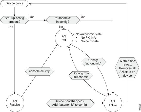
The figure below illustrates the enrollment process described above. In the autonomic networking passive state, the device listens but does not send AD packets. In the autonomic networking active state, the device sends AD packets on all the links. To disable AD packets being sent on a specific link, configure the no autonomic adjacency-discovery command on that link.
Discovering Layer 2 Channels
In certain deployments, devices may be connected across service provider L2VPN infrastructures, where, only a single VLAN is available. For autonomic bootstrap to work, this VLAN must first be discovered. If your setup does not contain such L2VPN components between autonomic devices, skip to Validating the Network.
In the L2VPN cases, channel discovery is used to probe for available VLANs and the device will be able to automatically discover which VLAN should be used when communicating with the other device.
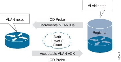
Channel discovery happens automatically on all interfaces when Autonomic Networking is enabled on the device. Autonomic Networking is enabled by default on devices with no configuration, assuming that they have Autonomic Networking functionality, but it will be passive, in other words, they will only be able to receive and answer channel discovery probes. Active sending of channel discovery probes occurs only when the device has a domain certificate. Channel discovery probes are sent with incrementing VLAN IDs, making sure that all neighbors are discovered. Neighbors will be dynamically discovered as a result. The probing continues over time to make sure that newly added neighbors are discovered.
The channel that is created as a result of channel discovery is a combination of a unique virtual L3 interface and a double-tagged ethernet service instance on every interface. The outer VLAN is negotiated with the channel discovery protocol, while the inner tag is fixed to the value 4094. At this time (Cisco IOS release 15.5(3)S) we support discovering one unique neighbor per VLAN ID. If multiple neighbors are attached to a given interface, they need to be reachable across unique VLANs.
Device#show autonomic l2-channels

AN L2 Channel Discovery Info :

Nbr UDI                                       Encap      Our Intf   State      Retry
--------------------------------------------------------------------------------
PID:ISR4451-X/K9 SN:FGL185110BW               0          Gi0/0/0    Active     1
PID:ISR4451-X/K9 SN:FGL185110BX               0          Gi0/0/1    Active     0
Device#show autonomic l2-channels detail

AN L2 Channel Discovery Info :

--------------------------------------------------------------------------------
Nbr UDI                   : PID:ISR4451-X/K9 SN:FGL185110BW
ANI Intf                  : ANI1
Encap                     : 0
Nbr Intf                  : GigabitEthernet0/0/0
Our Intf                  : GigabitEthernet0/0/0
Keepalives Missed         : 1
Channel Status            : Active
--------------------------------------------------------------------------------
Nbr UDI                   : PID:ISR4451-X/K9 SN:FGL185110BX
ANI Intf                  : ANI2
Encap                     : 0
Nbr Intf                  : GigabitEthernet0/0/1
Our Intf                  : GigabitEthernet0/0/1
Keepalives Missed         : 1
Channel Status            : Active
Limiting the VLAN Range Using Intent
Channel discovery on active autonomic networking devices, by default probe all possible VLAN IDs on all interfaces. The possible VLAN ID range used across L2 clouds is significantly smaller than the 4095 possible VLAN IDs. Channel discovery probes are sent every 10 seconds, so probing all VLAN IDs can potentially take a long time. In the current implementation, the VLAN range is 16 - 4090, while probing starts at VLAN 4000. Limiting the VLAN ID range for channel discovery can therefore decrease the bootstrap time for new devices.
Intent is the policy language of an autonomic network. It can be used to restrict the VLAN range.
Configuring the Intent
A registrar must be configured with a domain ID and must be up by running the no shutdown command. The registrar must be live for configuring autonomic intent.
Note | The intent can only be configured on the registrar. |
Validating the Network
The Autonomic Control Plane (ACP) is automatically built-in between autonomic neighbors that belong to the same domain, creating an indestructible virtual out-of-band channel, spanning the entire autonomic network. ACP is created by instantiating a VRF, and automatically assigning a loopback interface to it. The use of a dedicated VRF will make sure that the traffic in the ACP is shielded from any other traffic traversing the device. When a device has authenticated its neighboring device, and validated that it belongs to the same domain, it sets up a secure tunnel to it. The secure tunnels will be added to the mentioned VRF, to create a self-managing overlay network, the ACP.
The ACP is built up hop-by-hop as additional autonomic networking devices are detected and will eventually span the entire network. Since the ACP does not depend on configuration, addressing or routing in the data plane; it essentially provides virtual out-of-band network connectivity to all autonomic networking devices. No configuration is needed to create the ACP, and the state inside the device to create the ACP cannot be altered. The ACP built is totally self-configuring and self-healing, which means if devices are given a different place in the topology, the ACP will heal itself.
The ACP runs an internal routing protocol called RPL (a non-resource intensive routing protocol), which makes it possible to route packets inside the ACP and also to reach external services.
Device#show autonomic neighbors detail


UDI: "PID:ISR4451-X/K9 SN:FGL185110BW"
        Device ID                      64f6.9d35.dab0-3
        Domain ID                      antest
        Address                        FDF6:DBA2:13B6:0:64F6:9D35:DAB0:3
        State                          Nbr inside the Domain
        Credential                     Domain Cert
        Credential Validation          Passed
        Last Validated Time             2016-07-11 12:21:51 IST
        Certificate Expiry Date         2016-07-11 12:32:50 IST
        Certificate Expire Countdown   590 (secs)
        Number of Links connected      1
        Link:
            Local Interface:               ANI1
            Remote Interface:              ANI2
            IP Address:                    FE80::66F6:9DFF:FE35:EE60
            Uptime(Discovered Time):       00:17:11 ( 2016-07-11 12:05:49 IST)
            Last Refreshed time:           0 seconds ago

UDI: "PID:ISR4451-X/K9 SN:FGL185110BX"
        Device ID                      64f6.9d35.dab0-6
        Domain ID                      antest
        Address                        FDF6:DBA2:13B6:0:64F6:9D35:DAB0:6
        State                          Nbr inside the Domain
        Credential                     Domain Cert
        Credential Validation          Passed
        Last Validated Time             2016-07-11 12:21:52 IST
        Certificate Expiry Date         2016-07-11 12:36:01 IST
        Certificate Expire Countdown   781 (secs)
        Number of Links connected      1
        Link:
            Local Interface:               ANI2
            Remote Interface:              ANI1
            IP Address:                    FE80::66F6:9DFF:FE35:DA21
            Uptime(Discovered Time):       00:17:00 ( 2016-07-11 12:06:00 IST)
            Last Refreshed time:           7 seconds ago
The state of the neighbor must show Nbr inside the Domain and credential validation must show passed.
Verification
To see the details of the ACP, use the show autonomic control-plane detail command
Device#show autonomic control-plane detail

VRF Name        cisco_autonomic
Device Address  FDF6:DBA2:13B6:0:64F6:9D35:DAB0:5
RPL             Type = grounded-node, Dag-id = FDF6:DBA2:13B6:0:64F6:9D35:DAB0:1

Neighbor: PID:ISR4451-X/K9 SN:FGL185110BW
        Uptime(Created Time): 00:17:11 ( 2016-07-11 12:05:51 IST)
        Supported ACP Channel: IPv6 GRE Tunnel
        Negotiated ACP Channel: IPv6 GRE Tunnel
                Tunnel Name                    Tunnel100040
                Tunnel Source Interface        ANI1
                Tunnel Source                  FE80::66F6:9DFF:FE35:DB40
                Tunnel Destination             FE80::66F6:9DFF:FE35:EE60
        Supported ACP Security: IPSec, DIKE
        Negotiated ACP Security: DIKE

Neighbor: PID:ISR4451-X/K9 SN:FGL185110BX
        Uptime(Created Time): 00:17:00 ( 2016-07-11 12:06:02 IST)
        Supported ACP Channel: IPv6 GRE Tunnel
        Negotiated ACP Channel: IPv6 GRE Tunnel
                Tunnel Name                    Tunnel100041
                Tunnel Source Interface        ANI2
                Tunnel Source                  FE80::66F6:9DFF:FE35:DB41
                Tunnel Destination             FE80::66F6:9DFF:FE35:DA21
        Supported ACP Security: IPSec, DIKE
        Negotiated ACP Security: DIKE
This output shows the VRF name, and for each autonomic neighbor: A device address, tunnel details, the UDI of the neighbor and negotiated ACP security are displayed. If these details are not present, refer the Troubleshooting section.
Verifying Reachability
Reachability across the ACP can be verified through ping. You should be able to ping any device in the autonomic networking domain. Find the IPv6 address of the enrolled devices using the show autonomic registrar devices accepted detail command. The VRF name to be used for ping can be found from the output of show autonomic control-plane detail command.
To ping a device, use ping vrf vrf-name ipv6-address command
Device#ping vrf cisco_autonomic FD08:2EEF:C2EE:0:6:F6AC:3BE0:2

Type escape sequence to abort.
Sending 5, 100-byte ICMP Echos to FD08:2EEF:C2EE:0:6:F6AC:3BE0:2, timeout is 2 seconds:
!!!!!
Success rate is 100 percent (5/5), round-trip min/avg/max = 1/1/1 ms
Once all devices have joined the ACP, and are reachable as described above, advanced services can be enabled which allow remote access to devices through the ACP, automated configuration download, and syslog in the ACP.
Enabling NOC Services
Generic NOC Setup
By default, the ACP is self-securing, and it is not possible to use it from a non-autonomic device. Practically, it is desirable that the network can communicate with non-autonomic devices, such as servers for AAA, syslog, configuration download and so on.
To establish connectivity between an autonomic network and a non-autonomic network, it is necessary to define a specific interface as belonging to the ACP. Then, all servers connected to that interface can access the ACP. To configure an interface to connect into the ACP, configure the following command on the interface connecting the external devices.
enable
configure terminal
interface GigabitEthernet0/0
autonomic connect
After configuring the autonomic connect command, configure IPv6 address on the interface. This device will act as a gateway between the autonomic network and the non-autonomic network. The external devices connecting to autonomic interface needs to be configured with ipv6 address from the same subnet.
Note | The ACP only supports IPv6. Therefore, non-autonomic devices connecting on an autonomic connect interface must also use IPv6. |
The autonomic connect command is supported only on L3 interface. For devices which only have L2 interface, namely Cisco Aggregate Series Router 901, the autonomic connect command should be configured on the EVC.
Make sure that the interface is in global VRF before configuring the autonomic connect command.
Server Setup
The interface which connects a server to the autonomic connect interface gives full access to the ACP. The autonomic connect subnet has unlimited access to the ACP, and should therefore be highly restricted to only machines that need ACP access. It should also be in a physically secure environment.
Most servers also require access to the NOC, or the data plane of the network. The setup below shows how this can be achieved.
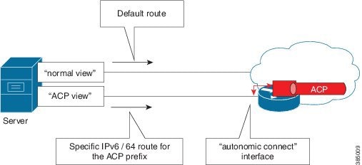
The autonomic connect interface gives access only to the ACP. Therefore, practically, a server should be set up with two interfaces (physical or virtual), one for the ACP, and one for the normal data plane of the network. The default route on the server should point to the non-ACP interface. A static route should be configured for the ACP interface, pointing to the /64 subnet of the ACP. This can be found by looking at the device addresses, using the show autonomic device command. Use the first 64 bits as a static route into the ACP.
Verifying Reachability to Autonomic Networking Devices from External Non-Autonomic Network
Ping any autonomic networking device on its ACP address, from the management or Linus server, and verify the reachability to the autonomic networking devices over ACP.
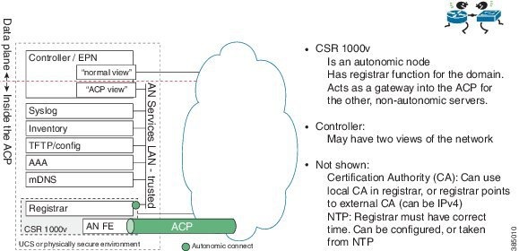
Over time, several servers are likely to require access to the ACP; for example AAA, Syslog, mDNS, and so on. Also, a management station or controller may require access to the ACP, to have a secure connection to all devices, independent of their configuration. The complete NOC setup with all servers could be represented as shown in the figure below. The example shows a set of servers that require access to the ACP, co-located on a UCS blade with a CSR 1000v. The CSR 1000v can act as the registrar for this autonomic network.
%AN-6-CONFIG_DOWNLOAD_STARTED: Config download started on the Device (Addr <Device Address>)
%AN-6-CONFIG_DOWNLOAD_SUCCESS: Config download at the Device (Addr <Device Address>)is Successful
Example:
%AN-6-CONFIG_DOWNLOAD_STARTED: Config download started on the Device (Addr FD57:4317:43D7:0:64F6:9D35:DAB0:2)
Example:
%AN-6-CONFIG_DOWNLOAD_SUCCESS: Config download at the Device (Addr FD57:4317:43D7:0:64F6:9D35:DAB0:2)is Successful
Announcing Services
Autonomic Networks also requires access to IPv6 enabled services like AAA, Syslog, TFTP and others for normal operation. Instead of configuring those services on every device, autonomic networking uses Service Discovery (SD) to discover such services. SD in autonomic networking uses mDNS for service announcements. Each autonomic networking device replicates the incoming SD anouncements of new services on all other ports, eventually flooding the service announcements to all autonomic networking devices in the network.
To announce these services, it is recommended that you use a Linux service called Avahi mDNS to send mDNS announcements for services that should be available inside the autonomic network. The Avahi service can be installed on the same platform where the services are deployed, or on a separate device. However, both the platforms on which Avahi runs, and the services have to be located on the same subnet, as was earlier connected to the autonomic network.
To configure the Avahi mDNS Linux daemon, see http://www.avahi.org/wiki/AboutAvahiand http://manpages.ubuntu.com/manpages/precise/en/man8/avahi-daemon.8.html for more details.
To configure the Avahi configuration to announce an AAA server in the ACP, create a file aaa.service in the "/etc/avahi/services" directory path, with the help of the followings:
<service-group>
  <name replace-wildcards="yes">AAA on %h</name>
  <service>
    <type>_aaa._udp</type>
    <txt-record>acct_port=1813;</txt-record>
    <txt-record>auth_port=1812;</txt-record>
    <txt-record>secret_key=rad123;</txt-record>
  </service>
</service-group>
Note | Only RADIUS is currently (December 2015; 15.6(1)S) supported. Other protocols or parameters are not supported. |
In this example the AAA service resides on the same server as the Avahi daemon is running on (otherwise, there would be a host-name attribute specified in the Avahi configuration file). The service is announced with three text attributes; the accounting port, the authentication port, and the secret used when communicating with the AAA server. These text attributes are parsed by the autonomic networking devices, allowing for zero-touch AAA configuration.
<service-group>
  <name replace-wildcards="yes">Syslog on %h</name>
  <service>
    <type>_syslog._udp</type>
  </service>
</service-group>
The only flag needed is type, which specifies the UDP port used for the services. The attribute _syslog._udp specifies the official DNS-SD name used for syslog.
<service-group>

  <name replace-wildcards="yes">CONFIG on %h</name>

  <service>
    <type>_config._udp</type>
    <txt-record>path=autonomic-networking/;</txt-record>
  </service>

</service-group>
The type flag specifies the official DNS-SD name for TFTP. The extra flag here is the txt-record, which specifies the path where the filenames can be found on the TFTP server. This is a sub-directory of the TFTP-directory configured on the TFTP server.
Verifying Services Learnt
Execute the show autonomic service command on the registrar to verify the service announcements distributed over ACP to all devices.
Device#show autonomic service

Service IP-Addr
Syslog 5000::100
AAA 5000::100
AAA Accounting Port 1813
AAA Authorization Port 1812
Autonomic registrar FD57:4317:43D7:0:4403:A743:28F2:1
ANR type IOS RA
Config Server Address UNKNOWN
Auto IP Server UNKNOWN
If you are not able to see any of the services, refer to the Troubleshooting section.
Note | If a service has been announced correctly, it does not mean that the service is up and running. Ensure that the services are configured correctly and are running on the server. |
Syslog
After learning the syslog service, autonomic networking automatically configures syslog server details on all the nodes. All autonomic networking related syslog with discriminator %AN-* will be sent to the syslog server over the ACP.
Verification
You should now receive autonomic networking syslogs, like the ones shown below:
Syslog on the registrar when enrolling a new device:
%AN-6-DEVICE_ALLOWED_BY_ANR: Device with UDI (UDI) connected to Proxy (Addr Device Address) on the interface Physical interface of proxy is allowed by Autonomic registrar (Addr Device Address of Registrar) in its domain domain-id and has been assigned IP Addr (Device Address assigned to new device) and Device ID (Device-id assigned to new device)
Example:
%AN-6-DEVICE_ALLOWED_BY_ANR: Device with UDI (PID:ISR4451-X/K9 SN:FGL19231046) connected to Proxy (Addr FD57:4317:43D7:0:64F6:9D35:DAB0:1) on the interface GigabitEthernet0/0/0 is allowed by Autonomic registrar (Addr FD57:4317:43D7:0:64F6:9D35:DAB0:1) in its domain an-cisco.com and has been assigned IP Addr (FD57:4317:43D7:0:64F6:9D35:DAB0:2) and Device ID (64f6.9d35.dab0-2)
Syslog on device when a new device in enrolled by registrar:
%AN-5-DEVICE_BOOTSTRAPPED_BY_ANR: Device with UDI (UDI) and (Addr Device Address) has been boot strapped by autonomic registrar, in autonomic domain domain-id
Example
%AN-5-DEVICE_BOOTSTRAPPED_BY_ANR: Device with UDI (PID:ISR4451-X/K9 SN:FGL19231046) and (Addr FD57:4317:43D7:0:64F6:9D35:DAB0:2) has been boot strapped by autonomic registrar, in autonomic domain an-cisco.com
Note | The normal syslog server that you have configured will also receive autonomic networking syslog messages. |
SSH Into a Remote Device
Autonomic networking automatically configures AAA related configurations after learning the service. The management station or any other device can login to the autonomic networking device using SSH. The device will use the autonomic networking SD discovered AAA server to authenticate the request.
Note | Login through Telnet is not supported, only SSH is supported. |
Ensure that AAA server is properly configured and started before trying to remotely login to the device.
Verification
You should now be able to reach any device through the ACP.
[root@management-server  ~]# ssh andt@FD08:2EEF:C2EE:0:6:F6AC:3BE0:1
Password:

Device#
Device#show autonomic device

        Status                         Enabled
        Type                           Autonomic Node
        UDI                            PID:ISR4451-X/K9 SN:FGL185110BY
        Device ID                      64f6.9d35.dab0-5
        Domain ID                      antest
        Domain Certificate             (sub:) ou=antest+serialNumber=PID:ISR4451-X/K9 SN:FGL185110BY,cn=64f6.9d35.dab0-5
        Certificate Serial Number      08
        Device Address                 FDF6:DBA2:13B6:0:64F6:9D35:DAB0:5
        Domain Cert is Valid
Configuration Download
Every greenfield node which has bootstrapped without a start-up configuration, joined the ACP, and discovered a TFTP server through SD, would attempt to pull in a configuration from that server. Devices with a start-up configuration will not show such a behavior.
For this to work, the configuration server must be announced in mMDS, and a configuration file must be in the sub-directory (parameter in the mDNS setup) of the TFTP base directory.
Note | UDIs contain spaces and colons (:), which are not allowed in file names. Therefore, the spaces and colons in the UDI must be replaced in the file name with an underscore (_). |
UDI : PID:ISR4331/K9 SN:FDO1830C01J
Correnspeoding file name: PID_ISR4331_K9_SN_FDO1830C01J.conf
On successful download the following syslog message is generated:
%AN-6-CONFIG_DOWNLOAD_STARTED: Config download started on the Device (Addr Device Address)
%AN-6-CONFIG_DOWNLOAD_SUCCESS: Config download at the Device (Addr Device Address)is Successful
%AN-6-CONFIG_DOWNLOAD_STARTED: Config download started on the Device (Addr FD57:4317:43D7:0:64F6:9D35:DAB0:2)
%AN-6-CONFIG_DOWNLOAD_SUCCESS: Config download at the Device (Addr FD57:4317:43D7:0:64F6:9D35:DAB0:2)is Successful
In this release, (December 2015, release 15.6(1)S) downloaded configuration is not saved automatically by the autonomic network. You must save the configuration explicitly. If the device reloads after configuration download, autonomic network will not initiate the configuration download again.
Note | The automated TFTP download takes place only once, immediately after the device has joined the ACP and received the SD update. If the configuration files are updated later at the TFTP server, the administrator has to remotely log on to the device, and initiate a manual TFTP download. To download the configuration file through ACP, configure the TFTP source interface as the loopback interface created by the autonomic network: ip tftp source-interface loopback interface name. |
Additional Tasks
By-Passing Non Autonomic Devices
Option 1: Tunneling over non-autonomic devices
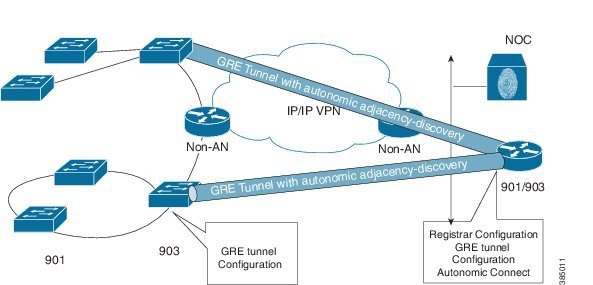
Autonomic networking is topology independent. You must carefully handle the non-autonomic layer 3 clouds, backbones, or devices that are part of the data plane, which currently do not support autonomic networking. A typical deployment involving non-autonomic layer 3 cloud is shown in the figure below.
To cross non-autonomic layer 3 networks, adjacency discovery packets can be sent to remote neighbors by using pre-established tunneling technologies that emulate direct connectivity between devices. For example, Layer 3 Generic Routed Encapsulation (GRE) tunnels, DMVPN, and MPLS Pseudowires. To do this, configure the tunnel and then configure autonomic adjacency-discovery under the tunnel interface.
interface interface-name
autonomic adjacency-discovery
Option 2: Connecting over non-autonomic layer 2 cloud
In some deployments there might be a layer 2 cloud with non-autonomic devices. In such cases, devices in the layer 2 cloud must be configured to pass through autonomic networking packets transparently. This should allow untagged or tagged or double-tagged traffic to pass through.
Backing Up Registrar
To back up the registrar, you can copy the ANR_ACC.an and ANR_QUA.an files from the database location of the registrar to a server. By default the database location is nvram:. In the event of a registrar failure, if the registrar has to be replaced with a new device, copy the backed up files ANR_ACC.an and ANR_QUA.an to the flash: path of the new device, and bring up the registrar after configuring the database URL as flash: path.
Troubleshooting Autonomic Networking
Verify Status of the Registrar
Verify status of the registrar
The show autonomic registrar command shows the status of the registrar. On successful configuration of the registrar, the status needs to be Autonomic Registrar Live.
Device#show autonomic registrar

        Domain ID                   cisco.com
        Whitelist                      flash:whitelist.txt
        Database URL                   nvram:
        Status                      Autonomic Registrar Live
        Address                        FD08:2EEF:C2EE:0:6:F6AC:3BE0:1
        Certificate                    (sub:) cn=ANRA-CS
-
If the status of the registrar is shown as Autonomic Registrar Shut or Autonomic Registrar in Configuration then run the no shut under the registrar configuration mode to make it live.
-
If the status of the registrar shows Autonomic Registrar CA Live Pending, then wait for a couple of minutes for the registrar to go live.
Syslog on registrar:
%AN-4-DEVICE_ALREADY_REGISTERED_BY_ANR: Device with UDI (<UDI>) connected to Proxy (Addr <Device Address>) on interface <Physical interface of proxy> is already registered by autonomic registrar in its domain <domain-id> with a different public key
Example:
%AN-4-DEVICE_ALREADY_REGISTERED_BY_ANR: Device with UDI (PID:ISR4451-X/K9 SN:FGL185110BW) connected to Proxy (Addr FD57:4317:43D7:0:64F6:9D35:DAB0:2) on interface GigabitEthernet0/0/1 is already registered by autonomic registrar in its domain an-cisco.com with a different public key
Verify Whether a Device Received Domain Certificate
Verify enrolled devices details
To verify whether a device has received a domain certificate use the show autonomic device command.
Example:
Device#show autonomic device
        Status                         Enabled
        Type                           Autonomic Node
        UDI                            PID:ISR4451-X/K9 SN:FGL185110BY
        Device ID                      64f6.9d35.dab0-5
        Domain ID                      antest
        Domain Certificate             (sub:) ou=antest+serialNumber=PID:ISR4451-X/K9 SN:FGL185110BY,cn=64f6.9d35.dab0-5
        Certificate Serial Number      08
        Device Address                 FDF6:DBA2:13B6:0:64F6:9D35:DAB0:5
        Domain Cert is Valid
-
Check whether the device and CA certificate are present using the show crypto pki certificates command.
-
If the certificate is present, check whether the system clock is within the certificate validity period.
-
If system clock is not within the certificate validity period, then check if the clock of the device is in sync with the Registrar or CA server.
-
If the clock is in sync, check whether the certificate is revoked from the CA server or verify the renewed settings of the CA server.
Note
Once the certificate expires, the device tries to re-enroll after 15 minutes.
Verify Enrolled Devices Details
Verify enrolled devices details
The enrolled devices can be viewed using the show autonomic registrar devices accepted detail command.
Device#show autonomic registrar devices accepted detail

UDI: "PID:A901-12C-FT-D SN:CAT1702U14Y"
        Device ID:                     0006.f6ac.3be0-1
        Address:                       FD08:2EEF:C2EE:0:6:F6AC:3BE0:1
        Key Len:                       422
        Key data:                     308201A2300D06092A864886F70D01010105000382018F003082018A0282018100C2ECDD51CC34B1DABC8B910AF9433178EB9B406DDE22D03CF2D319D587E88E34F63F4ED6944EFCED1801F24D1DF3D25B8ECAE8D397CE5DCCFAABB9FE647BEE0C6E39007B92662963463EE5628397B19F52B90B2AE0560596047F8B257D32D4352E749E40CD2F0A24188C6D3B74B3CD90709FA92CB04DC78687CCBBCC2B0698108143B04447C5962AECBA5F12632DA9E45EE9B131B9139C0C09F31E34E08AECD624330BC3D82E1BAF3149364C9E829E2A7E0A75FBED5B0BBC65D31291CF2B6CD2E1795F713E5FAFC769BAFC7CD658C202A5E6527BAF2F4C45BA42C585A43E8D5E7646F383713D63A1023E4B1526D97704126E2B6724A70C4166FD6E4567983E56E4F4D1D93B63CF8EBD50D7EFC0A66CF3F1653C4EE706813E9C29A084CA8DC3B5E529859C60ECAC5441694CEF77A63DF1D1F4B452399F6D30E4F6100A47B8615A4D4C2FF210575E7E7889A3941BE5B8143230A4FD9E803A06998AEA0EFEB447A999F7FAD3B9E5D93AD4BDCDCDA50BB1B71AB009FEA6D9115165D2CB3FA0FB496F0203010001
-
If the expected device is not seen in the accepted device output, verify whether the device is quarantined using the show autonomic registrar devices quarantine command.
-
If the device is quarantined, update the whitelist to add the quarantined device. Refer to Updating the Whitelist for steps.
Note
To allow a quarantined device, the device-accept udi command under registrar can be used. But this is not recommended.
Verifying quarantined devices
Verifying quarantined devices
The list of quarantined devices can be seen using the show autonomic registrar devices quarantine command.
Device#show autonomic registrar devices quarantine

Sr no      Unique Device Identifier
--------------------------------------------------------------------------------
1          PID:A901-6CZ-FT-A SN:CAT1719U18F
Verify Channel Discovery
Verify channel discovery
The result of channel discovery can be seen using the show autonomic l2-channels detail command.
Device#show autonomic l2-channels detail

AN L2 Channel Discovery Info :

--------------------------------------------------------------------------------
Nbr UDI                   : PID:ISR4451-X/K9 SN:FGL185110BW
ANI Intf                  : ANI1
Encap                     : 0
Nbr Intf                  : GigabitEthernet0/0/0
Our Intf                  : GigabitEthernet0/0/0
Keepalives Missed         : 1
Channel Status            : Active
--------------------------------------------------------------------------------
Nbr UDI                   : PID:ISR4451-X/K9 SN:FGL185110BX
ANI Intf                  : ANI2
Encap                     : 0
Nbr Intf                  : GigabitEthernet0/0/1
Our Intf                  : GigabitEthernet0/0/1
Keepalives Missed         : 1
Channel Status            : Active
-
Check whether the link or interface is up. If not, bring up the interface.
-
If there is a non-autonomic network layer 2 cloud in between, verify whether the AN traffic can pass transparently through the layer 2 cloud. Ensure that layer 2 cloud allows untagged or tagged or double tagged traffic to pass through.
-
If the channels are still not seen, enable the debug autonomic Neighbor-Discovery all moderate command on both routers and check whether channel discovery probes are sent and received.
Verify Neighbor Discovery
Verify neighbor discovery
To verify whether neighbor discovery is successful, check the output of the show autonomic neighbors detail command.
Device#show autonomic neighbors detail


UDI: "PID:ISR4451-X/K9 SN:FGL185110BW"
        Device ID                      64f6.9d35.dab0-3
        Domain ID                      antest
        Address                        FDF6:DBA2:13B6:0:64F6:9D35:DAB0:3
        State                          Nbr inside the Domain
        Credential                     Domain Cert
        Credential Validation          Passed
        Last Validated Time             2016-07-11 12:21:51 IST
        Certificate Expiry Date         2016-07-11 12:32:50 IST
        Certificate Expire Countdown   590 (secs)
        Number of Links connected      1
        Link:
            Local Interface:               ANI1
            Remote Interface:              ANI2
            IP Address:                    FE80::66F6:9DFF:FE35:EE60
            Uptime(Discovered Time):       00:17:11 ( 2016-07-11 12:05:49 IST)
            Last Refreshed time:           0 seconds ago

UDI: "PID:ISR4451-X/K9 SN:FGL185110BX"
        Device ID                      64f6.9d35.dab0-6
        Domain ID                      antest
        Address                        FDF6:DBA2:13B6:0:64F6:9D35:DAB0:6
        State                          Nbr inside the Domain
        Credential                     Domain Cert
        Credential Validation          Passed
        Last Validated Time             2016-07-11 12:21:52 IST
        Certificate Expiry Date         2016-07-11 12:36:01 IST
        Certificate Expire Countdown   781 (secs)
        Number of Links connected      1
        Link:
            Local Interface:               ANI2
            Remote Interface:              ANI1
            IP Address:                    FE80::66F6:9DFF:FE35:DA21
            Uptime(Discovered Time):       00:17:00 ( 2016-07-11 12:06:00 IST)
            Last Refreshed time:           7 seconds ago
If the output shows the state of the neighbor as Nbr outside the Domain and credential validation is shown as Failed, check whether the clock of the neighbor is synced and check the certificate validity date.
Verify Autonomic Control Plane
Verify autonomic control plane
The show autonomic control-plane detail command shows the details of the autonomic control plane.
Device#show autonomic control-plane detail

VRF Name        cisco_autonomic
Device Address  FDF6:DBA2:13B6:0:64F6:9D35:DAB0:5
RPL             Type = grounded-node, Dag-id = FDF6:DBA2:13B6:0:64F6:9D35:DAB0:1

Neighbor: PID:ISR4451-X/K9 SN:FGL185110BW
        Uptime(Created Time): 00:17:11 ( 2016-07-11 12:05:51 IST)
        Supported ACP Channel: IPv6 GRE Tunnel
        Negotiated ACP Channel: IPv6 GRE Tunnel
                Tunnel Name                    Tunnel100040
                Tunnel Source Interface        ANI1
                Tunnel Source                  FE80::66F6:9DFF:FE35:DB40
                Tunnel Destination             FE80::66F6:9DFF:FE35:EE60
        Supported ACP Security: IPSec, DIKE
        Negotiated ACP Security: DIKE

Neighbor: PID:ISR4451-X/K9 SN:FGL185110BX
        Uptime(Created Time): 00:17:00 ( 2016-07-11 12:06:02 IST)
        Supported ACP Channel: IPv6 GRE Tunnel
        Negotiated ACP Channel: IPv6 GRE Tunnel
                Tunnel Name                    Tunnel100041
                Tunnel Source Interface        ANI2
                Tunnel Source                  FE80::66F6:9DFF:FE35:DB41
                Tunnel Destination             FE80::66F6:9DFF:FE35:DA21
        Supported ACP Security: IPSec, DIKE
        Negotiated ACP Security: DIKE
If ACP is not up, check whether the certificate of the neighbor is valid. Also, check whether the state of the neighbor in the show autonomic neighbors detail command output is Nbr inside the Domain.
Verify Autonomic Service Discovery
Verify autonomic service discovery
The show autonomic service command lists the service discovered by AN.
Router#show autonomic service

Service IP-Addr
Syslog 5000::100
AAA 5000::100
AAA Accounting Port 1813
AAA Authorization Port 1812
Autonomic registrar FD57:4317:43D7:0:4403:A743:28F2:1
ANR type IOS RA
Config Server Address UNKNOWN
Auto IP Server UNKNOWN
-
If the output on the registrar does not show the services published, check whether the show mdns cache command shows the services.
-
If the show mdns cache command does not show the services, check whether Avahi mDNS service is running on Linux server in NOC. If Avahi service is not running start the Avahi service.
-
If Avahi service is running, check whether the services are configured properly. If the services are not configured properly, modify the services and restart the Avahi service.
-
If the device is a non-registrar AN node and the show mdns cache command does not show the published services, follow step 1 to 3 mentioned above.
Verify the configured intent
Verify the configured intent
Executeshow autonomic intent command to verify the configured intent range. Intent is automatically sent to all nodes in an autonomic domain. So every node should show the same intent.
Router#show autonomic intent

Intent File  : Available
Version Num  : 1443520505 (Parsed)
Version Time : 2015-09-29 09:55:05 UTC
Outer Vlans  : 30-35,40,45
Outer Vlans count : 8
If the configured intent is not applied there are probability of exit command not executed after configuring intent. If exit command is not executed intent configurations does not take effect. Reconfigure the intent and execute exit in the intent configuration mode to apply the intent.
Verify the Status of the Autonomic Interfaces
Verify the status of the autonomic interfaces
Run the show autonomic interfaces command to verify the autonomic state of the interfaces.
Router#show autonomic interfaces
Interface                 Channel Disc    AD Enabled      Intf Type
--------------------------------------------------------------------------------
GigabitEthernet0/0/0      Probing         No              L3 untagged If
GigabitEthernet0/0/1      Probing         No              L3 untagged If
GigabitEthernet0/0/2      None            No              L3 untagged If
GigabitEthernet0/0/3      None            No              L3 untagged If
Loopback100000            None            No              Virtual If
ANI1                      None            Yes             Virtual If
ANI2                      None            Yes             Virtual If
Tunnel100040              None            No              Virtual If
Tunnel100041              None            No              Virtual If
Device which is already enrolled (device with valid certificate) will send CD probe through all physical Ethernet interface which are UP (if no autonomic is not configured on interface). All Ethernet interface which are up on an enrolled device will show Channel discovery state as Probing. On interfaces where adjacency (neighbor) discovery is enabled AD Enabled status will be Yes (AN enabled AD on AN created channel interfaces). Interface type will show whether the interface is a tagged or untagged interface.
Clear Commands
The clear autonomic device command resets the device and deletes all Autonomic Networking state.
The clear autonomic neighbor [udi] command clears all the neighbor entries or a specific neighbor, if UDI is specified.
If a device is reset, such that it needs to re-enrol on a Registrar, the state on the Registrar for that device has to be cleared manually with the clear autonomic registrar accepted-device [udi] command.
AN Syslog messages explained
Syslog messages for verifying successful enrollment
Syslog on Registrar when enrolling a new device
%AN-6-DEVICE_ALLOWED_BY_ANR: Device with UDI (UDI) connected to Proxy (Addr Device Address) on the interface Physical interface of proxy is allowed by Autonomic registrar (Addr Device Address of Registrar) in its domain domain-id and has been assigned IP Addr (Device Address assigned to new device) and Device ID (Device-id assigned to new device)
Example:
%AN-6-DEVICE_ALLOWED_BY_ANR: Device with UDI (PID:ISR4451-X/K9 SN:FGL19231046) connected to Proxy (Addr FD57:4317:43D7:0:64F6:9D35:DAB0:1) on the interface GigabitEthernet0/0/0 is allowed by Autonomic registrar (Addr FD57:4317:43D7:0:64F6:9D35:DAB0:1) in its domain an-cisco.com and has been assigned IP Addr (FD57:4317:43D7:0:64F6:9D35:DAB0:2) and Device ID (64f6.9d35.dab0-2)
Syslog on device when a new device in enrolled by Registrar
%AN-5-DEVICE_BOOTSTRAPPED_BY_ANR: Device with UDI (UDI) and (Addr Device Address) has been boot strapped by autonomic registrar, in autonomic domain domain-id
Example:
%AN-5-DEVICE_BOOTSTRAPPED_BY_ANR: Device with UDI (PID:ISR4451-X/K9 SN:FGL19231046) and (Addr FD57:4317:43D7:0:64F6:9D35:DAB0:2) has been boot strapped by autonomic registrar, in autonomic domain an-cisco.com
Syslog messages when a device attempts to enrol again and the state on the registrar is not cleared
From release 15.6(2)S onwards when a device attempts to enrol again and the state on the registrar is not cleared the following syslog will be generated.
%AN-4-DEVICE_ALREADY_REGISTERED_BY_ANR: Device with UDI (UDI) connected to Proxy (Addr device Address) on interface interface is already registered by autonomic registrar in its domain domain-id with a different public key
Example:
%AN-4-DEVICE_ALREADY_REGISTERED_BY_ANR: Device with UDI (PID:ISR4331/K9 SN:FDO1830C01J) connected to Proxy (Addr FD57:4317:43D7:0:4403:A743:28F2:2) on interface GigabitEthernet0/1/1 is already registered by autonomic registrar in its domain an-cisco.com with a different public key
Syslog messages when connectivity to neighbor is lost
%AN-5-NBR_LOST: Device with ACP (Addr <Device Address>) lost connectivity to its Neighbor (Addr <Neighbor's Device Address>) on interface <Physical Interface>
Example:
%AN-5-NBR_LOST: Device with ACP (Addr FD57:4317:43D7:0:64F6:9D35:DAB0:2) lost connectivity to its Neighbor (Addr FD57:4317:43D7:0:64F6:9D35:DAB0:4) on interface GigabitEthernet0/0/1
Syslog messages when ACP channel goes down
%AN-6-ACP_CHANNEL_TO_NBR_REMOVED: Removed ACP Tunnel100312 from Device (Addr <Device Address>) to Neighbor (Addr <Neighbor's Device Address>) connected on interface <Physical Interface>
Example:
%AN-6-ACP_CHANNEL_TO_NBR_REMOVED: Removed ACP Tunnel100312 from Device (Addr FD57:4317:43D7:0:64F6:9D35:DAB0:2) to Neighbor (Addr FD57:4317:43D7:0:64F6:9D35:DAB0:4) connected on interface GigabitEthernet0/0/1
Resetting Autonomic Functions and Devices
Resetting autonomic functions on a generic device
The clear autonomic device command resets the device and deletes all autonomic networking state. It also removes the certificate information. The device attempts to re-enroll right away if there is an autonomic domain neighbour. The registrar does not automatically accept the device, for security reasons. The state of the device should be cleared on the registrar using the clear autonomic registrar accepted-deviceUDI command.
Completely removing a registrar
The no autonomic registrar command will remove all configuration related to a registrar, and all the AN created files in the file system that were configured using the database-url command. By default, the filesystem is nvram. When unconfiguring a registrar with local CA, the crypto server has to be unconfigured manually. In case of an external CA, since the crypto server configuration is done manually, it has to be unconfigured manually.
Note | This is a dangerous operation, because all devices enrolled with this registrar would have to be re-enrolled. This can only be done by going to each device individually and issuing the clear autonomic device command. You may prefer to back up the registrar state, for example, information about the devices enrolled on this registrar. You can back up the registrar by copying the files ANR_ACC.an and ANR_QUA.an from the database location of the registrar to a server. By default the database location is nvram:. |
Debug Commands
debug autonomic bootstrap [All | Events | Packets] [Info | Moderate | Severe]
debug autonomic Infra Events [Info | Moderate | Severe]
debug autonomic Intent [All | Events | Packets] [Info | Moderate | Severe]
debug autonomic Neighbor-Discovery [All | Database | Events | Packets] [Info | Moderate | Severe]
debug autonomic Registrar [All | Database | Events] [Info | Moderate | Severe]
debug autonomic service [AAA | All | ConfigDownload | Events  | IDP | NTP | Packets | SYSLOG | topology] [Info | Moderate | Severe]
Additional References for Autonomic networking
Technical Assistance
| Description | Link |
|---|---|
|
The Cisco Support and Documentation website provides online resources to download documentation, software, and tools. Use these resources to install and configure the software and to troubleshoot and resolve technical issues with Cisco products and technologies. Access to most tools on the Cisco Support and Documentation website requires a Cisco.com user ID and password. |
Feature Information for Autonomic Networking
The following table provides release information about the feature or features described in this module. This table lists only the software release that introduced support for a given feature in a given software release train. Unless noted otherwise, subsequent releases of that software release train also support that feature.
Use Cisco Feature Navigator to find information about platform support and Cisco software image support. To access Cisco Feature Navigator, go to www.cisco.com/go/cfn. An account on Cisco.com is not required.Copyright © 2017, Cisco Systems, Inc. All rights reserved.