The IPsec VPN policy is used to establish the VPN connection between two peers. ISA550 and ISA550W support up to 50 IPsec VPN tunnels. ISA570 and ISA570W support up to 100 IPsec VPN tunnels.
Note Before you create an IPsec VPN policy, make sure that the IKE and transform policies are configured. Then you can apply the IKE and transform policies to the IPsec VPN policy.
1. Click VPN > Site-to-Site > IPsec Policies.
2. To add a new IPsec VPN policy, click Add.
Other options: To edit an entry, click the Edit (pencil) icon. To delete an entry, click the Delete (x) icon. To delete multiple entries, check them and click Delete.
The IPsec Policies - Add/Edit window opens.
3. In the Basic Settings tab, enter the following information:
• Description: Enter the name for the IPsec VPN policy.
• IPsec Policy Enable: Click On to enable the IPsec VPN policy, or click Off to create only the IPsec VPN policy.
• Remote Type: Specify the remote peer:
– Static IP: Choose this option if the remote peer uses a static IP address. Enter the IP address of the remote peer in the Remote Address field.
– Dynamic IP: Choose this option if the remote peer uses a dynamic IP address.
– FQDN (Fully Qualified Domain Name): Choose this option to use the domain name of the remote network, such as vpn.company.com. Enter the domain name of the remote peer in the Remote Address field.
For the example as illustrated in Figure 3 , the remote site, Site B, has a public IP address of 209.165.200.236. You should choose Static IP and enter 209.165.200.236 in the Remote Address field.
• Authentication Method: Choose one of the following authentication methods:
– Pre-shared Key: Uses a simple, password-based key to authenticate. If you choose this option, enter the desired value that the peer device must provide to establish a connection in the Key field. The pre-shared key must be entered exactly the same here and on the remote peer.
– Certificate: Uses the digital certificate from a third party Certificate Authority (CA) to authenticate. If you choose this option, select a CA certificate as the local certificate from the Local Certificate drop-down list and select a CA certificate as the remote certificate from the Remote Certificate drop-down list. The selected remote certificate on the local gateway must be set as the local certificate on the remote peer.
NOTE: You must have valid CA certificates imported on your security appliance before choosing this option. Go to the Device Management > Certificate Management page to import the CA certificates. See Managing Certificates for Authentication, page 350.
• WAN Interface: Choose the WAN port that traffic passes through over the IPsec VPN tunnel.
• Local Network: Choose the IP address for the local network. If you want to configure the zone access control settings for site-to-site VPN, choose Any for the local network. Then you can control incoming traffic from remote VPN network to the zones over the VPN tunnels.
• Remote Network: Choose the IP address of the remote network. You must know the IP address of the remote network before connecting the VPN tunnel.
For the example as illustrated in Figure 3 , Site A has a LAN IP address of 10.10.10.0 and Site B has a LAN IP address of 10.20.20.0. When you configure site-to-site VPN on Site A, the local network is 10.10.10.0 and the remote network is 10.20.20.0.
If the address object that you want is not in the list, choose Create a new address to add a new address object or choose Create a new address group to add a new address group object. To maintain the address and address group objects, go to the Networking > Address Management page. See Address Management, page 155.
NOTE: The security appliance can support multiple subnets for establishing the VPN tunnels. You should select an address group object including multiple subnets for local and/or remote networks.
4. In the Advanced Settings tab, enter the following information:
• PFS Enable: Click On to enable Perfect Forward Secrecy (PFS) to improve security, or click Off to disable it. If you enable PFS, a Diffie-Hellman exchange is performed for every phase-2 negotiation. PFS is desired on the keying channel of the VPN connection.
• DPD Enable: Click On to enable Dead Peer Detection (DPD), or click Off to disable it. DPD is a method of detecting a dead Internet Key Exchange (IKE) peer. This method uses IPsec traffic patterns to minimize the number of messages required to confirm the availability of a peer. DPD is used to reclaim the lost resources in case a peer is found dead and it is also used to perform IKE peer failover. If you enable DPD, enter the following information:
– Delay Time: Enter the value of delay time in seconds between consecutive DPD R-U-THERE messages. DPD R-U-THERE messages are sent only when IPsec traffic is idle. The default value is 10 seconds.
– Detection Timeout: Enter the value of detection timeout in seconds. If no response and no traffic over the timeout, declare the peer dead. The default value is 30 seconds.
– DPD Action: Choose one of the following actions over the detection timeout:
Hold: Traffic from your local network to the remote network can trigger the security appliance to re-initiate the VPN connection over the detection timeout. We recommend that you use Hold when the remote peer uses a static IP address.
Clean: Terminate the VPN connection over the detection timeout. You must manually re-initiate the VPN connection. We recommend that you use Clean when the remote peer uses dynamic IP address.
Restart: Re-initiate the VPN connection for three times over the detection timeout.
• Windows Networking (NetBIOS) Broadcast: Click On to allow access remote network resources by using its NetBIOS name, for example, browsing Windows Neighborhood. NetBIOS broadcasting can resolve a NetBIOS name to a network address. This option allows NetBIOS broadcasts to travel over the VPN tunnel.
• Access Control: When the local network is set as Any, you can control incoming traffic from the remote VPN network to the zones. Click Permit to permit access, or click Deny to deny access. By default, incoming traffic from the remote network to all zones is permitted.
NOTE: The VPN firewall rules that are automatically generated by the zone access control settings will be added to the list of firewall rules with the priority higher than default firewall rules, but lower than custom firewall rules.
• Apply NAT Policies: Click On to apply the NAT settings for both the local network and the remote network communicating over the VPN tunnel. This option is particularly useful in cases where both sides of a tunnel use either the same or overlapping subnets.
– Translates Local Network: To translate the local network, select a translated address object for the local network.
– Translates Remote Network: To translate the remote network, select a translated address object for the remote network.
If the address object that you want is not in the list, choose Create a new address to add a new address object or choose Create a new address group to add a new address group object. To maintain the address or address group objects, go to the Networking > Address Management page. See Address Management, page 155.
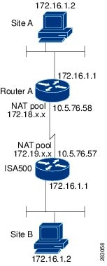
Figure 4 shows a networking example that simulates two merging companies with the same IP addressing scheme. Two routers are connected with a VPN tunnel, and the networks behind each router are the same. For one site to access the hosts at the other site, Network Address Translation (NAT) is used on the routers to change both the source and destination addresses to different subnets.
Figure 8-2 Networking Example that Simulates Two Merging Companies with the Same IP Addressing Scheme
In this example, when the host 172.16.1.2 at Site A accesses the same IP-addressed host at Site B, it connects to a 172.19.1.2 address rather than to the actual 172.16.1.2 address. When the host at Site B to access Site A, it connects to a 172.18.1.2 address. NAT on Router A translates any 172.16.x.x address to look like the matching 172.18.x.x host entry. NAT on the ISA500 changes 172.16.x.x to look like 172.19.x.x.
NOTE: This configuration only allows the two networks to communicate. It does not allow for Internet connectivity. You need additional paths to the Internet for connectivity to locations other than the two sites; in other words, you need to add another router or firewall on each side, with multiple routes configured on the hosts.
• IKE Policy: Choose the IKE policy used for the IPsec VPN policy. You can click IKE Policy Link to maintain the IKE policies, but save your settings on this page first.
• Transform: Choose the transform set used for the IPsec VPN policy. You can click Transform Link to maintain the transform policies, but save your settings on this page first.
• SA-Lifetime: Enter the lifetime of the IPsec Security Association (SA). The IPsec SA lifetime represents the interval after which the IPsec SA becomes invalid. The IPsec SA is renegotiated after this interval. The default value is 1 hour.
5. In the VPN Failover tab, enter the following information:
• WAN Failover Enable: Click On to enable WAN Failover for site-to-site VPN, or click Off to disable it. If you enable WAN Failover, the backup WAN port ensures that VPN traffic rolls over to the backup link whenever the primary link fails. The security appliance will automatically update the local WAN gateway for the VPN tunnel based on the configurations of the backup WAN link. For this purpose, Dynamic DNS has to be configured because the IP address will change due to failover, or let the remote gateway use dynamic IP address.
NOTE: To enable WAN Failover for site-to-site VPN, make sure that the secondary WAN port was configured and the WAN redundancy was set as the Failover or Load Balancing mode.
• Redundant Gateway: Click On to enable Redundant Gateway, or click Off to disable it. If you enable Redundant Gateway, when the connection of the remote gateway fails, the backup connection automatically becomes active. A backup policy comes into effect only if the primary policy fails.
– Select Backup Policy: Choose a policy to act as a backup of this policy.
– Fallback Time to switch from back-up to primary: Enter the number of seconds that must pass to confirm that the primary tunnel has recovered from a failure. If the primary tunnel is up for the specified time, the security appliance will switch to the primary tunnel by disabling the backup tunnel. Enter a value in the range 3 to 59 seconds. The default value is 5 seconds.
NOTE: DPD should be enabled if you want to use the Redundant Gateway feature for IPsec VPN connection.
6. Click OK to save your settings.
7. When both the Site-to-Site VPN feature and the IPsec VPN policy are enabled, a warning message appears saying “Do you want to make this connection active when the settings are saved?”
• If you want to immediately activate the connection after the settings are saved, click the Activate Connection button. After you save your settings, the security appliance will immediately try to initiate the VPN connection. You can check the Status column to view its connection status.
• If you only want to create the IPsec VPN policy and do not want to immediately activate the connection after the settings are saved, click the Do Not Activate button. The connection will be triggered by any traffic that matches the IPsec VPN policy and the VPN tunnel will be set up automatically. You can also click the Connect icon to manually establish the VPN connection.