- Preface
- Product Overview
- Supported Features
- CT5760 Centralized Configuration Example
- Mobility Architecture
- Bring Your Own Device Security Configuration
- Secure WLAN Configuration
- 802.11ac Support on WLC5760 and Catalyst 3850
- Radio Resource Management Configuration
- CleanAir
- Configuring ClientLink (Beamforming)
- High Availability
- Interface Group
- Multicast Configuration
- Installing and Upgrading Software Image on a CT5760
- Adding WLC to Prime
- Application Visibility and Flexible Netflow
- Service Discovery Gateway (mDNS Gateway)
- QoS Configuration
CT5760 Controller Deployment Guide
Bias-Free Language
The documentation set for this product strives to use bias-free language. For the purposes of this documentation set, bias-free is defined as language that does not imply discrimination based on age, disability, gender, racial identity, ethnic identity, sexual orientation, socioeconomic status, and intersectionality. Exceptions may be present in the documentation due to language that is hardcoded in the user interfaces of the product software, language used based on RFP documentation, or language that is used by a referenced third-party product. Learn more about how Cisco is using Inclusive Language.
- Updated:
- July 1, 2014
Chapter: CT5760 Centralized Configuration Example
- Network Topology
- Accessing t he CT5760 Controller Web GUI
- GUI Access for CT5760/3850 Example
- Basic Configuration
- Add Management and Client Interface
- AP Join
- DHCP Snooping and Trust Configuration on CT5760
- WLAN Configuration
- AP and Client Verification
- Security Configuration
- Optional Radius Server Configuration
- Wireless WebAuth and Guest Anchor Solutions
- Configure Parameter-Map Section in Global Configuration
- Configure Customized WebAuth Tar Packages
- Configure Parameter Map with Custom Pages
- Configure Parameter Map with Type Consent and Email Options
- Configure Local WebAuth Authentication
- Configure External Radius for WebAuth
- Configure WLAN with WebAuth
- Configure HTTP Server in Global Configuration
- SNMP Configuration
- IPv6 Configuration
- Enable IPv6 Snooping - CT5760
- Enable IPv6 on Interface - CT5760
CT5760 Centralized Configuration Example
Network Topology
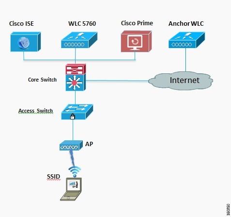
The diagram in Figure 3-1 shows the network topology with only the Unified Access CT5760 controller in a centralized deployment.
Figure 3-1 Network Topology Centralized Configuration
VLANs and IP Addresses
|
|
|
|
CT5760 Controller Configuration Example using CLI
Before you start the controller configuration, ensure that there is complete connectivity between all of the switches in the configuration above.
Console Connection
Before you can configure the switch or controller for basic operations, you must connect it to a PC that uses a VT-100 terminal emulator (such as HyperTerminal, ProComm, or Putty).
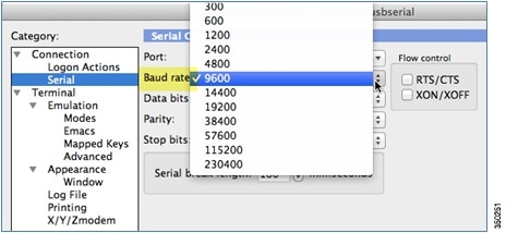
The controller has both EIA/TIA-232 asynchronous (RJ-45) and USB 5-pin mini Type B, 2.0 compliant serial console ports. The default parameters for the console ports are 9600 baud, eight data bits, one stop bit, and no parity. The console ports do not support hardware flow control. Choose the serial baud rate of 9600; if you have issues, try a baud rate of 115200.Figure 3-2 shows an example of a Mac Secure CRT; use similar for PC/Windows Putty, and so on.
Figure 3-2 Mac Secure CRT Example
Startup Wizard
Before you launch the startup wizard, have your IP addresses and VLANs information available. Start without the wizard/initial configuration dialog (check the initial configuration).
% Please answer 'yes' or 'no'.
Would you like to enter the initial configuration dialog? [yes/no]: no
Would you like to terminate autoinstall? [yes]:
Start with the wizard/initial configuration dialog (check the initial config).
----------------------------------
In order to access the device manager, an enable secret is required
If you enter the initial configuration dialog, you will be prompted for the enable
If you choose not to enter the initial configuration dialog, or if you exit setup
without setting the enable secret,
please set an enable secret using the following CLI in configuration mode-
enable secret 0 <cleartext password>
----------------------------------
Would you like to enter the initial configuration dialog? [yes/no]: yes
At any point you may enter a question mark '?' for help. Use ctrl-c to abort configuration dialog at any prompt. Default settings are in square brackets '[]'.
Basic management setup configures only enough connectivity for management of the system, extended setup will ask you to configure each interface on the system
Would you like to enter basic management setup? [yes/no]: yes
Configuring global parameters:
Enter host name [Controller]: CT5760-Controller
The enable secret is a password used to protect access to privileged EXEC and configuration modes. This password, after entered, becomes encrypted in the configuration.
The enable password is used when you do not specify an enable secret password, with some older software versions, and some boot images.
Enter enable password: Admin123
The virtual terminal password is used to protect access to the router over a network interface. Enter virtual terminal password: Cisco123
Configure a NTP server now? [yes]: yes
Enter ntp server address : 10.10.200.1
Enter a polling interval between 16 and 131072 secs which is power of 2:16
Do you want to configure wireless network? [no]: yes
Enter mobility group name: New-Mobility
Setup account for accessing HTTP server? [yes]: yes
Configure SNMP Network Management? [no]: no
Any interface listed with OK? value "NO" does not have a valid configuration
Enter interface name used to connect to the management network from the above interface summary: GigabitEthernet0/0[service port)
Configuring interface GigabitEthernet0/0: Configure IP on this interface? [no]: yes
IP address for this interface: 192.168.2.50
Subnet mask for this interface [255.255.0.0] : 255.255.255.0
Wireless management interface needs to be configured at startup
It needs to be mapped to an SVI that is not Vlan 1 (default)
Enter VLAN No for wireless management interface: 200
Enter IP address mask:: 255.255.255.0
[0] Go to the IOS command prompt without saving this config.
[1] Return back to the setup without saving this config.
Version
The CT5760 controller currently ships with release 3.2.01 or release 3.3.0. You can check this using the command:
Switch Ports Model SW Version SW Image Mode
------ ----- ----- ---------- ---------- ----
* 1 6 AIR-CT5760 03.03.01SE ct5760-ipservicesk9 INSTALL
It is recommended to upgrade to software release 3.3.3 and later. Latest software codes are available on Cisco.com. It is best practice to go through the release notes before upgrading to that software code. Please follow the steps in the Cisco IOS-XE software upgrade document.
To display the WCM and IOSd versions, use the following command:
Accessing the CT5760 Controller Web GUI
You can access the GUI by configuring the out of band management port (GigE 0/0) or by using existing reachable configured interfaces through the network. i.e. create a VLAN and L3 interface to reach the controller.
For best GUI experience, it is best practice to follow the below listed steps:
1.![]() Use the following list of supported browsers:
Use the following list of supported browsers:
2.![]() Upgrade the controller to the latest software version that has additional features and GUI support.
Upgrade the controller to the latest software version that has additional features and GUI support.
3.![]() You must create a username and password to access the GUI. You can configure a local username by issuing the CLI below or you can configure it to use credentials using an authentication server. Make sure the user has privilege 15 as an access level.
You must create a username and password to access the GUI. You can configure a local username by issuing the CLI below or you can configure it to use credentials using an authentication server. Make sure the user has privilege 15 as an access level.
4.![]() By default, https is enabled. You can access the web GUI through https, but if you want to enable http access, you can do so by issuing the CLI below:
By default, https is enabled. You can access the web GUI through https, but if you want to enable http access, you can do so by issuing the CLI below:
WLC5760(config)#username username privilege 15 password password
WLC5760(config)#ip http secure-server
WLC5760(config)#ip http authentication local

Note![]() The ip http authentication local CLI command is not configured by default in older releases. However, it is configured by default in recent releases. Ensure that it is configured once you upgrade to the latest release.
The ip http authentication local CLI command is not configured by default in older releases. However, it is configured by default in recent releases. Ensure that it is configured once you upgrade to the latest release.
Now, you will be able to access the Web GUI interface. Open a browser and type your controller/switch IP address. Example, https://10.10.10.5/. Please refer to the GUI access example below.
GUI Access for CT5760/3850 Example
Step 1![]() GUI access–Open a browser and type your controller IP address. By default https is enabled.
GUI access–Open a browser and type your controller IP address. By default https is enabled.
Note![]() You can setup username/password using the following CLI command:
You can setup username/password using the following CLI command: Controller(config)#username admin privilege 15 password Cisco123. This is an example and not the default username and password.
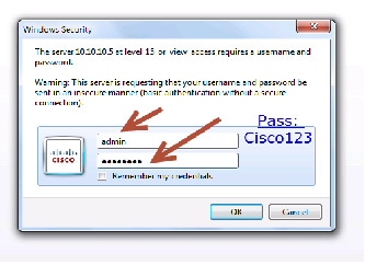
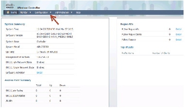
Once you login, you will be directed to the following page:
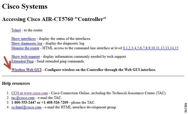
Step 2![]() Click Wireless WEB GUI, this will take you to the home page shown below:
Click Wireless WEB GUI, this will take you to the home page shown below:
Note![]() For additional GUI configuration examples, please see Cisco Unified Access CT5760 Controllers, Catalyst 3850 Switches IOS XE Software release 3.2.2 Web GUI Deployment Guide
For additional GUI configuration examples, please see Cisco Unified Access CT5760 Controllers, Catalyst 3850 Switches IOS XE Software release 3.2.2 Web GUI Deployment Guide
Basic Configuration
For the purpose of this document, CLI commands are used to perform configurations. However, most of the configurations mentioned in this document can also be performed using the GUI.
This section shows the configuration options from the console of the CT5760 for the following:
Add Management and Client Interface
AP Join
Before connecting your Access Points to the network, ensure licenses and the correct time is set on the controller.
Licenses
Licenses are based on the Right-To-Use license model (per AP license price for the CT5760 controller).
You must add the AP licenses you purchased and accept the EULA before connecting your APs. This is how you can do it:
WLC5760#license right-to-use activate apcount 510 slot 1 acceptEULA
Once you apply it, you can check the AP license information using the CLI:
WLC5760#show license right-to-use
Slot# License name Type Count Period left
----------------------------------------------------------
You can also add evaluation licenses for testing purposes:
WLC5760#license right-to-use activate apcount evaluation acceptEULA
For additional license information, please refer to the Cisco Right to Use Licensing FAQ.
Enable Network Time Protocol (NTP) and Setup Time
NTP is very important for several features. It is mandatory to use NTP synchronization on controllers if you use any of these features—Location, SNMPv3, access point authentication, or MFP. The WLC supports synchronization with NTP using authentication.
You can setup NTP during the Initial Wizard configuration. To enable the NTP server use the following command:
WLC5760(config)#ntp server <ip_address>
It is important to setup the correct time on the controller so that the AP can join the controller.
WLC5760#clock set hh:mm:ss day month year
Ensure that you have the correct Country Code set on your controller. To see the current Country Code configured on your controller, please issue the following CLI:
WLC5760(config)#show wireless country configured
Configured Country.............................: US - United States
US - United States : 802.11a Indoor,Outdoor/ 802.11b / 802.11g
To change the country code on your controller, please follow the steps below:
WLC5760(config)#ap dot11 24ghz shutdown
WLC5760(config)#ap dot11 5ghz shutdown
WORD Enter the country code (e.g. US,MX,IN) upto a maximum of 20 countries
Wireless Management Interface
Configuring the Wireless management interface enables the APs to join the controller. Wireless management interface can be configured as part of the Startup Wizard or can be configured by issuing the following command:
WLC5760(config)#wireless management interface vlan 200
Note![]() You need not configure AP Manager or dynamic interfaces on the 5760 controller.
You need not configure AP Manager or dynamic interfaces on the 5760 controller.
Default Gateway
The 5760 controller does not support routing. You must define a default gateway on the controller pointing to the default gateway responsible for routing in the network.
Multicast Forwarding Mode
You must enable the capwap multicast forwarding mode as multicast, even if the multicast forwarding is not enabled. This mode is called Multicast Multicast (MCMC). To use this mode, you must configure a multicast group on your controller. Each AP connected to the controller subscribes to this multicast group, and can receive the multicast flow. You can enable MCMC and configure the multicast group with this command:
WLC5760(config)#ap capwap multicast 239.3.3.3
- The multicast address is used by the controller in order to forward traffic to access points. It is important that it does not match another address in use on your network by other protocols. For example, if you use 224.0.0.251, it breaks mDNS used by some third party applications. It is recommended that the address be in the private range (239.0.0.0 - 239.255.255.255, which does not include 239.0.0.x and 239.128.0.x.). It is also important that the multicast IP address be set to a different value on each WLC. You do not want a WLC that speaks to its access points to reach the APs of another WLC.
- If the access points are on a different subnet than the one used on the management interface, your network infrastructure must provide multicast routing between the management interface subnet and the AP subnet.
Note![]() Do not enable wireless multicast unless it is needed. You might need to enable multicast forwarding in certain networks with heavy multicast application such as Video Streaming, or Bonjour without mDNS proxy, and with large IPV6 client counts.
Do not enable wireless multicast unless it is needed. You might need to enable multicast forwarding in certain networks with heavy multicast application such as Video Streaming, or Bonjour without mDNS proxy, and with large IPV6 client counts.
To configure multicast forwarding on the WLC, use the following command:
WLC5760(config)#wireless multicast
For additional multicast information, refer to the Multicast Configuration chapter in this document.
DHCP Snooping and Trust Configuration on CT5760
It is recommended to use external DHCP server instead of internal DHCP server. DHCP snooping configuration is required on the controller for proper client join functionality. DHCP snooping must be enabled on each client VLAN including the override VLAN, if override is applied on the WLAN. The following example shows how to configure DHCP snooping.
Global DHCP Snooping Configuration:
ip dhcp snooping vlan 100, 200
Enable the bootp-broadcast command. This command is used by clients who send DHCP messages with broadcast addresses and the broadcast bit is set in the DHCP message.
ip dhcp snooping wireless bootp-broadcast enable
Note![]() If upstream is via a port channel, the trust configuration must be configured on the port channel interface as well.
If upstream is via a port channel, the trust configuration must be configured on the port channel interface as well.
interface TenGigabitEthernet1/0/1
description Connection to Core Switch
switchport trunk allowed vlan 100, 200
ip dhcp relay information trusted
Note![]() DHCP snooping must be configured on the Guest Anchor controller for guest access similar to the configuration above.
DHCP snooping must be configured on the Guest Anchor controller for guest access similar to the configuration above.
If you are using an ip-helper address on the interface, you must modify option 82 behavior:
On the DHCP Relay Device (per interface)
On the DHCP Relay Device (global configuration)
WLAN Configuration
When configuring your WLANs, it is best practice to enable Band Select, Fast SSID change, and lower the number of SSID configured on your controller.
Enable Band Selection
Band selection enables client radios that are capable of dual-band (2.4 and 5 GHz) operation to move to a less congested 5 GHz access point. The 2.4 GHz band is often congested. Clients on this band typically experience interference from Bluetooth devices, microwave ovens, and cordless phones as well as co-channel interference from other access points because of the 802.11b/g limit of three non-overlapping channels. To prevent these sources of interference and improve overall network performance, you can configure band selection on the controller.
- Band selection is enabled or disabled globally by default.
- Band selection works by regulating probe responses to clients. It makes 5 GHz channels more attractive to clients by delaying probe responses to clients on 2.4 GHz channels.
- Do not use band selection for voice, as it can slow down roaming.
- Some client types do not work well with band selection enabled.
- Most new clients prefer 5 GHz by default.
- Do not use band selection on high-density designs.
Enable Fast SSID Changing
When fast SSID changing is enabled, the controller allows clients to move faster between SSIDs. When fast SSID is enabled, the client entry is not cleared and the delay is not enforced. This configuration is very important to have for supporting Apple IOS devices.
The fast SSID change is enabled globally on the controller. To enable fast SSID change:
WLAN Configuration Example
Configure a WLAN and assign a client VLAN. Use WPA/PSK for security, and the passkey is cisco123.
wlan corporate 1 corporate band-select
security wpa akm psk set-key ascii 0 cisco123
Voice WLAN
If you are deploying a voice WLAN, apply the best practices below for Voice WLAN configurations:
Enable Voice acm and sip CAC on both the 2.4 GHz and 5 GHz bands under global Config:
WLC5760(config)#ap dot11 24ghz shutdown
WLC5760(config)#ap dot11 24ghz cac voice acm
WLC5760(config)#ap dot11 24ghz cac voice sip
WLC5760(config)#no ap dot11 24ghz shutdown
WLC5760(config)#ap dot11 5ghz shutdown
WLC5760(config)#ap dot11 5ghz cac voice acm
WLC5760(config)#ap dot11 5ghz cac voice sip
WLC5760(config)#no ap dot11 5ghz shutdown
WLC5760(config-wlan)##service-policy output platinum
WLC5760(config-wlan)##service-policy input platinum-up
Enable SIP Snooping under the WLAN if SIP calling is required:
WLC5760(config-wlan)#call-snoop
Note![]() Refer to CAC configuration document if CAC is required in your network.
Refer to CAC configuration document if CAC is required in your network.
AP and Client Verification
Connect an AP to any port configured with Vlan 200 on the L2 switch. Wait until it joins and enter command:
Global AP User Name: Not configured
Global AP Dot1x User Name: Not configured
AP Name / AP Model / Ethernet MAC / Radio MAC / State
---------------------------------------------------------------------------------
AP44d3.ca42.321a / 3602I / 44d3.ca42.321a / 64d9.8942.4090 / Registered
Connect a wireless client to the corporate SSID with the WPA key 'cisco123'. On the controller, you might see the following successful authorization for new client association.
Show wireless client summary from controller to confirm wireless clients.
Security Configuration
This section shows the configuration options from the console of the CT5760:
- Enable Authentication, Authorization, and Accounting (AAA)
- Configure ISE as RADIUS server (10.10.200.60)
- Shared secret - secret
From the CT5760 console (telnet/serial) - Configure AAA
aaa authentication login no_auth none
aaa authentication dot1x default group radius
aaa authentication dot1x Cisco_dot1x group Cisco
aaa authorization network default group Cisco
aaa accounting network default start-stop group Cisco
Optional Radius Server Configuration
aaa server radius dynamic-author
radius-server attribute 6 on-for-login-auth
radius-server dead-criteria time 10 tries 3
radius-server vsa send accounting
radius-server vsa send authentication
This command creates the WLAN with 802.1x security.
wlan corporate1x 2 corporate1x
security dot1x authentication-list Cisco_dot1x
Connect wireless client to corporate-1x with the credentials configured on the AAA server:
Wireless WebAuth and Guest Anchor Solutions
The following sections show a WebAuthentication (WebAuth) configuration and Guest Anchor examples on the CT5760.
Note![]() For a complete webauth configuration, please download the webauth bundle from the following URL: http://software.cisco.com/download/release.html?mdfid=284397235&softwareid=282791507&
For a complete webauth configuration, please download the webauth bundle from the following URL: http://software.cisco.com/download/release.html?mdfid=284397235&softwareid=282791507&
release=3.2.2&relind=AVAILABLE&rellifecycle=&reltype=latest.The readme file has all the GUI and CLI configuration for webauth.
Best practices for Central (CWA) and Local (LWA) WebAuth configurations:
- Release 3.3.3SE and later are the recommended releases for any web-auth network deployments.
- Configure the virtual-ip under the global parameter-map to drop the unauthenticated HTTPS traffic for the LWA scenario.
- Configure per user max HTTP connections (15) and web-auth state time out (5 min) for LWA scenario.
This is how to apply the configuration:
parameter-map type webauth global
Configure Parameter-Map Section in Global Configuration
The parameter map connection configuration mode commands allow you to define a connection- type parameter map. After you create the connection parameter map, you can configure TCP, IP, and other settings for the map.
! First section is to define our global values and the internal Virtual Address.
! This should be common across all WCM nodes.
parameter-map type webauth global
PARAMETER-MAP TYPE WEBAUTH WEBPARALOCAL?
REDIRECT ON-SUCCESS HTTP://9.12.128.50/WEBAUTH/LOGINSUCCESS.HTML
Configure Customized WebAuth Tar Packages
copy tftp://10.1.10.100/WebAuth/webauth/ webauth_consent.html flash:webauth_consent.html
copy tftp://10.1.10.100/WebAuth/ webauth_success.html flash: webauth_success.html
copy tftp://10.1.10.100/WebAuth/ webauth_failure.html flash: webauth_failure.html
copy tftp://10.1.10.100/WebAuth/ webauth_expired.html flash: webauth_expired.html
Note In case the customized page contains images, they won't be displayed unless certain requirements are met, which are:
Configure Parameter Map with Custom Pages
parameter-map type webauth webparalocal
custom-page login device flash:webauth_consent.html
custom-page success device flash:webauth_success.html
Configure Parameter Map with Type Consent and Email Options
parameter-map type webauth webparalocal
custom-page login device flash:webauth_consent.html
custom-page success device flash:webauth_success.html
Configure Local WebAuth Authentication
username guest password guest123
aaa authentication login EXT_AUTH local
aaa authorization network EXT_AUTH local
aaa authorization network default local
Configure External Radius for WebAuth
aaa server radius dynamic-author ?
client 10.10.200.60 server-key cisco ?server-key cisco ?
address ipv4 10.10.200.60 auth-port 1812 acct-port 1813
aaa group server radius cisco server name cisco
Configure WLAN with WebAuth
wlan Guest-WbAuth 3 Guest-WbAuth
no security wpa wpa2 ciphers aes
security web-auth authentication-list EXT_AUTH
security web-auth parameter-map webparalocal
Note![]() Please see Bundle of sample pages for web portal authentication for WLC 5760 for an example of external webauth configuration.
Please see Bundle of sample pages for web portal authentication for WLC 5760 for an example of external webauth configuration.
Configure HTTP Server in Global Configuration
!--- These are needed to enable Web Services in the Cisco IOS® software.
SNMP Configuration
From the CT5760 console, configure the SNMP strings.
IPv6 Configuration
IPv6 is supported on the data path. Wireless clients will be able to get an IPv6 address.
Enable IPv6 Snooping - CT5760
There are slight differences in configurations on a CT5760 when configuring IPv6. To enable IPv6 on a CT5760, the following step must be completed.
ipv6 nd raguard attach-policy testgaurd
interface TenGigabitEthernet1/0/1
description Uplink to Core Switch
switchport trunk native vlan 200
Enable IPv6 on Interface - CT5760
Based on interfaces that need IPv6 configurations and the type of address needed, respective configurations are enabled as follows. IPv6 configurations are enabled on VLAN200.
ip address 10.10.100.5 255.255.255.0
 Feedback