Configuration Examples
This appendix provides real-world examples of RAN-O configurations.

Note ![]() The network addresses in these examples are generic addresses, so you must replace them with actual addresses for you network.
The network addresses in these examples are generic addresses, so you must replace them with actual addresses for you network.
Overview
The RAN-O supports a variety of topology designs based on various GSM and UMTS configurations. Here are some common pieces to this topology:
•![]() A backhaul interface is used to transfer optimized GSM/UMTS traffic between RAN-O devices. The traditional backhaul interface is comprised of one or more E1/T1 controllers logically combined to form a multilink connect (except HSDPA which uses the backhaul interface for E1/T1 line clocking). Future versions of RAN-O deployments will include faster backhaul interfaces (FE, GE, OC3, and so on).
A backhaul interface is used to transfer optimized GSM/UMTS traffic between RAN-O devices. The traditional backhaul interface is comprised of one or more E1/T1 controllers logically combined to form a multilink connect (except HSDPA which uses the backhaul interface for E1/T1 line clocking). Future versions of RAN-O deployments will include faster backhaul interfaces (FE, GE, OC3, and so on).
•![]() A shorthaul interface is used to transfer GSM and UMTS traffic from the BTS/Node-B to the Cisco MWR 1941-DC-A router to the BSC/RNC. The traditional shorthaul connections on the RAN-O devices are connected through backplane interfaces.
A shorthaul interface is used to transfer GSM and UMTS traffic from the BTS/Node-B to the Cisco MWR 1941-DC-A router to the BSC/RNC. The traditional shorthaul connections on the RAN-O devices are connected through backplane interfaces.
•![]() Topology naming conventions such as, 3x2 and 4x3 are used to describe the type of deployment. The first number signifies the number of GSM/UMTS shorthaul interface connections while the second number signifies the number of multilink backhaul interface connections. In the case of a combined GSM/UMTS network, the conventional 3:2x2 can be used where :2 signifies the number of UMTS shorthaul interface connections.
Topology naming conventions such as, 3x2 and 4x3 are used to describe the type of deployment. The first number signifies the number of GSM/UMTS shorthaul interface connections while the second number signifies the number of multilink backhaul interface connections. In the case of a combined GSM/UMTS network, the conventional 3:2x2 can be used where :2 signifies the number of UMTS shorthaul interface connections.
GSM Only Configuration
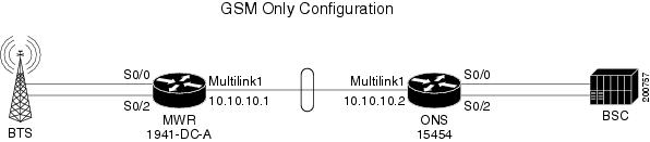
The standard GSM topology includes one or more shorthaul interface connections from the BTS to a RAN-O device via separate E1/T1 connections. The RAN-O devices are connected back-to-back using a Multilink PPP backhaul connection (two or more E1/T1 connections). At the BSC side, the RAN-O to BSC connectivity is exactly like the BTS to RAN-O connections. In this scenario, only GSM traffic traverses the topology (see Figure B-1). For this example, an MWR 1941-DC-A router is to the left at the BTS side, and the Cisco RAN Service Module is housed in the Cisco ONS 15454 platform at the BSC side.
Figure B-1 GSM Only Configuration
MWR 1941-DC-A (GSM only)
!
card type E1 0 0
card type E1 0 1
!
!
redundancy
mode y-cable
standalone
!
network-clock-participate wic 0
network-clock-participate wic 1
network-clock-participate aim 1
network-clock-select 1 E1 0/1
!
ipran-mib snmp-access inBand
ipran-mib location cellSite
!
!
controller E1 0/0
framing NO-CRC4
clock source internal
channel-group 0 timeslots 1-31
!
controller E1 0/1
channel-group 0 timeslots 1-31
!
controller E1 0/2
framing NO-CRC4
clock source internal
channel-group 0 timeslots 1-31
!
!
class-map match-any llq-class
match ip dscp ef
!
policy-map llq-policy
class llq-class
priority percent 99
class class-default
bandwidth remaining percent 1
queue-limit 45
!
interface Multilink1
ip address 10.10.10.1 255.255.255.252
load-interval 30
no keepalive
no cdp enable
ppp pfc local request
ppp pfc remote apply
ppp acfc local request
ppp acfc remote apply
ppp multilink
ppp multilink interleave
ppp multilink group 1
ppp multilink fragment delay 0 1
ppp multilink multiclass
max-reserved-bandwidth 100
service-policy output llq-policy
hold-queue 50 out
ip rtp header-compression ietf-format
!
!
interface Serial0/0:0
no ip address
encapsulation gsm-abis
gsm-abis local 10.10.10.1 4444
gsm-abis remote 10.10.10.2 4444
gsm-abis set dscp 46
no keepalive
!
interface Serial0/1:0
no ip address
encapsulation ppp
keepalive 1
ppp multilink group 1
max-reserved-bandwidth 100
!
interface Serial0/2:0
no ip address
encapsulation gsm-abis
gsm-abis local 10.10.10.1 4446
gsm-abis remote 10.10.10.2 4446
gsm-abis set dscp 46
no keepalive
!
logging history size 500
logging history debugging
logging trap warnings
snmp-server community public RO
snmp-server queue-length 100
snmp-server enable traps snmp linkdown linkup coldstart warmstart
snmp-server enable traps ipran
snmp-server enable traps syslog
snmp-server trap link ietf
snmp-server ifIndex persist
no snmp-server sparse-table
snmp-server host 64.50.100.254 version 2c V2C
disable-eadi
RAN Service Module (GSM only)
!
version 12.2
service timestamps debug datetime msec localtime
service timestamps log datetime msec localtime
no service password-encryption
service internal
!
hostname Router
!
boot-start-marker
boot-end-marker
!
logging buffered 100000 debugging
!
clock timezone PST -8
ip subnet-zero
ip cef
no ip domain-lookup
!
!
controller E1 1/0
framing NO-CRC4
channel-group 0 timeslots 1-31
!
controller E1 1/1
channel-group 0 timeslots 1-31
!
controller E1 1/2
framing NO-CRC4
channel-group 0 timeslots 1-31
!
controller E1 1/3
!
controller E1 1/4
!
controller E1 1/5
!
controller E1 1/6
!
controller E1 1/7
!
controller E1 1/8
!
controller E1 1/9
!
controller E1 1/10
!
controller E1 1/11
!
controller E1 1/12
!
controller E1 1/13
!
controller E1 1/14
!
controller E1 1/15
!
controller E1 1/16
!
controller E1 1/17
!
controller E1 1/18
!
controller E1 1/19
!
controller E1 1/20
!
controller E1 1/21
!
controller E1 1/22
!
controller E1 1/23
!
controller E1 1/24
!
controller E1 1/25
!
controller E1 1/26
!
controller E1 1/27
!
controller E1 1/28
!
controller E1 1/29
!
controller E1 1/30
!
controller E1 1/31
!
controller E1 1/32
!
controller E1 1/33
!
controller E1 1/34
!
controller E1 1/35
!
controller E1 1/36
!
controller E1 1/37
!
controller E1 1/38
!
controller E1 1/39
!
controller E1 1/40
!
controller E1 1/41
!
controller E1 2/0
!
controller E1 2/1
!
controller E1 2/2
!
controller E1 2/3
!
controller E1 2/4
!
controller E1 2/5
!
controller E1 2/6
!
controller E1 2/7
!
controller E1 2/8
!
controller E1 2/9
!
controller E1 2/10
!
controller E1 2/11
!
controller E1 2/12
!
controller E1 2/13
!
controller E1 2/14
!
controller E1 2/15
!
controller E1 2/16
!
controller E1 2/17
!
controller E1 2/18
!
controller E1 2/19
!
controller E1 2/20
!
controller E1 2/21
!
controller E1 2/22
!
controller E1 2/23
!
controller E1 2/24
!
controller E1 2/25
!
controller E1 2/26
!
controller E1 2/27
!
controller E1 2/28
!
controller E1 2/29
!
controller E1 2/30
!
controller E1 2/31
!
controller E1 2/32
!
controller E1 2/33
!
controller E1 2/34
!
controller E1 2/35
!
controller E1 2/36
!
controller E1 2/37
!
controller E1 2/38
!
controller E1 2/39
!
controller E1 2/40
!
controller E1 2/41
!
controller E1 3/0
!
controller E1 3/1
!
controller E1 3/2
!
controller E1 3/3
!
controller E1 3/4
!
controller E1 3/5
!
controller E1 3/6
!
controller E1 3/7
!
controller E1 3/8
!
controller E1 3/9
!
controller E1 3/10
!
controller E1 3/11
!
controller E1 3/12
!
controller E1 3/13
!
controller E1 3/14
!
controller E1 3/15
!
controller E1 3/16
!
controller E1 3/17
!
controller E1 3/18
!
controller E1 3/19
!
controller E1 3/20
!
controller E1 3/21
!
controller E1 3/22
!
controller E1 3/23
!
controller E1 3/24
!
controller E1 3/25
!
controller E1 3/26
!
controller E1 3/27
!
controller E1 3/28
!
controller E1 3/29
!
controller E1 3/30
!
controller E1 3/31
!
controller E1 3/32
!
controller E1 3/33
!
controller E1 3/34
!
controller E1 3/35
!
controller E1 3/36
!
controller E1 3/37
!
controller E1 3/38
!
controller E1 3/39
!
controller E1 3/40
!
controller E1 3/41
!
!
class-map match-any llq-class
match ip dscp ef
!
!
policy-map llq-policy
class llq-class
priority percent 99
class class-default
bandwidth remaining percent 1
queue-limit 45
!
interface Multilink1
ip address 10.0.0.2 255.255.255.0
ip tcp header-compression ietf-format
load-interval 30
no keepalive
no cdp enable
ppp pfc local request
ppp pfc remote apply
ppp acfc local request
ppp acfc remote apply
ppp multilink
ppp multilink fragment-delay 1
ppp multilink interleave
ppp multilink multiclass
multilink-group 1
max-reserved-bandwidth 100
service-policy output llq-policy
hold-queue 50 out
ip rtp header-compression ietf-format
!
interface ATM0/0
no ip address
loopback line
!
interface GigabitEthernet0/0
no ip address
duplex auto
speed auto
no negotiation auto
!
interface POS0/0
no ip address
loopback line
trigger crc-error delay 0
crc 32
!
interface ATM1/0
no ip address
loopback line
!
interface GigabitEthernet1/0
no ip address
duplex auto
speed auto
negotiation auto
!
interface POS1/0
no ip address
loopback line
crc 32
!
interface Serial1/0:0
no ip address
encapsulation gsm-abis
no keepalive
gsm-abis local 10.0.0.2 4444
gsm-abis remote 10.0.0.1 4444
gsm-abis set dscp ef
!
interface Serial1/1:0
no ip address
encapsulation ppp
keepalive 1
ppp multilink
multilink-group 1
!
interface Serial1/2:0
no ip address
encapsulation gsm-abis
no keepalive
gsm-abis local 10.0.0.2 4446
gsm-abis remote 10.0.0.1 4446
gsm-abis set dscp ef
!
interface ATM2/0
no ip address
loopback line
!
interface GigabitEthernet2/0
no ip address
duplex auto
speed auto
negotiation auto
!
interface POS2/0
no ip address
loopback line
crc 32
!
interface ATM3/0
no ip address
loopback line
!
interface GigabitEthernet3/0
no ip address
duplex auto
speed auto
negotiation auto
!
interface POS3/0
no ip address
loopback line
trigger crc-error threshold 0
trigger crc-error delay 0
crc 32
!
!
ip classless
no ip http server
!
!
tftp-server system:/memory/iosimage alias iosimage
!
!
control-plane
!
!
line con 0
stopbits 1
line vty 0 4
login
!
no scheduler allocate
!
UMTS Only Configuration
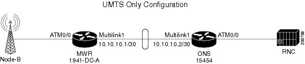
The traditional UMTS configuration is similar to the GSM configuration except only UMTS traffic traverses the topology. Unlike GSM traffic, UMTS traffic arrives at the RAN-O device via ATM PVCs. The UMTS traffic is then routed over the traditional Multilink PPP backhaul connection. At the RNC side, the RAN-O to RNC connectivity is exactly like the Node-B to RAN-O interface connections. Aside from the necessity of ATM connectivity, the physical connectivity for UMTS is exactly like the GSM topology (see Figure B-2). For this example, an MWR 1941-DC-A router is to the left at the Node-B side, and the Cisco RAN Service Module is housed in the Cisco ONS 15454 platform at the RNC side.
Figure B-2 UMTS Only Configuration
MWR 1941-DC-A (UMTS only)
!
card type e1 0 0
card type e1 0 1
card type e1 0 2
card type e1 1 0
!
redundancy
mode y-cable
standalone
!
network-clock-participate slot 1
network-clock-participate wic 0
network-clock-participate wic 1
network-clock-participate wic 2
network-clock-participate aim 1
network-clock-select 1 E1 0/2
!
ipran-mib snmp-access inBand
ipran-mib location cellSite
!
!
controller E1 0/2
channel-group 0 timeslots 1-31
!
controller E1 1/0
mode atm aim 1
clock source internal
!
class-map match-any llq-class
match dscp ef
!
!
policy-map llq-policy
class llq-class
priority percent 99
class class-default
bandwidth remaining percent 1
queue-limit 45
!
!
interface Multilink1
ip address 10.10.10.1 255.255.255.252
load-interval 30
no keepalive
no cdp enable
ppp pfc local request
ppp pfc remote apply
ppp acfc local request
ppp acfc remote apply
ppp multilink
ppp multilink interleave
ppp multilink group 4
ppp multilink fragment delay 0 1
ppp multilink multiclass
max-reserved-bandwidth 100
service-policy output llq-policy
hold-queue 50 out
ip rtp header-compression ietf-format
!
interface FastEthernet0/0
no ip address
duplex auto
speed auto
!
interface FastEthernet0/1
no ip address
duplex auto
speed auto
!
interface Serial0/2:0
no ip address
encapsulation ppp
load-interval 30
no keepalive
ppp multilink
ppp multilink group 1
max-reserved-bandwidth 100
!
interface ATM1/0
no ip address
load-interval 30
scrambling-payload
no atm ilmi-keepalive
atm umts-iub
umts-iub congestion-control
umts-iub backhaul-timer 1
umts-iub set dscp ef
umts-iub set peering dscp ef
no umts-iub backhaul-oam
umts-iub local 10.10.10.1 8100
umts-iub remote 10.10.10.2 8100
pvc 1/15
encapsulation aal0
umts-iub set dscp ef
umts-iub congestion priority protected
!
pvc 1/112 qsaal
umts-iub set dscp ef
!
!
no ip http server
!
snmp-server community public RO
snmp-server ifindex persist
snmp-server trap link ietf
snmp-server queue-length 100
snmp-server enable traps snmp linkdown linkup coldstart warmstart
snmp-server enable traps ipran
snmp-server enable traps syslog
snmp-server host 172.19.23.26 version 2c v2c
!
disable-eadi
RAN Service Module (UMTS only)
There are three separate UMTS examples shown on the following pages:
PVC Mapping Example for UMTS
!
! Last configuration change at 18:19:50 EDT Tue Oct 24 2006
! NVRAM config last updated at 18:19:51 EDT Tue Oct 24 2006
!
version 12.2
service timestamps debug datetime msec localtime
service timestamps log datetime msec localtime
no service password-encryption
service internal
!
hostname Skyla-1
!
boot-start-marker
boot-end-marker
!
logging buffered 100000 debugging
!
!
cross-connect vc4 port 1
connect interface atm 0/0
max vpi-bits 1 vci-bits 6
!
!
cross-connect vc4 port 2
connect interface atm 1/0
max vpi-bits 1 vci-bits 8
!
!
cross-connect vc4 port 3
connect interface atm 2/0
max vpi-bits 1 vci-bits 8
!
!
cross-connect vc4 port 4
connect interface atm 3/0
max vpi-bits 1 vci-bits 8
!
ran-opt atm initialize
clock timezone EST -5
clock summer-time EDT date Apr 2 2006 2:00 Oct 29 2006 2:00
ip subnet-zero
no ip domain-lookup
!
!
ipran-mib snmp-access outOfBand
ipran-mib location aggSite
!
controller E1 1/0
!
controller E1 1/1
channel-group 0 timeslots 1-31
!
controller E1 1/2
!
controller E1 1/3
!
controller E1 1/4
!
controller E1 1/5
!
controller E1 1/6
!
controller E1 1/7
!
controller E1 1/8
!
controller E1 1/9
!
controller E1 1/10
!
controller E1 1/11
!
controller E1 1/12
!
controller E1 1/13
!
controller E1 1/14
!
controller E1 1/15
!
controller E1 1/16
!
controller E1 1/17
!
controller E1 1/18
!
controller E1 1/19
!
controller E1 1/20
!
controller E1 1/21
!
controller E1 1/22
!
controller E1 1/23
!
controller E1 1/24
!
controller E1 1/25
!
controller E1 1/26
!
controller E1 1/27
!
controller E1 1/28
!
controller E1 1/29
!
controller E1 1/30
!
controller E1 1/31
!
controller E1 1/32
!
controller E1 1/33
!
controller E1 1/34
!
controller E1 1/35
!
controller E1 1/36
!
controller E1 1/37
!
controller E1 1/38
!
controller E1 1/39
!
controller E1 1/40
!
controller E1 1/41
!
controller E1 2/0
!
controller E1 2/1
!
controller E1 2/2
!
controller E1 2/3
!
controller E1 2/4
!
controller E1 2/5
!
controller E1 2/6
!
controller E1 2/7
!
controller E1 2/8
!
controller E1 2/9
!
controller E1 2/10
!
controller E1 2/11
!
controller E1 2/12
!
controller E1 2/13
!
controller E1 2/14
!
controller E1 2/15
!
controller E1 2/16
!
controller E1 2/17
!
controller E1 2/18
!
controller E1 2/19
!
controller E1 2/20
!
controller E1 2/21
!
controller E1 2/22
!
controller E1 2/23
!
controller E1 2/24
!
controller E1 2/25
!
controller E1 2/26
!
controller E1 2/27
!
controller E1 2/28
!
controller E1 2/29
!
controller E1 2/30
!
controller E1 2/31
!
controller E1 2/32
!
controller E1 2/33
!
controller E1 2/34
!
controller E1 2/35
!
controller E1 2/36
!
controller E1 2/37
!
controller E1 2/38
!
controller E1 2/39
!
controller E1 2/40
!
controller E1 2/41
!
controller E1 3/0
!
controller E1 3/1
!
controller E1 3/2
!
controller E1 3/3
!
controller E1 3/4
!
controller E1 3/5
!
controller E1 3/6
!
controller E1 3/7
!
controller E1 3/8
!
controller E1 3/9
!
controller E1 3/10
!
controller E1 3/11
!
controller E1 3/12
!
controller E1 3/13
!
controller E1 3/14
!
controller E1 3/15
!
controller E1 3/16
!
controller E1 3/17
!
controller E1 3/18
!
controller E1 3/19
!
controller E1 3/20
!
controller E1 3/21
!
controller E1 3/22
!
controller E1 3/23
!
controller E1 3/24
!
controller E1 3/25
!
controller E1 3/26
!
controller E1 3/27
!
controller E1 3/28
!
controller E1 3/29
!
controller E1 3/30
!
controller E1 3/31
!
controller E1 3/32
!
controller E1 3/33
!
controller E1 3/34
!
controller E1 3/35
!
controller E1 3/36
!
controller E1 3/37
!
controller E1 3/38
!
controller E1 3/39
!
controller E1 3/40
!
controller E1 3/41
!
!
class-map match-any llq-class
match ip dscp ef
!
!
policy-map llq-policy
class llq-class
priority percent 99
class class-default
bandwidth remaining percent 1
queue-limit 45
!
!
!
interface Multilink1
ip address 10.10.10.2 255.255.255.252
ip tcp header-compression ietf-format
load-interval 30
no keepalive
no cdp enable
ppp pfc local request
ppp pfc remote apply
ppp acfc local request
ppp acfc remote apply
ppp multilink
ppp multilink fragment-delay 0 1
ppp multilink interleave
ppp multilink multiclass
multilink-group 1
max-reserved-bandwidth 100
service-policy output llq-policy
hold-queue 50 out
ip rtp header-compression ietf-format
!
interface ATM0/0
no ip address
!
interface GigabitEthernet0/0
no ip address
duplex auto
speed auto
!
interface POS0/0
no ip address
loopback line
crc 32
!
interface ATM1/0
no ip address
load-interval 30
atm umts-iub aggnode
!
interface ATM1/0.1 multipoint
atm umts-iub
pvc 0/15
encapsulation aal0
umts-iub set dscp ef
umts-iub congestion priority protected
umts-iub pvc-map 1/15 <== per pvc mapping
!
pvc 0/112 qsaal
umts-iub set dscp ef
umts-iub pvc-map 1/112 <== per pvc mapping
!
umts-iub congestion-control
umts-iub backhaul-timer 1
umts-iub set dscp ef
umts-iub set peering dscp ef
umts-iub local 10.10.10.2 8100
umts-iub remote 10.10.10.1 8100
!
interface GigabitEthernet1/0
no ip address
duplex auto
speed auto
!
interface POS1/0
no ip address
crc 32
!
!
interface Serial1/1:0
no ip address
encapsulation ppp
load-interval 30
ppp multilink
multilink-group 1
max-reserved-bandwidth 100
!
interface ATM2/0
no ip address
!
interface GigabitEthernet2/0
no ip address
duplex auto
speed auto
!
interface POS2/0
no ip address
loopback line
crc 32
!
interface ATM3/0
no ip address
!
interface GigabitEthernet3/0
no ip address
duplex auto
speed auto
!
interface POS3/0
no ip address
crc 32
!
tftp-server system:/memory/iosimage alias iosimage
snmp-server community public RO
snmp-server ifindex persist
snmp-server trap link ietf
snmp-server queue-length 100
snmp-server enable traps snmp linkdown linkup coldstart warmstart
snmp-server enable traps ipran
snmp-server host 172.19.23.26 version 2c v2c
!
!
control-plane
!
!
line con 0
exec-timeout 0 0
stopbits 1
line vty 0 4
exec-timeout 0 0
password otbu+1
login
!
no scheduler allocate
!
Profile Example for UMTS
!
version 12.2
service timestamps debug datetime msec localtime
service timestamps log datetime msec localtime
no service password-encryption
service internal
!
hostname Skyla-1
!
boot-start-marker
boot-end-marker
!
logging buffered 100000 debugging
!
!
cross-connect vc4 port 1
connect interface atm 0/0
max vpi-bits 1 vci-bits 6
!
!
cross-connect vc4 port 2
connect interface atm 1/0
max vpi-bits 1 vci-bits 8
!
!
cross-connect vc4 port 3
connect interface atm 2/0
max vpi-bits 1 vci-bits 8
!
!
cross-connect vc4 port 4
connect interface atm 3/0
max vpi-bits 1 vci-bits 8
!
ran-opt atm initialize
clock timezone EST -5
clock summer-time EDT date Apr 2 2006 2:00 Oct 29 2006 2:00
ip subnet-zero
no ip domain-lookup
!
!
umts-profile profile_ATM1/0.1 <== define profile
pvc cisco1 1/15
pvc cisco2 1/112
!
ipran-mib snmp-access outOfBand
ipran-mib location aggSite
!
controller E1 1/0
!
controller E1 1/1
channel-group 0 timeslots 1-31
!
controller E1 1/2
!
controller E1 1/3
!
controller E1 1/4
!
controller E1 1/5
!
controller E1 1/6
!
controller E1 1/7
!
controller E1 1/8
!
controller E1 1/9
!
controller E1 1/10
!
controller E1 1/11
!
controller E1 1/12
!
controller E1 1/13
!
controller E1 1/14
!
controller E1 1/15
!
controller E1 1/16
!
controller E1 1/17
!
controller E1 1/18
!
controller E1 1/19
!
controller E1 1/20
!
controller E1 1/21
!
controller E1 1/22
!
controller E1 1/23
!
controller E1 1/24
!
controller E1 1/25
!
controller E1 1/26
!
controller E1 1/27
!
controller E1 1/28
!
controller E1 1/29
!
controller E1 1/30
!
controller E1 1/31
!
controller E1 1/32
!
controller E1 1/33
!
controller E1 1/34
!
controller E1 1/35
!
controller E1 1/36
!
controller E1 1/37
!
controller E1 1/38
!
controller E1 1/39
!
controller E1 1/40
!
controller E1 1/41
!
controller E1 2/0
!
controller E1 2/1
!
controller E1 2/2
!
controller E1 2/3
!
controller E1 2/4
!
controller E1 2/5
!
controller E1 2/6
!
controller E1 2/7
!
controller E1 2/8
!
controller E1 2/9
!
controller E1 2/10
!
controller E1 2/11
!
controller E1 2/12
!
controller E1 2/13
!
controller E1 2/14
!
controller E1 2/15
!
controller E1 2/16
!
controller E1 2/17
!
controller E1 2/18
!
controller E1 2/19
!
controller E1 2/20
!
controller E1 2/21
!
controller E1 2/22
!
controller E1 2/23
!
controller E1 2/24
!
controller E1 2/25
!
controller E1 2/26
!
controller E1 2/27
!
controller E1 2/28
!
controller E1 2/29
!
controller E1 2/30
!
controller E1 2/31
!
controller E1 2/32
!
controller E1 2/33
!
controller E1 2/34
!
controller E1 2/35
!
controller E1 2/36
!
controller E1 2/37
!
controller E1 2/38
!
controller E1 2/39
!
controller E1 2/40
!
controller E1 2/41
!
controller E1 3/0
!
controller E1 3/1
!
controller E1 3/2
!
controller E1 3/3
!
controller E1 3/4
!
controller E1 3/5
!
controller E1 3/6
!
controller E1 3/7
!
controller E1 3/8
!
controller E1 3/9
!
controller E1 3/10
!
controller E1 3/11
!
controller E1 3/12
!
controller E1 3/13
!
controller E1 3/14
!
controller E1 3/15
!
controller E1 3/16
!
controller E1 3/17
!
controller E1 3/18
!
controller E1 3/19
!
controller E1 3/20
!
controller E1 3/21
!
controller E1 3/22
!
controller E1 3/23
!
controller E1 3/24
!
controller E1 3/25
!
controller E1 3/26
!
controller E1 3/27
!
controller E1 3/28
!
controller E1 3/29
!
controller E1 3/30
!
controller E1 3/31
!
controller E1 3/32
!
controller E1 3/33
!
controller E1 3/34
!
controller E1 3/35
!
controller E1 3/36
!
controller E1 3/37
!
controller E1 3/38
!
controller E1 3/39
!
controller E1 3/40
!
controller E1 3/41
!
!
class-map match-any llq-class
match ip dscp ef
!
!
policy-map llq-policy
class llq-class
priority percent 99
class class-default
bandwidth remaining percent 1
queue-limit 45
!
!
!
interface Multilink1
ip address 10.10.10.2 255.255.255.252
ip tcp header-compression ietf-format
load-interval 30
no keepalive
no cdp enable
ppp pfc local request
ppp pfc remote apply
ppp acfc local request
ppp acfc remote apply
ppp multilink
ppp multilink fragment-delay 0 1
ppp multilink interleave
ppp multilink multiclass
multilink-group 1
max-reserved-bandwidth 100
service-policy output llq-policy
hold-queue 50 out
ip rtp header-compression ietf-format
!
interface ATM0/0
no ip address
!
interface GigabitEthernet0/0
no ip address
duplex auto
speed auto
!
interface POS0/0
no ip address
loopback line
crc 32
!
interface ATM1/0
no ip address
load-interval 30
atm umts-iub aggnode
!
interface ATM1/0.1 multipoint
atm umts-iub
pvc 0/15
encapsulation aal0
umts-iub set dscp ef
umts-iub congestion priority protected
umts-iub name cisco1 <== apply profile
!
pvc 0/112 qsaal
umts-iub set dscp ef
umts-iub name cisco2 <== apply profile
!
umts-iub profile profile_ATM1/0.1 <== apply profile
umts-iub congestion-control
umts-iub backhaul-timer 1
umts-iub set dscp ef
umts-iub set peering dscp ef
umts-iub local 10.10.10.2 8100
umts-iub remote 10.10.10.1 8100
!
interface GigabitEthernet1/0
no ip address
duplex auto
speed auto
!
interface POS1/0
no ip address
crc 32
!
!
interface Serial1/1:0
no ip address
encapsulation ppp
load-interval 30
ppp multilink
multilink-group 1
max-reserved-bandwidth 100
!
interface ATM2/0
no ip address
!
interface GigabitEthernet2/0
no ip address
duplex auto
speed auto
!
interface POS2/0
no ip address
loopback line
crc 32
!
interface ATM3/0
no ip address
!
interface GigabitEthernet3/0
no ip address
duplex auto
speed auto
!
interface POS3/0
no ip address
crc 32
!
tftp-server system:/memory/iosimage alias iosimage
snmp-server community public RO
snmp-server ifindex persist
snmp-server trap link ietf
snmp-server queue-length 100
snmp-server enable traps snmp linkdown linkup coldstart warmstart
snmp-server enable traps ipran
snmp-server host 172.19.23.26 version 2c v2c
!
!
control-plane
!
!
line con 0
exec-timeout 0 0
stopbits 1
line vty 0 4
exec-timeout 0 0
password otbu+1
login
!
no scheduler allocate
!
VPI Mapping Example for UMTS
!
version 12.2
service timestamps debug datetime msec localtime
service timestamps log datetime msec localtime
no service password-encryption
service internal
!
hostname Skyla-1
!
boot-start-marker
boot-end-marker
!
logging buffered 100000 debugging
!
!
cross-connect vc4 port 1
connect interface atm 0/0
max vpi-bits 1 vci-bits 6
!
!
cross-connect vc4 port 2
connect interface atm 1/0
max vpi-bits 1 vci-bits 8
!
!
cross-connect vc4 port 3
connect interface atm 2/0
max vpi-bits 1 vci-bits 8
!
!
cross-connect vc4 port 4
connect interface atm 3/0
max vpi-bits 1 vci-bits 8
!
ran-opt atm initialize
clock timezone EST -5
clock summer-time EDT date Apr 2 2006 2:00 Oct 29 2006 2:00
ip subnet-zero
no ip domain-lookup
!
!
ipran-mib snmp-access outOfBand
ipran-mib location aggSite
!
controller E1 1/0
!
controller E1 1/1
channel-group 0 timeslots 1-31
!
controller E1 1/2
!
controller E1 1/3
!
controller E1 1/4
!
controller E1 1/5
!
controller E1 1/6
!
controller E1 1/7
!
controller E1 1/8
!
controller E1 1/9
!
controller E1 1/10
!
controller E1 1/11
!
controller E1 1/12
!
controller E1 1/13
!
controller E1 1/14
!
controller E1 1/15
!
controller E1 1/16
!
controller E1 1/17
!
controller E1 1/18
!
controller E1 1/19
!
controller E1 1/20
!
controller E1 1/21
!
controller E1 1/22
!
controller E1 1/23
!
controller E1 1/24
!
controller E1 1/25
!
controller E1 1/26
!
controller E1 1/27
!
controller E1 1/28
!
controller E1 1/29
!
controller E1 1/30
!
controller E1 1/31
!
controller E1 1/32
!
controller E1 1/33
!
controller E1 1/34
!
controller E1 1/35
!
controller E1 1/36
!
controller E1 1/37
!
controller E1 1/38
!
controller E1 1/39
!
controller E1 1/40
!
controller E1 1/41
!
controller E1 2/0
!
controller E1 2/1
!
controller E1 2/2
!
controller E1 2/3
!
controller E1 2/4
!
controller E1 2/5
!
controller E1 2/6
!
controller E1 2/7
!
controller E1 2/8
!
controller E1 2/9
!
controller E1 2/10
!
controller E1 2/11
!
controller E1 2/12
!
controller E1 2/13
!
controller E1 2/14
!
controller E1 2/15
!
controller E1 2/16
!
controller E1 2/17
!
controller E1 2/18
!
controller E1 2/19
!
controller E1 2/20
!
controller E1 2/21
!
controller E1 2/22
!
controller E1 2/23
!
controller E1 2/24
!
controller E1 2/25
!
controller E1 2/26
!
controller E1 2/27
!
controller E1 2/28
!
controller E1 2/29
!
controller E1 2/30
!
controller E1 2/31
!
controller E1 2/32
!
controller E1 2/33
!
controller E1 2/34
!
controller E1 2/35
!
controller E1 2/36
!
controller E1 2/37
!
controller E1 2/38
!
controller E1 2/39
!
controller E1 2/40
!
controller E1 2/41
!
controller E1 3/0
!
controller E1 3/1
!
controller E1 3/2
!
controller E1 3/3
!
controller E1 3/4
!
controller E1 3/5
!
controller E1 3/6
!
controller E1 3/7
!
controller E1 3/8
!
controller E1 3/9
!
controller E1 3/10
!
controller E1 3/11
!
controller E1 3/12
!
controller E1 3/13
!
controller E1 3/14
!
controller E1 3/15
!
controller E1 3/16
!
controller E1 3/17
!
controller E1 3/18
!
controller E1 3/19
!
controller E1 3/20
!
controller E1 3/21
!
controller E1 3/22
!
controller E1 3/23
!
controller E1 3/24
!
controller E1 3/25
!
controller E1 3/26
!
controller E1 3/27
!
controller E1 3/28
!
controller E1 3/29
!
controller E1 3/30
!
controller E1 3/31
!
controller E1 3/32
!
controller E1 3/33
!
controller E1 3/34
!
controller E1 3/35
!
controller E1 3/36
!
controller E1 3/37
!
controller E1 3/38
!
controller E1 3/39
!
controller E1 3/40
!
controller E1 3/41
!
!
class-map match-any llq-class
match ip dscp ef
!
!
policy-map llq-policy
class llq-class
priority percent 99
class class-default
bandwidth remaining percent 1
queue-limit 45
!
!
!
interface Multilink1
ip address 10.10.10.2 255.255.255.252
ip tcp header-compression ietf-format
load-interval 30
no keepalive
no cdp enable
ppp pfc local request
ppp pfc remote apply
ppp acfc local request
ppp acfc remote apply
ppp multilink
ppp multilink fragment-delay 0 1
ppp multilink interleave
ppp multilink multiclass
multilink-group 1
max-reserved-bandwidth 100
service-policy output llq-policy
hold-queue 50 out
ip rtp header-compression ietf-format
!
interface ATM0/0
no ip address
!
interface GigabitEthernet0/0
no ip address
duplex auto
speed auto
!
interface POS0/0
no ip address
loopback line
crc 32
!
interface ATM1/0
no ip address
load-interval 30
atm umts-iub aggnode
!
interface ATM1/0.1 multipoint
atm umts-iub
pvc 0/15
encapsulation aal0
umts-iub set dscp ef
umts-iub congestion priority protected
!
pvc 0/112 qsaal
umts-iub set dscp ef
!
umts-iub vpi-map 0 1 <== vpi map
umts-iub congestion-control
umts-iub backhaul-timer 1
umts-iub set dscp ef
umts-iub set peering dscp ef
umts-iub local 10.10.10.2 8100
umts-iub remote 10.10.10.1 8100
!
interface GigabitEthernet1/0
no ip address
duplex auto
speed auto
!
interface POS1/0
no ip address
crc 32
!
interface Serial1/1:0
no ip address
encapsulation ppp
load-interval 30
ppp multilink
multilink-group 1
max-reserved-bandwidth 100
!
interface ATM2/0
no ip address
!
interface GigabitEthernet2/0
no ip address
duplex auto
speed auto
!
interface POS2/0
no ip address
loopback line
crc 32
!
interface ATM3/0
no ip address
!
interface GigabitEthernet3/0
no ip address
duplex auto
speed auto
!
interface POS3/0
no ip address
crc 32
!
tftp-server system:/memory/iosimage alias iosimage
snmp-server community public RO
snmp-server ifindex persist
snmp-server trap link ietf
snmp-server queue-length 100
snmp-server enable traps snmp linkdown linkup coldstart warmstart
snmp-server enable traps ipran
snmp-server host 172.19.23.26 version 2c v2c
!
!
control-plane
!
!
line con 0
exec-timeout 0 0
stopbits 1
line vty 0 4
exec-timeout 0 0
password otbu+1
login
!
no scheduler allocate
!
Combined GSM and UMTS
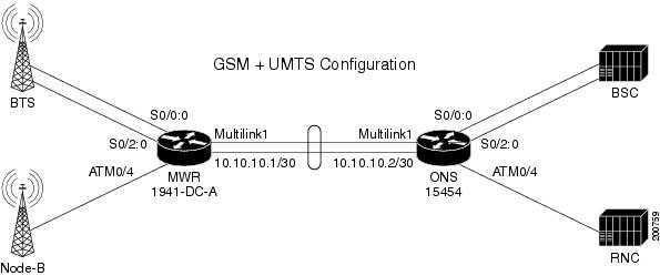
The combined GSM and UMTS configuration allows both the GSM and UMTS technologies to become aggregated over the traditional multilink backhaul connection (see Figure B-3). For this example, an MWR 1941-DC-A router is to the left at the Node-B side, and the Cisco RAN Service Module is housed in the Cisco ONS 15454 platform at the RNC side.
Figure B-3 Combined GSM and UMTS Configuration
MWR 1941-DC-A
!
card type e1 0 0
card type e1 0 1
card type e1 0 2
card type e1 1 0
!
redundancy
mode y-cable
standalone
!
network-clock-participate slot 1
network-clock-participate wic 0
network-clock-participate wic 1
network-clock-participate wic 2
network-clock-participate aim 1
network-clock-select 1 E1 0/2
!
ipran-mib snmp-access inBand
ipran-mib location cellSite
!
!
controller E1 0/0
framing NO-CRC4
clock source internal
channel-group 0 timeslots 1-31
!
controller E1 0/1
channel-group 0 timeslots 1-31
!
controller E1 0/2
framing NO-CRC4
clock source internal
channel-group 0 timeslots 1-31
!
controller E1 0/3
channel-group 0 timeslots 1-31
!
controller E1 1/0
mode atm aim 1
clock source internal
!
class-map match-any llq-class
match dscp ef
!
!
policy-map llq-policy
class llq-class
priority percent 99
class class-default
bandwidth remaining percent 1
queue-limit 45
!
!
interface Multilink1
ip address 10.10.10.1 255.255.255.252
load-interval 30
no keepalive
no cdp enable
ppp pfc local request
ppp pfc remote apply
ppp acfc local request
ppp acfc remote apply
ppp multilink
ppp multilink interleave
ppp multilink group 4
ppp multilink fragment delay 0 1
ppp multilink multiclass
max-reserved-bandwidth 100
service-policy output llq-policy
hold-queue 50 out
ip rtp header-compression ietf-format
!
interface FastEthernet0/0
no ip address
duplex auto
speed auto
!
interface FastEthernet0/1
no ip address
duplex auto
speed auto
!
interface Serial0/0:0
no ip address
encapsulation gsm-abis
gsm-abis local 10.0.0.1 4444
gsm-abis remote 10.0.0.2 4444
gsm-abis set dscp ef
!
interface Serial0/1:0
no ip address
encapsulation ppp
keepalive 1
ppp multilink group 1
max-reserved-bandwidth 100
!
interface Serial0/2:0
no ip address
encapsulation gsm-abis
gsm-abis local 10.0.0.1 4446
gsm-abis remote 10.0.0.2 4446
gsm-abis set dscp ef
!
interface Serial0/3:0
no ip address
encapsulation ppp
keepalive 1
ppp multilink group 1
max-reserved-bandwidth 100
!
interface ATM1/0
no ip address
load-interval 30
scrambling-payload
no atm ilmi-keepalive
atm umts-iub
umts-iub congestion-control
umts-iub backhaul-timer 1
umts-iub set dscp ef
umts-iub set peering dscp ef
no umts-iub backhaul-oam
umts-iub local 10.10.10.1 8100
umts-iub remote 10.10.10.2 8100
pvc 1/15
encapsulation aal0
umts-iub set dscp ef
umts-iub congestion priority protected
!
pvc 1/112 qsaal
umts-iub set dscp ef
!
!!
!
no ip http server
!
snmp-server community public RO
snmp-server ifindex persist
snmp-server trap link ietf
snmp-server queue-length 100
snmp-server enable traps snmp linkdown linkup coldstart warmstart
snmp-server enable traps ipran
snmp-server enable traps syslog
snmp-server host 172.19.23.26 version 2c v2c
!
disable-eadi
RAN Service Module (GSM and UMTS)
!
version 12.2
service timestamps debug datetime msec localtime
service timestamps log datetime msec localtime
no service password-encryption
service internal
!
hostname Skyla-1
!
boot-start-marker
boot-end-marker
!
logging buffered 100000 debugging
!
!
cross-connect vc4 port 1
connect interface atm 0/0
max vpi-bits 1 vci-bits 6
!
!
cross-connect vc4 port 2
connect interface atm 1/0
max vpi-bits 1 vci-bits 8
!
!
cross-connect vc4 port 3
connect interface atm 2/0
max vpi-bits 1 vci-bits 8
!
!
cross-connect vc4 port 4
connect interface atm 3/0
max vpi-bits 1 vci-bits 8
!
ran-opt atm initialize
clock timezone EST -5
clock summer-time EDT date Apr 2 2006 2:00 Oct 29 2006 2:00
ip subnet-zero
no ip domain-lookup
!
!
umts-profile profile_ATM1/0.1
pvc cisco1 1/15
pvc cisco2 1/112
!
ipran-mib snmp-access outOfBand
ipran-mib location aggSite
!
controller E1 1/0
framing NO-CRC4
channel-group 0 timeslots 1-31
!
controller E1 1/1
channel-group 0 timeslots 1-31
!
controller E1 1/2
framing NO-CRC4
channel-group 0 timeslots 1-31
controller E1 1/3
channel-group 0 timeslots 1-31
!
controller E1 1/4
!
controller E1 1/5
!
controller E1 1/6
!
controller E1 1/7
!
controller E1 1/8
!
controller E1 1/9
!
controller E1 1/10
!
controller E1 1/11
!
controller E1 1/12
!
controller E1 1/13
!
controller E1 1/14
!
controller E1 1/15
!
controller E1 1/16
!
controller E1 1/17
!
controller E1 1/18
!
controller E1 1/19
!
controller E1 1/20
!
controller E1 1/21
!
controller E1 1/22
!
controller E1 1/23
!
controller E1 1/24
!
controller E1 1/25
!
controller E1 1/26
!
controller E1 1/27
!
controller E1 1/28
!
controller E1 1/29
!
controller E1 1/30
!
controller E1 1/31
!
controller E1 1/32
!
controller E1 1/33
!
controller E1 1/34
!
controller E1 1/35
!
controller E1 1/36
!
controller E1 1/37
!
controller E1 1/38
!
controller E1 1/39
!
controller E1 1/40
!
controller E1 1/41
!
controller E1 2/0
!
controller E1 2/1
!
controller E1 2/2
!
controller E1 2/3
!
controller E1 2/4
!
controller E1 2/5
!
controller E1 2/6
!
controller E1 2/7
!
controller E1 2/8
!
controller E1 2/9
!
controller E1 2/10
!
controller E1 2/11
!
controller E1 2/12
!
controller E1 2/13
!
controller E1 2/14
!
controller E1 2/15
!
controller E1 2/16
!
controller E1 2/17
!
controller E1 2/18
!
controller E1 2/19
!
controller E1 2/20
!
controller E1 2/21
!
controller E1 2/22
!
controller E1 2/23
!
controller E1 2/24
!
controller E1 2/25
!
controller E1 2/26
!
controller E1 2/27
!
controller E1 2/28
!
controller E1 2/29
!
controller E1 2/30
!
controller E1 2/31
!
controller E1 2/32
!
controller E1 2/33
!
controller E1 2/34
!
controller E1 2/35
!
controller E1 2/36
!
controller E1 2/37
!
controller E1 2/38
!
controller E1 2/39
!
controller E1 2/40
!
controller E1 2/41
!
controller E1 3/0
!
controller E1 3/1
!
controller E1 3/2
!
controller E1 3/3
!
controller E1 3/4
!
controller E1 3/5
!
controller E1 3/6
!
controller E1 3/7
!
controller E1 3/8
!
controller E1 3/9
!
controller E1 3/10
!
controller E1 3/11
!
controller E1 3/12
!
controller E1 3/13
!
controller E1 3/14
!
controller E1 3/15
!
controller E1 3/16
!
controller E1 3/17
!
controller E1 3/18
!
controller E1 3/19
!
controller E1 3/20
!
controller E1 3/21
!
controller E1 3/22
!
controller E1 3/23
!
controller E1 3/24
!
controller E1 3/25
!
controller E1 3/26
!
controller E1 3/27
!
controller E1 3/28
!
controller E1 3/29
!
controller E1 3/30
!
controller E1 3/31
!
controller E1 3/32
!
controller E1 3/33
!
controller E1 3/34
!
controller E1 3/35
!
controller E1 3/36
!
controller E1 3/37
!
controller E1 3/38
!
controller E1 3/39
!
controller E1 3/40
!
controller E1 3/41
!
!
class-map match-any llq-class
match ip dscp ef
!
!
policy-map llq-policy
class llq-class
priority percent 99
class class-default
bandwidth remaining percent 1
queue-limit 45
!
!
!
interface Multilink1
ip address 10.10.10.2 255.255.255.252
ip tcp header-compression ietf-format
load-interval 30
no keepalive
no cdp enable
ppp pfc local request
ppp pfc remote apply
ppp acfc local request
ppp acfc remote apply
ppp multilink
ppp multilink fragment-delay 0 1
ppp multilink interleave
ppp multilink multiclass
multilink-group 1
max-reserved-bandwidth 100
service-policy output llq-policy
hold-queue 50 out
ip rtp header-compression ietf-format
!
interface ATM0/0
no ip address
!
interface GigabitEthernet0/0
no ip address
duplex auto
speed auto
!
interface POS0/0
no ip address
loopback line
crc 32
!
interface ATM1/0
no ip address
load-interval 30
atm umts-iub aggnode
!
interface ATM1/0.1 multipoint
atm umts-iub
pvc 0/15
encapsulation aal0
umts-iub set dscp ef
umts-iub congestion priority protected
umts-iub name cisco1
!
pvc 0/112 qsaal
umts-iub set dscp ef
umts-iub name cisco2
!
umts-iub profile profile_ATM1/0.1
umts-iub congestion-control
umts-iub backhaul-timer 1
umts-iub set dscp ef
umts-iub set peering dscp ef
umts-iub local 10.10.10.2 8100
umts-iub remote 10.10.10.1 8100
!
interface GigabitEthernet1/0
no ip address
duplex auto
speed auto
!
interface POS1/0
no ip address
crc 32
!
interface Serial1/0:0
no ip address
encapsulation gsm-abis
no keepalive
gsm-abis local 10.0.0.2 4444
gsm-abis remote 10.0.0.1 4444
gsm-abis set dscp ef
!
interface Serial1/1:0
no ip address
encapsulation ppp
keepalive 1
ppp multilink
multilink-group 1
!
interface Serial1/2:0
no ip address
encapsulation gsm-abis
no keepalive
gsm-abis local 10.0.0.2 4446
gsm-abis remote 10.0.0.1 4446
gsm-abis set dscp ef
!
interface Serial1/3:0
no ip address
encapsulation ppp
load-interval 30
ppp multilink
multilink-group 1
max-reserved-bandwidth 100
!
interface ATM2/0
no ip address
!
interface GigabitEthernet2/0
no ip address
duplex auto
speed auto
!
interface POS2/0
no ip address
loopback line
crc 32
!
interface ATM3/0
no ip address
!
interface GigabitEthernet3/0
no ip address
duplex auto
speed auto
!
interface POS3/0
no ip address
crc 32
!
tftp-server system:/memory/iosimage alias iosimage
snmp-server community public RO
snmp-server ifindex persist
snmp-server trap link ietf
snmp-server queue-length 100
snmp-server enable traps snmp linkdown linkup coldstart warmstart
snmp-server enable traps ipran
snmp-server host 172.19.23.26 version 2c v2c
!
!
control-plane
!
!
line con 0
exec-timeout 0 0
stopbits 1
line vty 0 4
exec-timeout 0 0
password otbu+1
login
!
no scheduler allocate
!
 Feedback