Base Station Client Utility
Available Languages
Table Of Contents
Information You Need For Configuration
Load New Firmware into Base Station
Base Station Client Utility
This chapter provides a general introduction to the Cisco Aironet Base Station Client Utility (BSCU) and describes the installation, screens, and options.
Here's what you'll find in this chapter:
•
Client Pull-Down Menu Options
Overview
The Cisco Aironet Base Station Client Utility (BSCU) simplifies the configuration and setup of the base station and the associated Cisco Aironet IEEE 802.11 DSSS client radio card (hereafter refered to as the client radio card) in the wireless PC. With the utility, you can configure and upgrade firmware on the client radio card, configure and upgrade firmware in the base station, perform diagnostic tests on the wireless network, and view current status and statistics of the client card.

Caution
Requirements
The BSCU requires an installed Cisco Aironet client radio card in a PC running one of the following operating systems:
•

Note
•
•
•
•
Information You Need For Configuration
The base station is configured from a wireless PC with a client radio card. For wireless devices to establish initial communications with the base station, certain parameters must be set on the wireless devices and the base station. For proper operation, parameters in the base station must match the ISP settings.
Before configuring the base station, gather the following information (your network administrator or ISP should be able to provide any missing information):
•
•
•
•
•
•
•
•
Note
•
•
•
•
•
•
•
•
•
•
•
•
•
•
•
•
•
•
•
•
•
•
•
•
•
•
•
•
Configuring the Wireless PC
You can use the BSCU from a wireless PC to set and change the base station's configuration parameters. However, the wireless PC must be properly configured to communicate with the base station. To revise the wireless PC network parameters, refer to "Wireless PC Network Settings," and the Help guides provided by your operating system.
Step 1
•
•
•
BSCU Installation and Setup
The BSCU is installed from the Cisco Aironet 340 Series Base Station CD shipped with the unit. The setup program installs the BSCU and the Base Station Connection Status utility (see Chapter 4).
Note
Follow these steps to install the BSCU:
Step 1
Step 2
Note
Step 3
Note
After the utility is installed, double-click the BSCU icon located on the computer desktop to activate the utility. The BSCU main screen is shown in .
Figure 2-1

BSCU Main Screen
The main screen provides a status line and the time on the bottom of the screen. The status line indicates whether the client radio card is associated or not. When it is associated, the status line indicates the base station name and the IP address where it is associated. If the client radio card is unable to obtain the IP address from the base station, the base station MAC address is displayed.
The main screen contains four pull-down menu options:
•
•
•
•
When initially setting up or changing base station parameters, use the Base Station tab. From this tab, you can configure the base station parameters and the BSCU will automatically configure the client radio card to match your settings.
After you set up or change the base station parameters, use the Client tab in all the other wireless PCs to configure their client radio cards to match your new base station settings.
Client Pull-Down Menu Options
The Client pull-down menu (see ) specifies several options that are associated with the client radio card in the PC. Table 2-1 describes the pull-down menu options.
Figure 2-2 Client Pull-Down Menu Screen
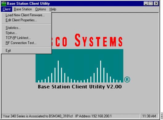
Table 2-1 Client Pull-Down Menu Options
Load New Client Firmware
Loads new firmware into the client radio card. (see page 8)
Edit Client Properties
Sets client radio card parameters. (see page 8)
Statistics
Shows the current receive and transmit statistics of the client radio card. (see page 13)
Status
Shows the current setting and status of the client radio card, including firmware version number, data rate, output power, frequency, association status, and more. (see page 16)
TCP/IP Linktest
Uses the Windows TCP/IP protocol to perform a link test on the wireless network and provides an overall link quality rating. (see page 18)
RF Connection Test
Supports active and passive modes. In passive mode, the current status is read from the client radio card every second. In active mode, the current status is obtained using data packets sent to and received from a specified destination device. (see page 20)
Load New Client Firmware
This option loads new firmware into the client radio card located in the wireless PC running BSCU. When you select this option, an Open dialog box appears that helps you locate or specify the desired new firmware image file (similar to filename.img).
After you specify the firmware image file, the client radio card's firmware is updated and a completion status is displayed.
Caution
Edit Client Properties
This option helps you verify or change the parameter settings for the client radio card in the wireless PC. The Wireless Client Network Parameters screen (see ) appears when the Edit Client Properties option is selected. Table 2-2 describes the screen parameters and indicates how to change the values. Table 2-3 describes the buttons on the bottom of the screen.
Figure 2-3 Wireless Client Network Parameters Screen
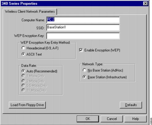
The Computer Name shown on the screen is the name used by your Microsoft operating system to identify your computer on the wired network. This name is also used to identify your wireless PC on the wireless network. This name must be unique for each wireless PCs.
Caution
Note
Note
Table 2-2 Wireless Client Network Parameters
Computer Name
The name assigned to the wireless PC and used to identify the PC on the wireless and wired networks. All computer names on a network must be unique.
To change this value, enter a new name in the entry box.
Range: 1 to 16 ASCII characters
Default: Operating system's Network paremeter setting
SSID
Identifies the base station's radio network and must be used by all wireless devices communicating with the base station.
To change this value, enter a new name in the entry box.
Range: 1 to 32 ASCII characters
Default: tsunami
WEP Encryption Key Entry Method
Selects the encryption key entry method.
Range: Hexadecimal (0-9, A-F) or ASCII Text
Default: Hexadecimal (0-9, A-F)
WEP Encryption Key
Used with 128-bit encryption to provide security. The encryption key used must be set up exactly the same on all wireless devices and the base station. On enterprise wireless devices the encryption key corresponds to the WEP key.
To change the key, enter a new encryption key in the entry box.
Note
Note
(For extra information see WEP Key Conversion.)
Range: ASCII entry—1 to 13 ASCII characters
Hex entry—1 to 26 characters using 0 to 9 and A to F.
Default: 30313233343536373839303132—Hex entry
Note
Data Rate
Specifies the data rate used to communicate with the base station. For the home wireless network this option cannot be changed.
Default: Auto
Enable Encryption (WEP)
Enables or disables the use of 128-bit encryption. A check mark in the selection box indicates WEP Encryption is enabled, and a blank box indicates WEP Encryption is disabled.
To change this option, click in the selection box.
Note
Range: Enabled or Disabled
Default: 128-bit Encryption Enabled
Network Type
The Base Station (Infrastructure) option indicates the radio card communicates with a base station. The No Base Station (AdHoc) option indicates the radio card uses Ad-Hoc mode to communicate with another wireless device (for additional information refer to the Cisco Aironet Client Utility (ACU) documentation for your client card). To change this option, click the desired selection.
Range: No Base Station (AdHoc) or
Base Station (Infrastructure)
Default: Base Station (Infrastructure)
The base station's default parameters are shown below:
•
•
•
•
•
•
Note
•
•
•
Note
Note
WEP Key Conversion
The BSCU supports two entry methods for the WEP Encryption Key parameter:
•
When using the ASCII option, the BSCU converts each ASCII character into its corresponding 8-bit hexadecimal code value. For example: the entry 1 2 3 4 A B C ! @ # [ is converted into 31 32 33 34 41 42 43 21 40 23 5B 00 00 (spaces added for clarity). In this example, two null characters were inserted to complete the entry.
Note
Note
•
When using the Hexadecimal option, the BSCU converts two entered characters into one 8-bit hexadecimal code. For example: the entry 1 2 3 8 9 0 5 6 A B C D E F 7 is converted into 12 38 90 56 AB CD EF 70 00 00 00 00 00 (spaces added for clarity). In this example, 11 null characters are inserted to complete the entry.
Note
Note
Statistics
The Statistics option provides the current receive and transmit statistics from the client radio card once per second. The 340 Series Statistics screen is shown in :
Figure 2-4 340 Series Statistics Screen
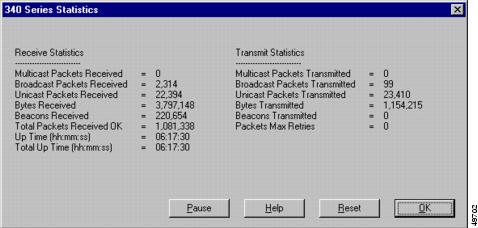
The 340 Series Statistics screen is divided into Receive Statistics and Transmit Statistics. The Receive Statistics area provides information regarding received data packets and beacons (see Table 2-4). The Transmit Statistics area provides information on transmitted data packets and beacons (see Table 2-5). The buttons on the bottom of the 340 Series Statistics screen are defined in Table 2-6.
Status
The 340 Series Status screen (see ) shows the current settings and status of the client radio card, including firmware version number, data rate, output power, frequency, association status, etc. The status information from the radio card is updated once per second. Table 2-7 describes the 340 Series Status screen parameters. Table 2-8 describes the buttons on the bottom of the 340 Series Status screen.
Figure 2-5 340 Series Status Screen
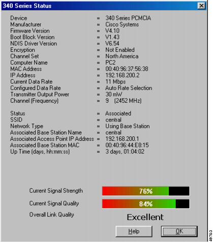
Table 2-8 Buttons on the Status Screen
OK
Exits the screen.
Help
Provides information on the screen and its parameters.
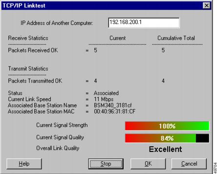
TCP/IP Linktest
This option uses the TCP/IP protocol to perform a link test on the wireless or wired network and provides an overall link quality rating based on the transmitted and received data packets. illustrates the TCP/IP Linktest screen, and Table 2-9 describes the parameters on the screen.
Note
You can use this test to evaluate the performance of the RF link on which the wireless PC is located. The statistics are constantly updated until the test is stopped. The test can be started and stopped as often as desired. Both current and cumulative totals are presented.
Figure 2-6 TCP/IP Linktest Screen
RF Connection Test
The RF Connection Test reads the current status from the client radio card once per second to quickly scan wireless signal strength. This test can be set up for single or continuous operation.
The test has two modes of operation: passive (default) and active. The passive mode does not initiate any RF network traffic but only monitors the RF traffic to provide signal strength, signal quality, and link-speed indications. shows the RF Connection Test screen and illustrates the passive mode parameters being monitored.
The active mode actively sends and receives packets to or from the associated base station and indicates percent complete and percent successful. Active mode is initiated when you change the default test configuration using the Setup button. illustrates the RF Connection Test screen with the active mode test results shown.
If the wireless PC is portable, you can use the active mode to determine the wireless network coverage area by performing the test in various locations.
Table 2-11 describes the parameters on the RF Connection Test screens. Table 2-12 describes the buttons on the bottom of the RF Connection Test screens. shows the RF Connection Test Setup screen. Table 2-13 describes the parameters and indicates how to change them. Table 2-14 describes the buttons on the bottom of the RF Connection Test Setup screen.
Figure 2-7 RF Connection Test Screen - Passive Mode
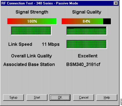
This screen illustrates the default screen of the RF connection test. The results from passive mode operation of the RF connection test indicate the receive side the wireless network is active and operational, but not that the wireless PC can successfully transmit to the base station.
The passive mode operation of the RF connection test does not cause additional loading on the wireless network because it does not transmit messages. This test can be used to provide a quick view of the condition of the wireless network from the wireless PC's location. Typically, when the overall link quality is excellent or good the wireless PC should be able to communicate successfully on the wireless network from the current location.
Figure 2-8 RF Connection Test Screen - Active Mode
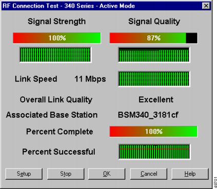
The active mode test is a better indication of the condition of the RF link because messages flow in both directions—to the base station and from the base station.
Table 2-12 Buttons on the RF Connection Test Screen
Setup
Allows the user to change test default parameters (see and Table 2-13).
Start
Initiates a test. When the test is started, the button becomes the Stop button.
Stop
Stops a test that is running. When the test is stopped, the button changes into the Start button.
OK
Terminates the test, resets statistics to zero, and exits the screen.
Cancel
Exits the screen without starting the test.
Help
Provides information on the screen and its parameters
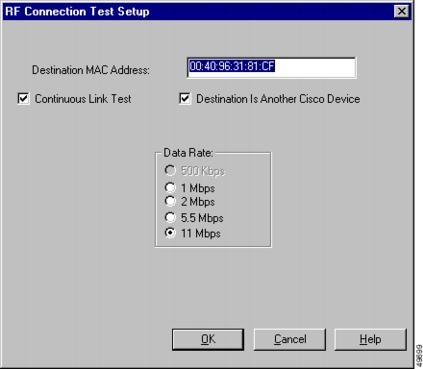
You can use the RF Connection Test Setup screen to change the default settings and enter active mode. In active mode, the test can evaluate the wireless network from the wireless PC's location by transmitting messages and receiving responses.
You can use the Setup screen to specify a base station by entering its MAC address. The test can also be set to operate continuously or to be directed to a wireless device of another manufacturer.
Figure 2-9 RF Connection Test Setup Screen
Base Station Pull-Down Menu
The Base Station pull-down menu allows you to initially configure or change the base station and client radio card settings (see ). Table 2-15 defines the selectable options in the pull-down menu.
Figure 2-10 Base Station Pull-Down Menu

Table 2-15 Base Station Pull-Down Menu Options
Set Up Base Station
You can use this option to set-up the configuration parameters in the base station and the client radio card (see "Set Up Base Station" section).
Load New Firmware Into Base Station
You can use this option to load new firmware into the base station (see "Preferences" section).
Load New Modem Firmware
You can use this option to load new firmware into the base station's optional modem (see "Load New Modem Firmware" section).
Set Up Base Station
The Set Up Base Station option allows you to set up and configure the base station and the client radio card in the wireless PC. When you select this option, the Set Up Base Station With My Settings Screen appears; on it you can view the current base station configuration settings. You can change the settings by clicking Edit Base Station Settings, or you can accept the current settings by clicking OK.
When you click OK to accept the base station settings, the BSCU configures the base station to the settings, then automatically configures the client radio in the wireless PC to the same base station settings.
The configuration parameters displayed on the Set Up Base Station With My Settings Screen depend upon the selected base station mode (connection type). The screen parameter descriptions are provided in the sections on connection properties.
illustrates the base station default parameter settings, and Table 2-16 describes the buttons on the bottom of the screen.
Figure 2-11 Set Up Base Station With My Settings Screen
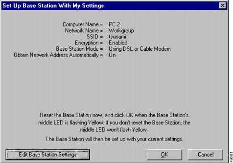
Table 2-16 Buttons on the Setup Base Station With My Settings Screen
Edit Base Station Settings
Allows you to configure the base station radio and operating mode (connection type) parameters (see Base Station Wireless Network Parameters).
OK
Saves parameters and exits the screen.
Cancel
Exits the screen without changing parameters.
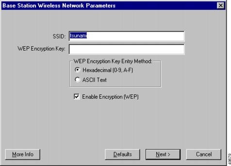
Base Station Wireless Network Parameters
When you click the Edit Base Station Settings button, the Base Station Wireless Network Parameters Screen () displays allowing you to accept or change the SSID, the WEP key entry method, the WEP Encryption Key, and the encryption setting for the base station and client card. When you are satisfied with the parameter settings on the screen, click Next. This saves the base station wireless network configuration parameters and displays the Base Station Properties Screen.
Table 2-17 describes the parameters on the Base Station Wireless Network Parameters Screen, and Table 2-18 describes the buttons on the bottom of the screen.
Figure 2-12 Base Station Wireless Network Parameters Screen
Note
Note
Table 2-17 Base Station Wireless Network Parameters
SSID
Identifies the base station's radio network and must be used by all wireless devices communicating with the base station.
To change this value, enter a new name in the entry box.
Range: 1 to 32 ASCII characters
Default: tsunami
WEP Encryption Key Entry Method
Selects the encryption key entry method. To changes this value, click Hexadecimal (0-9, A-F), or ASCII Text.
Range: Hexadecimal (0-9, A-F) or ASCII Text
Default: Hexadecimal (0-9, A-F)
WEP Encryption Key
Provides security with 128-bit encryption. The encryption key must be set up exactly the same on all wireless devices and the base station. On enterprise wireless devices the encryption key corresponds to the WEP key.
This entry is only available on client radio cards that support 128-bit WEP.
Note
(For additional information see "WEP Key Conversion" section.)
Range: ASCII entry—1 to 13 ASCII characters
Hex entry—1 to 26 characters using 0 to 9 and A to F
Default: 30313233343536373839303132—Hex entry
Note
Enable Encryption (WEP)
Enables or disables the use of 128-bit encryption. A check mark in the selection box indicates WEP Encryption is enabled, and a blank box indicates WEP Encryption is disabled.
To change this option, click in the selection box.
Note
Range: Enabled or Disabled
Default: 128-bit Encryption Enabled
Table 2-18 Buttons on the Base Station Wireless Network Parameters Screen
More Info
Provides information on the screen and its parameters.
Defaults
Sets the base station default values for the parameters (see Base Station Default Parameters).
Next
Saves any changes, and exits the screen (see Base Station Properties).
Cancel
Exits the screen without saving any changes, and returns to the Set Up Base Station With My Settings screen.
Base Station Default Parameters
The base station default parameters are shown below:
•
•
•
•
•
•
Note
•
•
•
Note
Note
WEP Key Conversion
The BSCU supports two entry methods for the WEP Encryption Key parameter:
•
When using ASCII option, the BSCU converts each ASCII character into its corresponding 8-bit hexadecimal code value. For example: the entry 1 2 3 4 A B C ! @ # [ is converted into 31 32 33 34 41 42 43 21 40 23 5B 00 00 (spaces added for clarity). In this example, two null characters were inserted to complete the entry.
Note
Note
•
When using the Hexadecimal option, the BSCU converts two entered characters into one 8-bit hexadecimal code. For example: the entry 0 1 2 3 8 9 0 5 A B C D E F 7 is converted into 01 23 89 05 AB CD EF 70 00 00 00 00 00 (spaces added for clarity). In this example, 11 null characters were inserted to complete the entry.
Note
Note
Base Station Properties
The Base Station Properties Screen allows you to select the following connection type options:
•
•
•
•
Figure 2-13 illustrates the Base Station Properties Screen containing the default connection type (operating mode). Table 2-19 describes the buttons on the bottom of the screen.
Figure 2-13 Base Station Properties Screen

Table 2-19 Buttons on the Base Station Properties Screen
More Info
Provides additional information on the screen parameters.
Back
Returns to the Base Station Wireless Network Properties screen.
Next
Saves parameters and goes to the next screen (see the following connection type descriptions).
Cancel
Exits the screen without changing parameters, and returns to the Set Up Base Station With My Settings Screen.
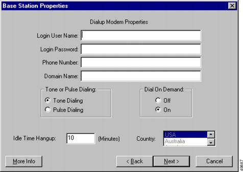
Dial-Up Modem Properties
You can use the dial-up modem option to enter information required to access the dial-up facility for your ISP. shows the Dialup Modem Properties Screen. Table 2-20 describes the dial-up modem properties and how to change the parameters. Table 2-21 describes the buttons on the bottom of the screen.
Caution
Note
Note
Figure 2-14 Dialup Modem Properties Screen
Cable/DSL Modem Properties
With the cable or DSL modem option you can configure a high-speed connection for the base station. You can change the parameters used to access your ISP account, but the parameter values must be obtained from your ISP.
shows the Cable/DSL Modem Properties Screen, and Table 2-22 describes the screen parameters. Follow the instructions in the table to set or change any parameter. When you are satisfied with the parameter settings, click Next.
Table 2-23 describes the manual entry prameters and Table 2-24 describes the buttons on the bottom of the screen.
Figure 2-15 Cable/DSL Modem Properties Screen
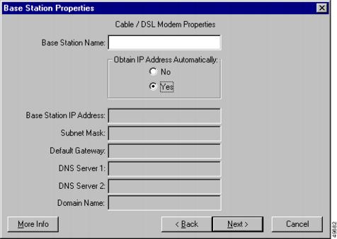
Table 2-22 Cable/DSL Modem Parameters
Base Station Name
Specifies the name used to identify the base station. To change this value, enter a new name in the entry box.
Note
Note
Range: 1 to 16 ASCII characters
Default: BSM340_xxxxxx, or BSE340_xxxxxx
(The xxxxxx denotes the last six digits of the base station MAC address—a unique hardware-based number used to identify the base station on Ethernet links.)
(The BSM denotes the modem option, and the BSE denotes an Ethernet only option.)
Obtain IP Address Automatically
When this entry is set to On, the base station automatically obtains IP address information from a DHCP server. When this entry is set to Off, you must manually enter the network values provided by your ISP (refer to Table 2-23 for manual entry information needed).
To change this field, click On or Off.
Range: On or Off
Default: On
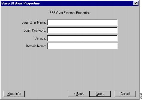
PPP-Over-Ethernet Properties
The PPP-over-Ethernet mode is used when your ISP uses the Point-to-Point Protocol through a cable or DSL modem. You can change the parameters used to access your ISP account, but you must obtain the parameter values from your ISP. Figure 2-16 contains the PPP Over Ethernet Properties screen. Follow the instructions in Table 2-25 to set or change any parameters. Table 2-26 describes the buttons on the bottom of the PPP Over Ethernet Properties screen.
Note
Figure 2-16 PPP Over Ethernet Properties Screen
Access Point Properties
In Access Point mode the base station can connect to an internal wired LAN. In this mode the wireless devices can access the wired LAN for network resources. The Access Point Properties screen is shown in Figure 2-17 and the parameters are listed in Table 2-27; follow the instructions in the table to set or change any parameter. Table 2-28 describes the manual entry prameters and Table 2-29 describes the buttons on the bottom of the Access Point Properties screen.
shows the manual network address fields. The extra network address fields occur when the Obtain IP Address Automatically parameter is set to No. When this parameter is set to Yes, the base station automatically obtains the network address information from an external DHCP server on the wired network.
In Access Point mode the base station does not provide a DHCP server function or a NAT function for the wireless or wired devices. If the wired network contains a DHCP server, the wireless PCs can be set to automatically obtain network information through DHCP when using the radio card. The base station functions as a typical Access Point and pass DHCP packets to or from the DHCP server.
Note
Figure 2-17 Access Point Properties Screen
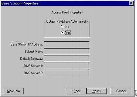
Table 2-27 Access Point Properties Parameters
Obtain IP Address Automatically
When this parameter is set to On, the base station obtains IP address information from an external DHCP server. When this parameter is set to Off, you must manually enter the network information shown in Table 2-28.
To change this parameter, click On or Off.
Range: On or Off
Default: On
See Table 2-28 for manual entry information.
Load New Firmware into Base Station
With the Load New Firmware Into Base Station option you can upgrade the firmware in the base station. A standard Open dialog box appears, allowing you to locate the appropriate base station firmware image file. The image file has a name similar to filename.450. Select the file and then click the Open button. The firmware update progress is indicated by a progress bar showing the percentage complete. When the upgrade is finished, the progress bar indicates 100%.]
Note
You can exit the process without loading new firmware by selecting the Cancel button.
Load New Modem Firmware
With the Load New Modem Firmware option you can upgrade the firmware in the base station modem. A standard Open dialog box appears in which you can locate the appropriate base station modem firmware file. The firmware file has a name similar to filename.MDM. Select the file and then click the Open button. The firmware update progress is indicated by a progress bar showing the percentage complete. When the upgrade is finished, the progress bar indicates 100%
Note
You can exit the process without loading new firmware by clicking the Cancel button.
Options Pull-Down Menu
The Options pull-down menu (see ) allows you to create a floppy disk copy of the configuration information to use when configuring new wireless PCs. Also, it enables you to revise the Status Bar Clock setting to display seconds. Table 2-30 defines the selectable options in the pull-down menu.
Figure 2-18 Options Pull-Down Menu

Table 2-30 Options Pull-Down Menu Selections
Install Additional Computer
You can use this option to save the client radio card configuration parameters to a disk file to set up another wireless PC (see "Install Additional Computer" section).
Preferences
You can use this option to display seconds in the Status Bar Clock (see "Preferences" section).
Install Additional Computer
You can use the Install Additional Computer option to save the client radio card configuration parameters to set up additional wireless PCs with a client radio card. The configuration information is saved to a floppy disk for portability to a new wireless PC when you click Save to Floppy Drive on the bottom of the Install Additional Computer screen.
shows the Install Additional Computer screen and Table 2-31 describes the buttons on the bottom of the screen.
The following configuration information is saved:
•
•
•
•
Figure 2-19 Install Additional Computer Screen
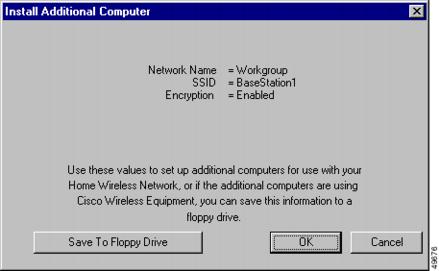
Table 2-31 Buttons on the Install Additional Computer Screen
Save To Floppy Drive
You can use this button to save the client radio card configuration parameters to a floppy disk. The floppy disk can be used to configure a client radio card in another wireless PC (see "Edit Client Properties" section).
OK
Saves parameters and exits the screen.
Cancel
Exits the screen without changing parameters.
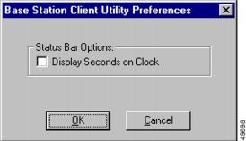
Preferences
With the Preferences option you can display seconds in the Status Bar Clock that appears on the bottom of the Cisco Aironet Base Station Client Utility's main screen (see Figure 2-1). illustrates the Preferences Option screen. To configure the Status Bar Clock to display seconds, click Display Seconds on Clock.
Figure 2-20 Preferences Option Screen
Getting Help
To access information about BSCU, press F1 or select Contents from the Help pull-down menu (see Figure 2-21). An overview of BSCU is displayed.
From the Overview of the Cisco Aironet Base Station Client Utility screen, you can access additional information.
•
•
•
•
•
Figure 2-21
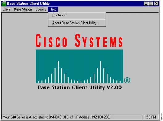
Help Pull-Down Menu Screen
Exiting BSCU
To exit BSCU, select Exit from the Client pull-down menu (see Figure 2-22).
Figure 2-22 Exit Option
 Feedback