- Preface
- Overview of the 1532 Access Point
- Installing the Access Point
- Troubleshooting
- Appendix A Translated Safety Warnings
- Appendix B Declarations of Conformity and Regulatory Information
- Appendix C Channels and Power Levels
- Appendix D Access Point Data Sheet
- Appendix E Access Point Pinouts
- Appendix F Configuring DHCP Option 43
- Glossary
Cisco Aironet 1530 Series Outdoor Access Point Hardware Installation Guide
Bias-Free Language
The documentation set for this product strives to use bias-free language. For the purposes of this documentation set, bias-free is defined as language that does not imply discrimination based on age, disability, gender, racial identity, ethnic identity, sexual orientation, socioeconomic status, and intersectionality. Exceptions may be present in the documentation due to language that is hardcoded in the user interfaces of the product software, language used based on RFP documentation, or language that is used by a referenced third-party product. Learn more about how Cisco is using Inclusive Language.
- Updated:
- July 10, 2019
Chapter: Installing the Access Point
- Unpacking the Access Point
- Tools and Hardware
- Warnings
- Safety Information
- Avoiding Damage to Radios in a Testing Environment
- Installation Guidelines
- Mounting the Access Point
- Installation Options
- Access Point Mounting Orientation
- Wall Mounting the Access Point with the Fixed Mounting Kit
- Pole Mounting the Access Point with the Fixed Mount Kit
- Wall Mounting the Access Point with the Pivoting Mounting Kit
- Pole Mounting the Access Point with the Pivoting Mounting Kit
- Horizontally Mounting the Access Point with Optional Horizontal Mount Plate
- Installing AP Cover or Solar Shield (AIR-ACC1530-CVR=)
- Installing Antennas
- Antenna Configurations
- Antenna N-Type Connector Locations
- Installing a Lightning Arrestor
Installing the Access Point
This chapter describes how to install the 1532 access point and contains the following sections:
Unpacking the Access Point
To unpack the access point, follow these steps:
Step 1![]() Open the shipping container and carefully remove the contents.
Open the shipping container and carefully remove the contents.
Step 2![]() Return all packing materials to the shipping container, and save it.
Return all packing materials to the shipping container, and save it.
Step 3![]() Ensure that all items listed in “Package Contents” are included in the shipment. If any item is damaged or missing, notify your authorized Cisco sales representative.
Ensure that all items listed in “Package Contents” are included in the shipment. If any item is damaged or missing, notify your authorized Cisco sales representative.
Package Contents
Tools and Hardware
The tools and hardware used to install the 1532 access point are described in:
Optional Tools and Hardware
Depending on what you ordered, the following optional equipment may be part of your shipment:
- External antennas, depending on which ones you purchased (see “Antenna Configurations” section for more information).
- Wall/Pole mount bracket, available as an option or a spare (AIR-ACC1530-PMK1[=])
- Wall/Pole mount bracket with tilt mechanism, spare only (AIR-ACC1530-PMK2=)
- AP cover / Solar Shield for 1532, spare only (AIR-ACC1530-CVR=)
- AC/DC power adapter, spare only (AIR-PWRADPT-1530=)
- Spare Parts kit containing extra cable glands, power connector, ground lug, etc. (AIR-ACC1530-KIT1=)
- FIPS kit (AIRLAP-FIPSKIT=)
- Lightning Arrestor kit (AIR-ACC245LA-N=)
Optional Tools and Hardware That You Supply
Tools and materials that are user-supplied are:
- Ground lug crimping tool (Panduit CT-720 with CD-720-1 die)
- 6-AWG copper ground wire
- 10 mm open end or box wrench
- 13 mm box-end wrench or socket set
- Adjustable wrench with opening up to 33 mm and 28 mm socket.
- Large flat or Phillips screw driver (for port plugs)
- Small flat screwdriver for DC power connector
- Optional shielded outdoor-rated Ethernet (CAT5e or better) cable with 0.20 to 0.35 in
(0.51 to 0.89 cm) diameter - Optional Ethernet RJ-45 connector and installation tool
- Optional shielded outdoor-rated DC power cable with 0.20 to 0.35 inch (.0.51 to 0.89 cm) diameter
- Optional ground rod, as required by local regulations
- Optional ladder, power lift, rope, or other tools as required
Warnings
Translated versions of all safety warnings are available in the safety warning document that shipped with your access point or on Cisco.com. To browse to the document on Cisco.com, refer to Appendix A, “Translated Safety Warnings” for instructions.

Warning![]() IMPORTANT SAFETY INSTRUCTIONS
IMPORTANT SAFETY INSTRUCTIONS
This warning symbol means danger. You are in a situation that could cause bodily injury. Before you work on any equipment, be aware of the hazards involved with electrical circuitry and be familiar with standard practices for preventing accidents. Use the statement number provided at the end of each warning to locate its translation in the translated safety warnings that accompanied this device. Statement 1071
SAVE THESE INSTRUCTIONS
Warning![]() This equipment is to be installed by trained and qualified personnel, as per these installation instructions. The installer is responsible for obtaining any required local or national safety inspections of the structural integrity of the installation by the local authority/inspection department.
This equipment is to be installed by trained and qualified personnel, as per these installation instructions. The installer is responsible for obtaining any required local or national safety inspections of the structural integrity of the installation by the local authority/inspection department.
Warning![]() Do not operate the unit near unshielded blasting caps or in an explosive environment unless the device has been modified to be especially qualified for such use. Statement 364
Do not operate the unit near unshielded blasting caps or in an explosive environment unless the device has been modified to be especially qualified for such use. Statement 364
Warning![]() The cables specified in this installation guide that are used with the specified cable glands provide protection against ingress of moisture for a Type 4/IP67 classified enclosure. If substitute cable are used, the installer must ensure that the size (OD) of the cable meets the acceptable range allowed by the cable gland.
The cables specified in this installation guide that are used with the specified cable glands provide protection against ingress of moisture for a Type 4/IP67 classified enclosure. If substitute cable are used, the installer must ensure that the size (OD) of the cable meets the acceptable range allowed by the cable gland.
Warning![]() This equipment must be externally grounded using a customer-supplied ground wire before power is applied. Contact the appropriate electrical inspection authority or an electrician if you are uncertain that suitable grounding is available. Statement 366
This equipment must be externally grounded using a customer-supplied ground wire before power is applied. Contact the appropriate electrical inspection authority or an electrician if you are uncertain that suitable grounding is available. Statement 366
Warning![]() Read the installation instructions before connecting the system to the power source. Statement 1004
Read the installation instructions before connecting the system to the power source. Statement 1004
Warning![]() Ultimate disposal of this product should be handled according to all national laws and regulations. Statement 1040
Ultimate disposal of this product should be handled according to all national laws and regulations. Statement 1040
Safety Information
Follow the guidelines in this section to ensure proper operation and safe use of the access point.
FCC Safety Compliance Statement
The FCC, with its action in ET Docket 96-8, has adopted a safety standard for human exposure to RF electromagnetic energy emitted by FCC-certified equipment. When used with approved Cisco Aironet antennas, Cisco Aironet products meet the uncontrolled environmental limits found in OET-65 and ANSI C95.1, 1991. Proper operation of this radio device according to the instructions in this publication results in user exposure substantially below the FCC recommended limits.
Safety Precautions
Warning![]() In order to comply with radio frequency (RF) exposure limits, the antennas should be placed no less than 20 cm (8”) from your body or nearby persons. Statement 339
In order to comply with radio frequency (RF) exposure limits, the antennas should be placed no less than 20 cm (8”) from your body or nearby persons. Statement 339
Warning![]() Do not work on the system or connect or disconnect cables during periods of lightning activity. Statement 1001
Do not work on the system or connect or disconnect cables during periods of lightning activity. Statement 1001
Warning![]() A readily accessible two-poled disconnect device must be incorporated in the fixed wiring.
A readily accessible two-poled disconnect device must be incorporated in the fixed wiring.
Statement 1022
Warning![]() To reduce the risk of fire, use only No. 26 AWG or larger telecommunication line cord. Statement 1023
To reduce the risk of fire, use only No. 26 AWG or larger telecommunication line cord. Statement 1023
Warning![]() This unit might have more than one power supply connection. All connections must be removed to de-energize the unit. Statement 1028
This unit might have more than one power supply connection. All connections must be removed to de-energize the unit. Statement 1028
Warning![]() Only trained and qualified personnel should be allowed to install, replace, or service this equipment. Statement 1030
Only trained and qualified personnel should be allowed to install, replace, or service this equipment. Statement 1030
Warning![]() Connect the unit only to DC power source that complies with the safety extra-low voltage (SELV) requirements in IEC 60950 based safety standards. Statement 1033
Connect the unit only to DC power source that complies with the safety extra-low voltage (SELV) requirements in IEC 60950 based safety standards. Statement 1033
Warning![]() When installing or replacing the unit, the ground connection must always be made first and disconnected last. Statement 1046.
When installing or replacing the unit, the ground connection must always be made first and disconnected last. Statement 1046.
Warning![]() Do not locate the antenna near overhead power lines or other electric light or power circuits, or where it can come into contact with such circuits. When installing the antenna, take extreme care not to come into contact with such circuits, because they may cause serious injury or death. For proper installation and grounding of the antenna, please refer to national and local codes (for example, U.S.:NFPA 70, National Electrical Code, Article 810, Canada: Canadian Electrical Code, Section 54). Statement 1052
Do not locate the antenna near overhead power lines or other electric light or power circuits, or where it can come into contact with such circuits. When installing the antenna, take extreme care not to come into contact with such circuits, because they may cause serious injury or death. For proper installation and grounding of the antenna, please refer to national and local codes (for example, U.S.:NFPA 70, National Electrical Code, Article 810, Canada: Canadian Electrical Code, Section 54). Statement 1052

For safety and to achieve a good installation, please read and follow these safety precautions:
- Select your installation site with safety, as well as performance in mind. Remember: electric power lines and phone lines look alike. For safety, assume that any overhead line can kill.
- Call your electric power company. Tell them your plans, and ask them to come look at your proposed installation.
- Plan your installation carefully and completely before you begin. Successful raising of a mast or tower is largely a matter of coordination. Each person should be assigned to a specific task and should know what to do and when to do it. One person should be in charge of the operation to issue instructions and watch for signs of trouble.
- When installing the access point and antennas, remember:
–![]() Do not work on a wet or windy day.
Do not work on a wet or windy day.
–![]() Do dress properly—shoes with rubber soles and heels, rubber gloves, long sleeved shirt or jacket.
Do dress properly—shoes with rubber soles and heels, rubber gloves, long sleeved shirt or jacket.
- Use a rope to lift the access point. If the assembly starts to drop, get away from it and let it fall.
- If any part of the antenna system should come in contact with a power line, do not touch it or try to remove it yourself. Call your local power company. They will remove it safely.
If an accident should occur, call for qualified emergency help immediately.
Avoiding Damage to Radios in a Testing Environment
The radios on outdoor units (bridges) have higher transmit power levels than radios on indoor units (access points). When you test high-power radios in a link, you must avoid exceeding the maximum receive input level for the receiver. At levels above the normal operating range, packet error rate (PER) performance is degraded. At even higher levels, the receiver can be permanently damaged. To avoid receiver damage and PER degradation, you can use one of the following techniques:
- Separate the omnidirectional antennas by at least 2 ft (0.6 m) to avoid receiver damage or by at least 25 ft (7.6 m) to avoid PER degradation.

Note![]() These distances assume free space path loss and are conservative estimates. Required separation distances for damage and performance degradation levels in actual deployments are less if conditions are not non-line-of-sight.
These distances assume free space path loss and are conservative estimates. Required separation distances for damage and performance degradation levels in actual deployments are less if conditions are not non-line-of-sight.
- Reduce the configured transmit power to the minimum level.
- Use directional antennas, and keep them away from each other.
- Cable the radios together using a combination of attenuators, combiners, or splitters to achieve a total attenuation of at least 60 dB.
For a radiated test bed, the following equation describes the relationships among transmit power, antenna gain, attenuation, and receiver sensitivity:
For a conducted test bed, the following equation describes the relationships among transmit power, antenna gain, and receiver sensitivity:
Installation Guidelines
Because the access point is a radio device, it is susceptible to common causes of interference that can reduce throughput and range. Follow these basic guidelines to ensure the best possible performance:
- For information on planning and initially configuring your Cisco Mesh network, refer to the Cisco Wireless Access Points, Design and Deployment Guide, Release 7.3.
- Review the FCC guidelines for installing and operating outdoor wireless LAN devices at http://www.cisco.com/c/en/us/products/collateral/routers/3200-series-rugged-integrated-services-routers-isr/data_sheet_c78-647116.html.
- Perform a site survey before beginning the installation.
- Install the access point in an area where structures, trees, or hills do not obstruct radio signals to and from the access point.
- The access points can be installed at any height, but best throughput is achieved when all the access points are mounted at the same height. We recommend installing the access points no higher than 40 feet to allow support for wireless clients on the ground.
- The Console-Reset port and the Reset button are under a hex-shaped sealed plug. Inspect the seal of the plug and properly tighten it at the time of installation, and also every time the plug is removed and replaced. Tighten the plug to 15 lbf-in. If you do not tighten the plug properly, it will not meet IP67 criteria, and may lead to water leaking into the unit.
- If the DC power port, LAN port, or the PoE-In port is not in use, then the port’s covering plug must be tightened to 12.5 lbf-in torque. Otherwise, it may lead to water leaking into the access point.
Note![]() To calculate path loss and to determine how far apart to install access points, consult an RF planning expert.
To calculate path loss and to determine how far apart to install access points, consult an RF planning expert.
Site Surveys
Every network application is a unique installation. Before installing multiple access points, you should perform a site survey to determine the optimum use of networking components and to maximize range, coverage, and network performance.
Site surveys reveals problems that can be resolved before the network is operational. Because 802.11a/b/g/n operates in an unlicensed spectrum, there may be sources of interference from other 802.11a wireless devices (especially in multi-tenant buildings) that could degrade your 802.11 signals. A site survey can determine if such interference exists at the time of deployment.
A proper site survey involves temporarily setting up mesh links and taking measurements to determine whether your antenna calculations are accurate. Determine the correct locations and antenna types before you drill holes and route cables and mounting equipment.
Consider the following operating and environmental conditions when performing a site survey:
- Data rates—Sensitivity and range are inversely proportional to data bit rates. The maximum radio range is achieved at the lowest workable data rate. A decrease in receiver sensitivity occurs as the radio data increases.
- Antenna type and placement—Proper antenna configuration is a critical factor in maximizing radio range. As a general rule, range increases in proportion to antenna height. However, do not place the antenna higher than necessary, because the extra height also increases potential interference from other unlicensed radio systems and decreases the wireless coverage from the ground.
- Physical environment—Clear or open areas provide better radio range than closed or filled areas.
- Obstructions—Physical obstructions such as buildings, trees, or hills can hinder performance of wireless devices. Avoid locating the devices in a location where there is an obstruction between the sending and receiving antennas.
- How far is your wireless link?
- Has a previous site survey been conducted?
- Do you have a clear Fresnel zone between the access points or radio line of sight?
- What is the minimum acceptable data rate within the link?
- Do you have the correct antenna (if more than one antenna is being offered?)
- Do you have access to both of the mesh site locations?
- Do you have the proper permits, if required?
- Are you following the proper safety procedures and practices?
- Have you configured the access points before you go onsite? It is always easier to resolve configurations or device problems first.
- Do you have the proper tools and equipment to complete your survey.
Before Beginning the Installation
Before you begin the installation process:
- Ensure that a site survey has been performed.
- Ensure that your network infrastructure devices are operational and properly configured.
- Ensure that your controllers are connected to switch trunk ports.
- Ensure that your switch is configured with untagged access ports for connecting your access points.
- Ensure that a DHCP server with Option 43 configured is reachable by your access points, or manually configure the controller information in the access point (for additional information, refer to the “Configuring DHCP Option 43” section).
- Become familiar with the access point installation components (see the “Becoming Familiar with Access Point Installation Components” section).
Becoming Familiar with Access Point Installation Components
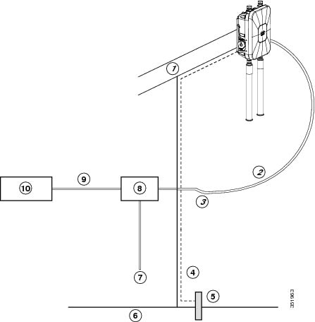
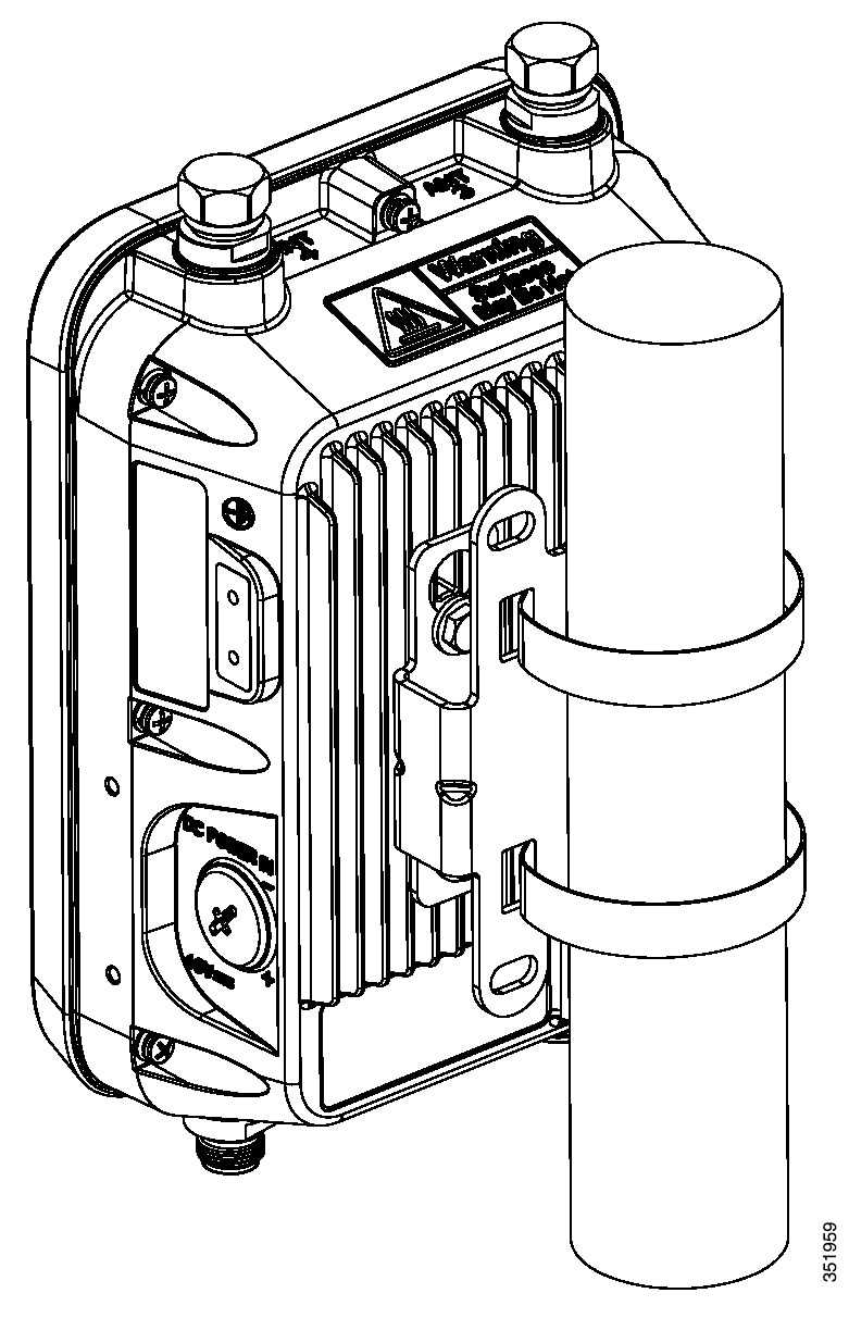
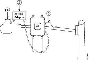
The access point is designed to be installed in an outdoor environment, such as the exterior roof overhang of a tall building or a streetlight pole. Carefully review the following figures to become familiar with the system components, connectors, indicators, cables, system interconnection, and grounding:
- Components in a typical access point installation (see Figure 2-1)
- Pole mount installation (see Figure 2-2)
- Streetlight power tap installation, works only with the AC/DC power adapter (see Figure 2-3). For information on how to connect to Streetlight AC power, see Connecting Streetlight AC Power.
Note that this type of deployment requires an alternate AP mounting kit. See Mounting the Access Point section for more information.
Note![]() The illustrations in this document show all available connections for the access point. Unused connections are capped with a connector plug to ensure the watertight integrity of the access point. Cable glands are provided for connector openings, which can be installed before or after deploying the access point.
The illustrations in this document show all available connections for the access point. Unused connections are capped with a connector plug to ensure the watertight integrity of the access point. Cable glands are provided for connector openings, which can be installed before or after deploying the access point.
Figure 2-1 Components in a Typical Access Point Installation
|
|
|
||
|
|
Shielded outdoor-rated Ethernet |
|
|
|
|
|
||
|
|
|
||
|
|
|
|
|
Warning![]() Installation of the equipment must comply with local and national electrical codes. Statement 1074
Installation of the equipment must comply with local and national electrical codes. Statement 1074
Figure 2-2 Standard Pole Mount Installation
|
|
|
||
|
|
|
||
|
|
Pole (wood, metal, or fiberglass) |
|
Figure 2-3 Streetlight Power Tap Adapter Installation
|
|
|
||
|
|
|
Mounting the Access Point
This section provides instructions for installing your access points. Personnel installing the access point must understand wireless access points and bridging techniques and grounding methods.
Installation Options
The 1530 Series Access Point can be wall, pole or tower mounted.There are two optional mounting kits: a fixed mounting kit (AIR-ACC1530-PMK1=) and a pivoting mounting kit (AIR-ACC1530-PMK2=).
Warning![]() Only trained and qualified personnel should be allowed to install, replace, or service this equipment. Statement 1030
Only trained and qualified personnel should be allowed to install, replace, or service this equipment. Statement 1030
Warning![]() Installation of the equipment must comply with local and national electrical codes. Statement 1074
Installation of the equipment must comply with local and national electrical codes. Statement 1074
Access Point Mounting Orientation
When mounting an access point on a horizontal or vertical surface, you must ensure that the access point is oriented with the LED indicators pointing down. This positioning allows LEDs to be visible to someone on the ground below the access point.
You must also ensure the access point is mounted in such a way as to ensure that all antenna ports and the console port are accessible for future use.
Note![]() Omnidirectional antennas are vertically polarized and should be mounted vertically.
Omnidirectional antennas are vertically polarized and should be mounted vertically.
Wall Mounting the Access Point with the Fixed Mounting Kit
The optional fixed mounting kit contains a mounting bracket for wall mounting or pole mounting. You can use the mounting bracket as a template to mark the positions of the mounting holes for your installation. You then install the mounting plate, and attach the access point when you are ready. Table 2-1 lists the materials you will need to provide in addition to the fixed mounting kit.
Table 2-1 Materials Required to Mount Access Point to a Vertical Wall
To mount the access point on a vertical wall, follow these instructions:
Step 1![]() Use the mounting bracket as a template to mark four screw hole locations on the mounting surface. See Figure 2-4 for the mounting bracket screw hole locations. Use the mounting slotted holes to attach the unit to the wall.
Use the mounting bracket as a template to mark four screw hole locations on the mounting surface. See Figure 2-4 for the mounting bracket screw hole locations. Use the mounting slotted holes to attach the unit to the wall.
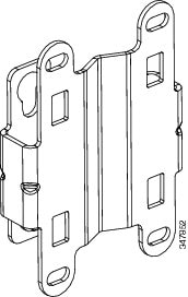
Figure 2-4 Mounting Bracket for Wall and Pole Mounting
|
|
|
||
|
|
Bracket Mount Holes (use bolts up to 1/4" or 6 mm in diameter) |
|
Step 2![]() Use four customer-supplied screws and optional screw-anchors to attach the mounting plate to the mounting surface.
Use four customer-supplied screws and optional screw-anchors to attach the mounting plate to the mounting surface.
Note![]() If necessary, use suitable screw anchors and an exterior-grade plywood backboard to mount the access point to stucco, cement or drywall.
If necessary, use suitable screw anchors and an exterior-grade plywood backboard to mount the access point to stucco, cement or drywall.
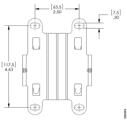
Figure 2-5 Mounting Bracket Dimensions
Step 3![]() Screw an M6 x12 mm bolt into each of the four support bolt holes on the back of the access point. Do not screw the bolt all the way in; leave approximately a 0.13 inch (3.3 mm) space.
Screw an M6 x12 mm bolt into each of the four support bolt holes on the back of the access point. Do not screw the bolt all the way in; leave approximately a 0.13 inch (3.3 mm) space.
Step 4![]() Position the four bolts on the access point into the keyhole slots on the mounting bracket.
Position the four bolts on the access point into the keyhole slots on the mounting bracket.
Step 5![]() Slide the access point down to sit securely in the quick mount notches.
Slide the access point down to sit securely in the quick mount notches.
Step 6![]() Using a 10mm wrench, secure the AP to the bracket by tightening the bolts to the bracket; torque to 40 lb-in.
Using a 10mm wrench, secure the AP to the bracket by tightening the bolts to the bracket; torque to 40 lb-in.
Step 7![]() Continue with the Grounding the Access Point.
Continue with the Grounding the Access Point.
Pole Mounting the Access Point with the Fixed Mount Kit
The optional fixed mounting kit contains a mounting bracket for wall mounting or pole mounting.This kit can be used to install the access point on a pole, mast or streetlight. It supports metal, wood or fiberglass poles from 2 to 8 inches in diameter.
Table 2-2 Materials Needed to Mount the AP on a Vertical Pole
To mount the access point onto a vertical pole or streetlight pole, follow these steps:
Step 1![]() Select a mounting location on the pole to mount the access point. You can attach the access point to any pole with a diameter from 2to 8 inches (5.1 to 20.1 cm).
Select a mounting location on the pole to mount the access point. You can attach the access point to any pole with a diameter from 2to 8 inches (5.1 to 20.1 cm).
Note![]() If you will be using a streetlight power tap adapter, position the access point within 3 ft (1 m) of the outdoor light control. The AC/DC adapter must be used with street light power tap.
If you will be using a streetlight power tap adapter, position the access point within 3 ft (1 m) of the outdoor light control. The AC/DC adapter must be used with street light power tap.
Step 2![]() Determine which size of band clamp is needed based on the pole diameter. Slide the two clamps through the top and bottom set of mounting slots (see Figure 2-4) and mount the bracket to the pole.
Determine which size of band clamp is needed based on the pole diameter. Slide the two clamps through the top and bottom set of mounting slots (see Figure 2-4) and mount the bracket to the pole.
Step 3![]() Wrap the band clamps around the pole and slide them into the second set of top and bottom mounting slots on the bracket. Lightly tighten the clamps. Only tighten them enough to keep the bracket from sliding down the pole.
Wrap the band clamps around the pole and slide them into the second set of top and bottom mounting slots on the bracket. Lightly tighten the clamps. Only tighten them enough to keep the bracket from sliding down the pole.
Step 4![]() Screw an M6 bolt into each of the four bolt holes on the back side of the access point. Do not screw the bolt in all the way. Leave a gap of about 0.13" (3.3mm).
Screw an M6 bolt into each of the four bolt holes on the back side of the access point. Do not screw the bolt in all the way. Leave a gap of about 0.13" (3.3mm).
Step 5![]() Position the four bolts on the access point into the bracket keyhole slots. Check to be sure that the access point is properly seated in the slots.(See Figure 2-6)
Position the four bolts on the access point into the bracket keyhole slots. Check to be sure that the access point is properly seated in the slots.(See Figure 2-6)
Note![]() The access point should be positioned with the LEDs on the bottom to allow viewing from the ground.
The access point should be positioned with the LEDs on the bottom to allow viewing from the ground.
Step 6![]() Using a 10mm wrench, tighten the four bolts that connect the access point to the bracket to a torque of 40 lbf-in.
Using a 10mm wrench, tighten the four bolts that connect the access point to the bracket to a torque of 40 lbf-in.
Step 7![]() Locate the access point to its final position. Tighten the band clamps with the wrench so that the access point does not slide on the pole. Ensure that the clamps are tight enough to not let the AP move.
Locate the access point to its final position. Tighten the band clamps with the wrench so that the access point does not slide on the pole. Ensure that the clamps are tight enough to not let the AP move.
Step 8![]() Continue with the Grounding the Access Point.
Continue with the Grounding the Access Point.
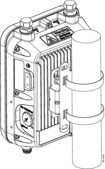
Figure 2-6 AP and Fixed Mount Kit Installed on a Pole
|
|
|
||
|
|
|
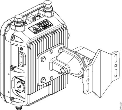
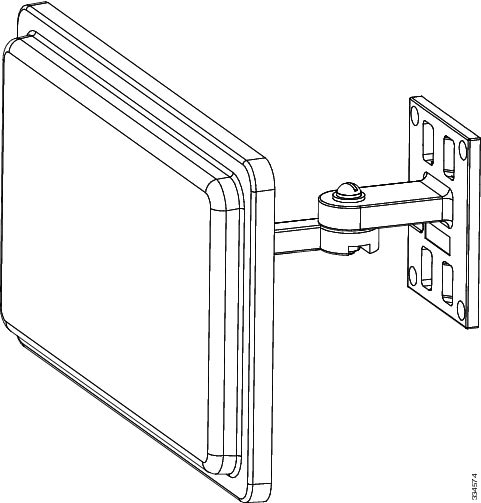
Wall Mounting the Access Point with the Pivoting Mounting Kit
The optional pivoting mounting kit contains a mounting bracket for wall or pole mounting. This kit can be used to install the access point on a wall while still allowing for some freedom of movement. This bracket supports metal, wood or fiberglass surfaces.
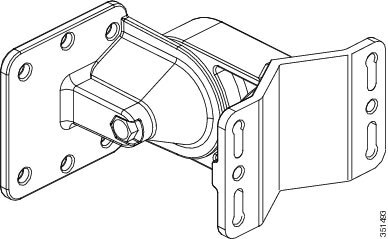
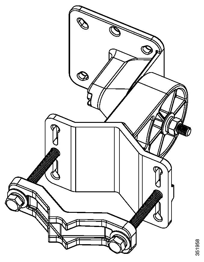
Figure 2-7 Pivoting Mounting Kit
|
|
|
||
|
|
|
Figure 2-8 Pivoting Mounting Kit Dimensions
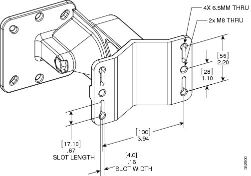
Table 2-3 Materials for Mounting on Wall with Pivoting Mounting Kit
Figure 2-9 AP wall mounted with Pivoting Mounting Kit
To mount the access point on a vertical wall, follow these instructions:
Step 1![]() Disassemble pivot kit, if not already done.
Disassemble pivot kit, if not already done.
Step 2![]() Use the mounting bracket as a template to mark four screw hole locations on the mounting surface. See Figure 2-7 for the mounting bracket screw hole locations (screw holes of maximum 6 mm in size).
Use the mounting bracket as a template to mark four screw hole locations on the mounting surface. See Figure 2-7 for the mounting bracket screw hole locations (screw holes of maximum 6 mm in size).
Step 3![]() Use four customer-supplied screws and optional screw-anchors to attach the mounting plate to the mounting surface.
Use four customer-supplied screws and optional screw-anchors to attach the mounting plate to the mounting surface.
Note![]() If necessary, use suitable screw anchors and an exterior-grade plywood backboard to mount the access point to stucco, cement or drywall.
If necessary, use suitable screw anchors and an exterior-grade plywood backboard to mount the access point to stucco, cement or drywall.
Step 4![]() Match the holes in the bracket plate to the holes in the back of the access point.
Match the holes in the bracket plate to the holes in the back of the access point.
Step 5![]() Screw an M8 x12 mm bolt into each of the four bolt holes (using a 10 mm box wrench or socket, torque the bolts to 40 lbf-in) on the back side of the access point and mounting bracket.
Screw an M8 x12 mm bolt into each of the four bolt holes (using a 10 mm box wrench or socket, torque the bolts to 40 lbf-in) on the back side of the access point and mounting bracket.
Step 6![]() Using the long bolt and the hardware supplied with the pivoting bracket, bolt the AP and its mounted bracket, on to the bracket mounted on the wall (see Figure 2-11 for an exploded view of this assembly).
Using the long bolt and the hardware supplied with the pivoting bracket, bolt the AP and its mounted bracket, on to the bracket mounted on the wall (see Figure 2-11 for an exploded view of this assembly).
Step 7![]() Pivot the AP to your desired position, and then tighten the bolts (using a 13 mm wrench).
Pivot the AP to your desired position, and then tighten the bolts (using a 13 mm wrench).
Step 8![]() Continue with Grounding the Access Point.
Continue with Grounding the Access Point.
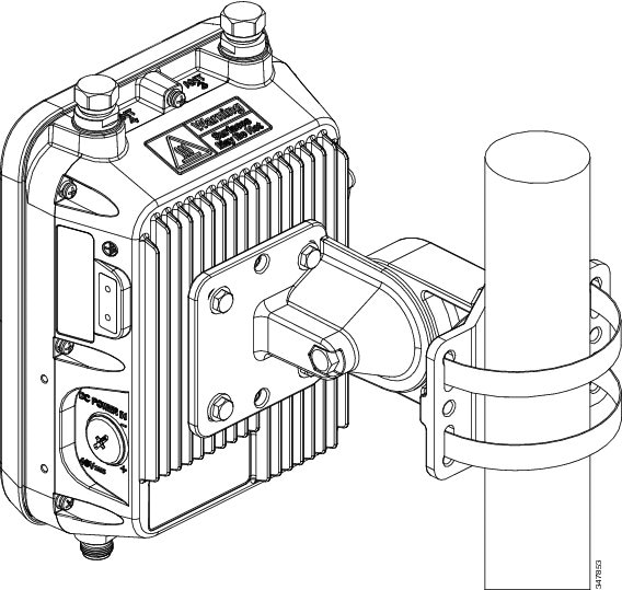
Pole Mounting the Access Point with the Pivoting Mounting Kit
The optional pivoting mounting kit contains a mounting bracket for wall mounting or pole mounting, along with a clamp for pole mounting.This kit can be used to install the access point on a pole, mast or streetlight. It supports metal, wood or fiberglass poles from 2 to 8 inches in diameter.
Figure 2-10 Pivoting Mounting Kit with Pole Mount Clamp
|
|
|
Slots for band clamps (band clamps are provided but not shown in this figure. See Figure 2-12). |
|
|
|
Pole mount clamp. It can fit poles of range up to 3 in. (76mm) |
|
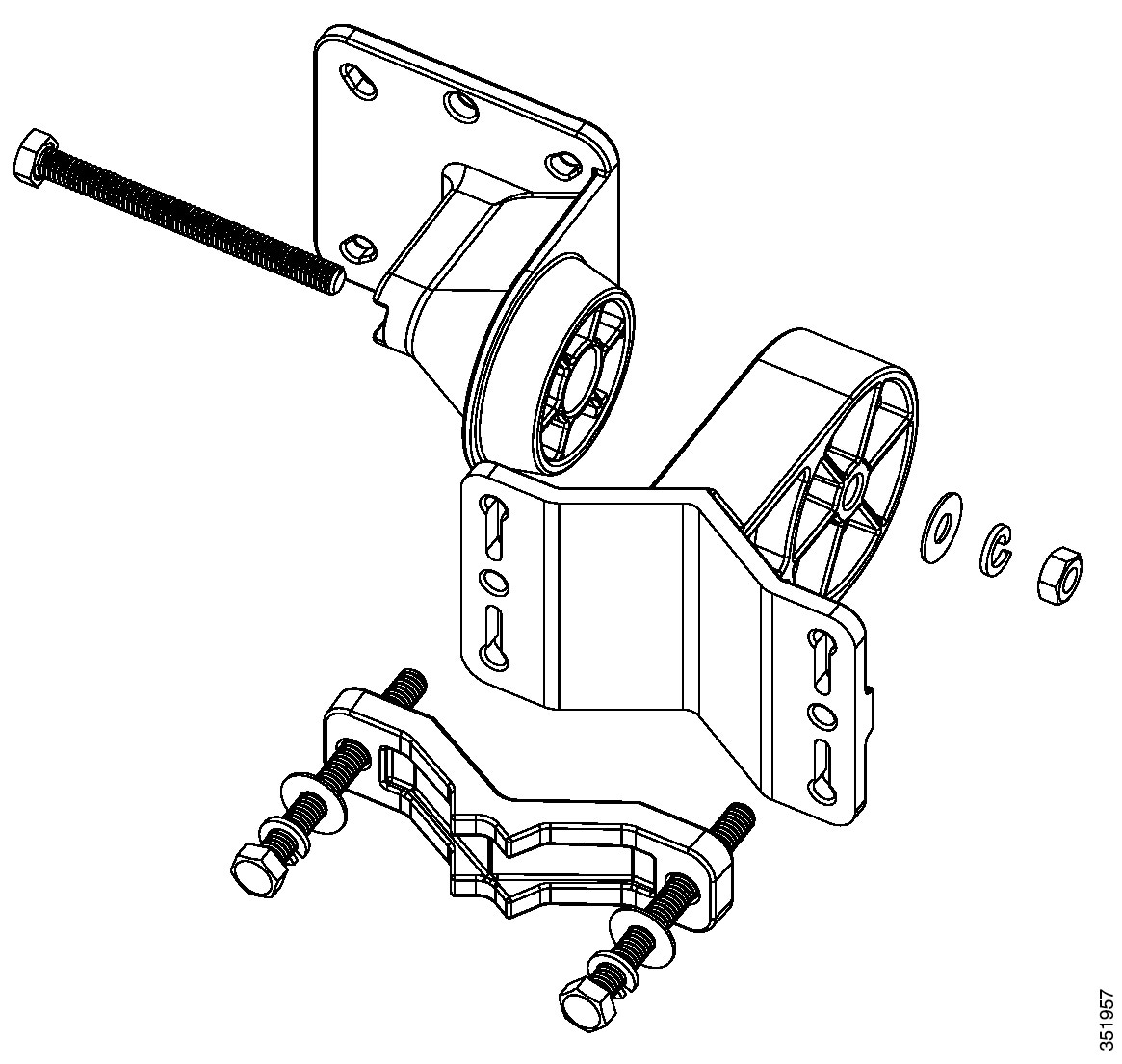
Figure 2-11 Exploded View of the Pivoting Mounting Kit
|
|
|
||
|
|
|
||
|
|
|
Table 2-4 Materials Needed to Mount the AP on a Vertical Pole with the Pivoting Mounting Kit
To mount the access point onto a vertical pole or streetlight pole, follow these steps:
Step 1![]() Select a mounting location on the pole to mount the access point. You can attach the access point to any pole with a diameter from 2 to 8 inches (5.1 to 40.6 cm).
Select a mounting location on the pole to mount the access point. You can attach the access point to any pole with a diameter from 2 to 8 inches (5.1 to 40.6 cm).
Note![]() If you will be using a streetlight power tap adapter, position the access point within 3 ft (1 m) of the outdoor light control.
If you will be using a streetlight power tap adapter, position the access point within 3 ft (1 m) of the outdoor light control.
Step 2![]() Mount the pivot bracket base to the pole using either one set of the adjustable band clamps or the screw clamp (the screw clamp can be used on a pole that is not more than 3 inches in diameter).
Mount the pivot bracket base to the pole using either one set of the adjustable band clamps or the screw clamp (the screw clamp can be used on a pole that is not more than 3 inches in diameter).
Step 3![]() Position the pole clamp bracket on the pole as needed before tightening the metal bands. Tighten the metal bands only enough to hold the bracket base in place, from sliding along the pole. Fully tighten the bands only after the access point is positioned.
Position the pole clamp bracket on the pole as needed before tightening the metal bands. Tighten the metal bands only enough to hold the bracket base in place, from sliding along the pole. Fully tighten the bands only after the access point is positioned.
Step 4![]() Match the holes in the bracket plate to the holes in the back of the access point.
Match the holes in the bracket plate to the holes in the back of the access point.
Step 5![]() Screw an M8 x12 mm bolt into each of the four bolt holes (using a 10 mm box wrench or socket, torque the bolts to 40 lbf-in) on the back side of the access point and mounting bracket. (See Figure 2-11)
Screw an M8 x12 mm bolt into each of the four bolt holes (using a 10 mm box wrench or socket, torque the bolts to 40 lbf-in) on the back side of the access point and mounting bracket. (See Figure 2-11)
Note![]() The access point should be positioned with the LEDs on the bottom to allow viewing from the ground.
The access point should be positioned with the LEDs on the bottom to allow viewing from the ground.
Step 6![]() Mount the bracket with the AP, to the bracket on the pole. Use the long screw for this, as shown in the exploded view – see Figure 2-11.
Mount the bracket with the AP, to the bracket on the pole. Use the long screw for this, as shown in the exploded view – see Figure 2-11.
Step 7![]() Point the AP in the general desired position and tighten bolt, and then tighten the clamps on the pole. The AP can be repositioned to its final position by loosening and re-tightening the bolts.
Point the AP in the general desired position and tighten bolt, and then tighten the clamps on the pole. The AP can be repositioned to its final position by loosening and re-tightening the bolts.
|
|
|
||
|
|
|
Metal Band Mounting Straps. |
Step 8![]() Continue with the Grounding the Access Point
Continue with the Grounding the Access Point
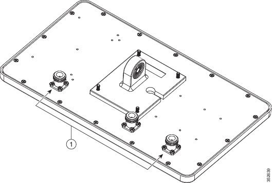
Horizontally Mounting the Access Point with Optional Horizontal Mount Plate
The pivoting pole mount kit also contains a plate that allows the option of the AP enclosure to be mounted horizontally (See Figure 2-13).
Table 2-5 Materials Needed to Mount the AP on a Vertical Pole with the Pivoting Mounting Kit
Step 1![]() Mount the pivot bracket to a wall or a pole as shown in the previous procedures.
Mount the pivot bracket to a wall or a pole as shown in the previous procedures.
Step 2![]() Using four M6 x 12 mm bolts mount the horizontal adapter plate to the bracket mount plate.
Using four M6 x 12 mm bolts mount the horizontal adapter plate to the bracket mount plate.
Do not mount the pivot bracket mounting plate directly to the access point.
Step 3![]() Using the remaining four M6 x 12 mm bolts, mount the other side of the horizontal mounting plate to the AP. See Figure 2-14 for the exploded view.
Using the remaining four M6 x 12 mm bolts, mount the other side of the horizontal mounting plate to the AP. See Figure 2-14 for the exploded view.
Step 4![]() Using a 10 mm wrench or socket, tighten all M6 bolts to 40 lbf-in (4.5 Nm).
Using a 10 mm wrench or socket, tighten all M6 bolts to 40 lbf-in (4.5 Nm).
Step 5![]() Position the access point as needed and tighten the mount kit bolts using a 13 mm wrench or socket.
Position the access point as needed and tighten the mount kit bolts using a 13 mm wrench or socket.
Figure 2-13 Access Point Horizontally Mounted using the Optional Horizontal Mount Plate
Figure 2-14 Exploded View of a Horizontally Mounted Access Point
|
|
|
||
|
|
Screw holes for mounting the horizontal mounting plate to the pivoting bracket |
|
Screw holes for mounting the horizontal mounting plate to the access point |
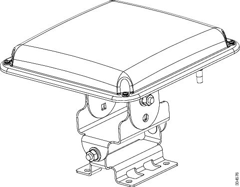
Installing AP Cover or Solar Shield (AIR-ACC1530-CVR=)
You can install an optional solar shield AIR-ACC1530-CVR= to cover the AP.
Note![]() The cover can be installed prior to or after all connections are made. The only exception is when remote cabled antennas are installed – in such cases, the shield must be installed before the antenna cables are attached to the AP.
The cover can be installed prior to or after all connections are made. The only exception is when remote cabled antennas are installed – in such cases, the shield must be installed before the antenna cables are attached to the AP.
Figure 2-15 Installing the Solar Shield
|
|
|
Step 1![]() Position and slide the cover over the AP as shown in Figure 2-15.
Position and slide the cover over the AP as shown in Figure 2-15.
Step 2![]() Align the two holes on each side of the cover with the screw holes on corresponding side of the AP.
Align the two holes on each side of the cover with the screw holes on corresponding side of the AP.
Step 3![]() Insert and install #8-32 screws through the screw holes in the cover and into the AP. Tighten the screws to 10 lb-in.
Insert and install #8-32 screws through the screw holes in the cover and into the AP. Tighten the screws to 10 lb-in.
Installing Antennas
Table 2-6 shows the antennas supported by the 1532 access point and provides required quantities for each model.
|
|
|
|
|
|---|---|---|---|
For installation instructions and detailed information on these antennas, refer to the appropriate document located at:
http://www.cisco.com/c/en/us/support/wireless/aironet-antennas-accessories/products-installation-guides-list.html
Follow all safety precautions when installing the antennas. For information on safety, refer to “Safety Precautions when Installing Antennas” section.
Non-Cisco Antennas
Cisco does not support any third-party antennas. RF connectivity and compliance of third party antennas is the customer’s responsibility. Cisco does not recommend any third-party antennas, and Cisco Technical Assistance Center will not be able to provide any support for third-party antennas. Cisco’s FCC Part 15 compliance is only guaranteed with Cisco antennas or antennas that are of the same design and gain as Cisco antennas.
Safety Precautions when Installing Antennas
Warning![]() Do not locate the antenna near overhead power lines or other electric light or power circuits, or where it can come into contact with such circuits. When installing the antenna, take extreme care not to come into contact with such circuits, as they may cause serious injury or death. For proper installation and grounding of the antenna, please refer to national and local codes (e.g. U.S.: NFPA 70, National Electrical Code, Article 810, Canada: Canadian Electrical Code, Section 54). Statement 280
Do not locate the antenna near overhead power lines or other electric light or power circuits, or where it can come into contact with such circuits. When installing the antenna, take extreme care not to come into contact with such circuits, as they may cause serious injury or death. For proper installation and grounding of the antenna, please refer to national and local codes (e.g. U.S.: NFPA 70, National Electrical Code, Article 810, Canada: Canadian Electrical Code, Section 54). Statement 280
1.![]() Before you install an antenna, contact your Cisco account representative to explain which mounting method to use for the size and type of antenna that you are about to install.
Before you install an antenna, contact your Cisco account representative to explain which mounting method to use for the size and type of antenna that you are about to install.
2.![]() Select your installation site with safety, as well as performance, in mind. Remember that electric power lines and phone lines look alike. For your safety, assume that any overhead line can kill you.
Select your installation site with safety, as well as performance, in mind. Remember that electric power lines and phone lines look alike. For your safety, assume that any overhead line can kill you.
3.![]() Contact your electric power company. Tell them your plans and ask them to come look at your proposed installation.
Contact your electric power company. Tell them your plans and ask them to come look at your proposed installation.
4.![]() Plan your installation carefully and completely before you begin. Each person involved in an installation should be assigned to a specific task and should know what to do and when to do it. One person should be in charge of the operation to issue instructions and watch for signs of trouble.
Plan your installation carefully and completely before you begin. Each person involved in an installation should be assigned to a specific task and should know what to do and when to do it. One person should be in charge of the operation to issue instructions and watch for signs of trouble.
5.![]() When installing your antenna, follow these guidelines:
When installing your antenna, follow these guidelines:
–![]() Do not work on a wet or windy day.
Do not work on a wet or windy day.
–![]() Do dress properly—wear shoes with rubber soles and heels, rubber gloves, and a long-sleeved shirt or jacket.
Do dress properly—wear shoes with rubber soles and heels, rubber gloves, and a long-sleeved shirt or jacket.
6.![]() If the assembly starts to drop, move away from it and let it fall. Because the antenna, mast, cable, and metal guy wires are all excellent conductors of electrical current, even the slightest touch of any of these parts to a power line completes an electrical path through the antenna and the installer.
If the assembly starts to drop, move away from it and let it fall. Because the antenna, mast, cable, and metal guy wires are all excellent conductors of electrical current, even the slightest touch of any of these parts to a power line completes an electrical path through the antenna and the installer.
7.![]() If any part of the antenna system should come in contact with a power line, do not touch it or try to remove it yourself. Call your local power company to have it removed safely.
If any part of the antenna system should come in contact with a power line, do not touch it or try to remove it yourself. Call your local power company to have it removed safely.
8.![]() If an accident should occur with the power lines, call for qualified emergency help immediately.
If an accident should occur with the power lines, call for qualified emergency help immediately.
Antenna Configurations
Integrated Antenna Option
The AP1532I uses an Integrated Low Profile Dual-Band 2.4-5 GHz Dipole Antenna Array. The antenna contains an array of three dual-band dipole antennas. The three dipole antennas are contained within this single radome, thereby greatly reducing the antenna’s visual footprint, and greatly reducing the possibility of snagging the antenna on the cable bundle, the RF cable, or test cables. Each of thee three dipole antennas is a dual-band antenna, covering both the 2.4 - 2.483 GHz band and the 5.25-5.85 GHz bands. The antenna have a peak gain of about 3 dBi at 2.4 GHz and 5 dBi at 5 GHz. The antenna unit is gray weatherproof radome for outdoor operations.
External Antenna Mounting Configurations
The selection of the antenna is determined in the configuration of the product. The 1532E antennas can be mounted on a wall, pole and/or tower mounted. Please refer to the Ordering Guide for a list of supported antennas.
The 1532E access point supports a variety of antennas designed for outdoor use with radios operating in the 2.4-GHz and 5-GHz frequency bands. The 1532 supports the external antennas listed in the following sections.
Cisco Aironet Dual-Band Omnidirectional Antenna (AIR-ANT2547V-N, AIR-ANT2547VG-N)
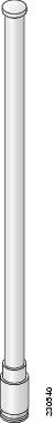
The Dual-Band Omnidirectional Antenna, referred to as a “stick” antenna, is designed for outdoor use with Cisco Aironet Outdoor Access Points with radios operating in the 2.4-GHz and 5-GHz frequency bands (Figure 2-16). Basic operating features of the antenna are:
The antenna is designed to create an omnidirectional broadcast pattern. To achieve this pattern, mount the access point clear of any obstructions to the sides of the radiating element.
For detailed information on this antenna, refer to the Cisco Aironet Dual-Band Omnidirectional Antenna (AIR-ANT2547V-N, AIR-ANT2547VG-N) document. Follow all safety precautions when installing the antennas. For information on safety, refer to “Safety Precautions when Installing Antennas” section.
Figure 2-16 Cisco Aironet Dual-Band Omnidirectional Antenna - Installed Only on Model AIR-CAP1532E-x-K9
|
|
Antenna connected to antenna port 1(Type-N connector) (TX/RX) |
|
Antenna connected to antenna port 2(Type-N connector) (TX/RX) |
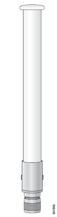
Cisco Aironet 2.4-GHz/5-GHz 8-dBi Directional Antenna (AIR-ANT2588P3M-N)
The Cisco Aironet 2.4-GHz/5-GHz 8-dBi Directional Antenna is designed for outdoor use with Cisco Aironet Outdoor Access Points with radios operating in both the 2.4-GHz and 5-GHz frequency bands. This antenna has 8-dBi gain in both bands.
For detailed information on this antenna, refer to the Cisco Aironet 2.4-GHz/5-GHz 8-dBi Directional Antenna (AIR-ANT2588P3M-N) document. Follow all safety precautions when installing the antennas, for information on safety, refer to “Safety Precautions when Installing Antennas” section.
Figure 2-17 Cisco Aironet 2.4-GHz/5-GHz 8-dBi Directional Antenna - Installed Only on Model AIR-CAP1532E-x-K9
Note![]() When installing the AIR-ANT2588P3M-N with the Cisco Aironet 1530 Series AP, connect the outermost antenna ports (marked ‘1’ in Figure 2-18) to the AP’s dual band antenna ports.
When installing the AIR-ANT2588P3M-N with the Cisco Aironet 1530 Series AP, connect the outermost antenna ports (marked ‘1’ in Figure 2-18) to the AP’s dual band antenna ports.
Figure 2-18 Antenna Ports For Connection to AP’s Dual Band Ports
Cisco Aironet 5-GHz 14-dBi 2-Port Directional Antenna (AIR-ANT5114P2M-N)
The Cisco Aironet 5-GHz 14-dBi 2-Port Directional Antenna is designed for outdoor use with Cisco Aironet Outdoor Access Points with radios operating in the 5-GHz frequency band. This antenna has 14-dBi in the 5-GHz band.
For more information, see the Cisco Aironet 5-GHz 14-dBi Directional Antenna document, at the following URL:
http://www.cisco.com/c/en/us/td/docs/wireless/antenna/installation/guide/ant5114p2m-n.html.
For detailed information on this antenna, see the Cisco Aironet 5-GHz 14-dBi Directional Antenna (AIR-ANT5114P2M-N) document. Follow all safety precautions when installing the antennas, for information on safety, refer to “Safety Precautions when Installing Antennas” section.
Figure 2-19 Cisco Aironet 5-GHz 14-dBi Directional Antenna - Installed Only on Models AIR-CAP1532E-x-K9
Cisco Aironet 2.4-GHz 13-dBi 2-Port Directional Antenna (AIR-ANT2413P2M-N)
The Cisco Aironet 2.4-GHz 13-dBi 2-Port Directional Antenna is designed for outdoor use with Cisco Aironet Outdoor Access Points with radios operating in the 2.4-GHz frequency band. This antenna has 13-dBi gain in the 2.4-GHz frequency band.
For detailed information on this antenna, refer to the Cisco Aironet 2.4-GHz 13-dBi Directional Antenna (AIR-ANT2413P2M-N) document. Follow all safety precautions when installing the antennas, for information on safety, refer to “Safety Precautions when Installing Antennas” section.
Figure 2-20 Cisco Aironet 2.4-GHz 13-dBi Directional Antenna - Installed Only on Models AIR-CAP1532E-x-K9
Cisco Aironet 2.4-GHz 5-dBi Omnidirectional Antenna (AIR-ANT2450V-N)
The Cisco Aironet 2.4-GHz 5-dBi Omnidirectional Antenna is designed for outdoor use with Cisco Aironet Outdoor Access Points with radios operating in the 2.4-GHz frequency band. This antenna has a 5-dBi gain in the 2.4-GHz band.
For detailed information on this antenna, refer to the document Cisco Aironet 5-dBI Omnidirectional Antenna (AIR-ANT2450V-N). Follow all safety precautions when installing the antennas. For information on safety, refer to “Safety Precautions when Installing Antennas” section.
Figure 2-21 Cisco Aironet 2.4-GHz 5-dBi Omni Antenna - Installed Only on Model AIR-CAP1532E-x-K9
Cisco Aironet 2.4-GHz 8-dBi Omnidirectional Antenna (AIR-ANT2480V-N)
The Cisco Aironet 2.4-GHz 8-dBi Omnidirectional Antenna is designed for outdoor use with Cisco Aironet Outdoor Access Points with radios operating in the 2.4-GHz frequency band. This antenna has 8-dBi gain in the 2.4-GHz frequency band.
For detailed information on this antenna, refer to the document Cisco Aironet 8-dBi Omnidirectional Antenna (AIR-ANT2480V-N). Follow all safety precautions when installing the antennas, for information on safety, refer to “Safety Precautions when Installing Antennas” section.
Figure 2-22 Cisco Aironet 2.4-GHz 8-dBi Omni Antenna - Installed Only on Model AIR-CAP1532E-x-K9i
Cisco Aironet 5-GHz 8-dBi Omnidirectional Antenna (AIR-ANT5180V-N)
The Cisco Aironet 5-GHz 8-dBi Omnidirectional Antenna is designed for outdoor use with Cisco Aironet Outdoor Access Points with radios operating in the 5-GHz frequency band. This antenna has 8-dBi gain in the 5-GHz frequency band.
For detailed information on this antenna, refer to the document Cisco Aironet 8-dBi Omnidirectional Antenna (AIR-ANT5180V-N). Follow all safety precautions when installing the antennas, for information on safety, refer to “Safety Precautions when Installing Antennas” section.
Figure 2-23 Cisco Aironet 5-GHz 8-dBi Omnidirectional Antenna - Installed Only on Model AIR-CAP1532E-x-K9
Antenna N-Type Connector Locations
The access point antenna N-type connectors are located on the top and the bottom of model AIR-CAP1532E-x-K9. The N-type connectors support variety of the Cisco Aironet antennas. For detailed information on these antennas, refer to Antenna Configurations. Figure 2-24 shows the antenna port locations viewed from the RF cover side.
Figure 2-24 Antenna Port Locations - Model AIR-CAP1532E-x-K9
|
|
|
||
|
|
|
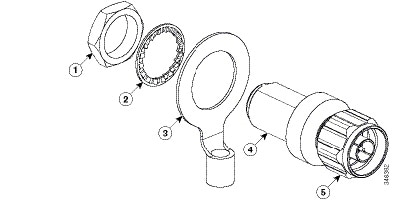
Installing a Lightning Arrestor
Overvoltage transients can be created through lightning static discharges, switch processes, direct contact with power lines, or through earth currents. The Cisco Aironet AIR-ACC245LA-N Lightning Arrestor limits the amplitude and duration of disturbing interference voltages and improves the over voltage resistance of in-line equipment, systems, and components. A lightning arrestor installed according to these mounting instructions balances the voltage potential, thus preventing inductive interference to parallel signal lines within the protected system.
Installation Considerations
Cisco recommends that you bulkhead mount the lightning arrestor so it can be installed as a wall-feed through on the wall of the protected space.
The importance of obtaining a good ground and bonding connection cannot be overstressed. Consider these points when grounding the lightning arrestor:
Installation Notes
This lightning arrestor is designed to be installed between the antenna cable that is attached to an outdoor antenna and the Cisco Aironet wireless device. You can install the lightning arrestor either indoors or outdoors. It can be connected directly to a wireless device having an external N connector. It can also be mounted inline or as a feed-through. Feed-through installations require 5/8 in. (16 mm) hole to accommodate the lightning arrestor.
Note![]() This lightning arrestor is part of a lightning arrestor kit. The kit contains a lightning arrestor and a grounding lug.
This lightning arrestor is part of a lightning arrestor kit. The kit contains a lightning arrestor and a grounding lug.
Note![]() When you install the lightning arrestor, follow the regulations or best practices applicable to lightning protection installation in your local area.
When you install the lightning arrestor, follow the regulations or best practices applicable to lightning protection installation in your local area.
Installing the Lightning Arrestor Outdoors
If you install the lightning arrestor outdoors, use the supplied ground lug and a heavy wire (#6 solid copper) to connect it to a good earth ground, such as a ground rod. The connection should be as short as possible.
Figure 2-25 Lightning Arrestor Details
|
|
|
||
|
|
|
||
|
|
|||
Cable for the Lightning Arrestor
Coaxial cable loses efficiency as the frequency increases, resulting in signal loss. The cable should be kept as short as possible because cable length also determines the amount of signal loss (the longer the run, the greater the loss).
Cisco recommends a high-quality, low-loss cable for use with the lightning arrestor.
Grounding the Access Point
The access point must be grounded before connecting power.
Warning![]() This equipment must be externally grounded using a customer-supplied ground wire before power is applied. Contact the appropriate electrical inspection authority or an electrician if you are uncertain that suitable grounding is available. Statement 366
This equipment must be externally grounded using a customer-supplied ground wire before power is applied. Contact the appropriate electrical inspection authority or an electrician if you are uncertain that suitable grounding is available. Statement 366
Warning![]() Installation of the equipment must comply with local and national electrical codes. Statement 1074
Installation of the equipment must comply with local and national electrical codes. Statement 1074
In all outdoor installations and when powering the access point with AC power, you must follow these instructions to properly ground the case:
Step 1![]() If using insulated 6-AWG copper ground wire, strip the insulation as required for the grounding lug.
If using insulated 6-AWG copper ground wire, strip the insulation as required for the grounding lug.
Step 2![]() Use the appropriate crimping tool to crimp the bare 6-AWG copper ground wire to the supplied grounding lug.
Use the appropriate crimping tool to crimp the bare 6-AWG copper ground wire to the supplied grounding lug.
Note![]() The grounding lug and hardware used must comply with local and national electrical codes.
The grounding lug and hardware used must comply with local and national electrical codes.
Step 3![]() Open the anti-corrosion sealant (supplied), and apply a liberal amount over the metal surface where the ground strap screw holes are located (see Figure 1-5).
Open the anti-corrosion sealant (supplied), and apply a liberal amount over the metal surface where the ground strap screw holes are located (see Figure 1-5).
Step 4![]() Connect the grounding lug to the access point grounding screw holes (see Figure 1-5) using the supplied two Phillips head screws (M4 x10 mm) with lock washers. Tighten the grounding screw to 22 to 24 lb-in (2.49 to 2.71 Nm).
Connect the grounding lug to the access point grounding screw holes (see Figure 1-5) using the supplied two Phillips head screws (M4 x10 mm) with lock washers. Tighten the grounding screw to 22 to 24 lb-in (2.49 to 2.71 Nm).
Step 5![]() If necessary, strip the other end of the ground wire and connect it to a reliable earth ground, such as a grounding rod or an appropriate grounding point on a metal streetlight pole that is grounded (see Figure 2-3).
If necessary, strip the other end of the ground wire and connect it to a reliable earth ground, such as a grounding rod or an appropriate grounding point on a metal streetlight pole that is grounded (see Figure 2-3).
Powering the Access Point
Warning![]() Installation of the equipment must comply with local and national electrical codes. Statement 1074
Installation of the equipment must comply with local and national electrical codes. Statement 1074
Warning![]() This equipment must be externally grounded using a customer-supplied ground wire before power is applied. Contact the appropriate electrical inspection authority or an electrician if you are uncertain that suitable grounding is available. Statement 366
This equipment must be externally grounded using a customer-supplied ground wire before power is applied. Contact the appropriate electrical inspection authority or an electrician if you are uncertain that suitable grounding is available. Statement 366
Warning![]() Do not work on the system or connect or disconnect cables during periods of lightning activity. Statement 1001
Do not work on the system or connect or disconnect cables during periods of lightning activity. Statement 1001
The 1532 access point supports these power sources:
The 1532 access point can be powered via the PoE input from an in-line power injector or a suitably powered switch port. Depending on the configuration and regulatory domain, the required power for full operation is UPoE. For the 1532E, 802.3at power is sufficient for all regulatory domains and full 2x2 MIMO operation on both 2.4 and 5 GHz radios. Either the AIR-PWRINJ-30= or the AIR-PWRINJ1500-2= power injector can be used.
For the 1532I, UPoE powered switch port or the AIR-PWRINJ1500-2= power injector is required for full operation of the 3x3 MIMO on the 2.4 GHz radio in the regulatory domains that allow for high 2.4 GHz transmit power (Regulatory domains -A, -D, -F, -K, -N, -Q, -T, -Z). If the 1532I is powered by a PoE+ (802.3at power) switch port or the AIR-PWRINJ-30= power injector, then the access point will automatically disable one of the 2.4 GHz transmitters and the radio will operate in 2x3 MIMO mode.
Table 2-7 AP 1530 Power Matrix
|
|
|
|
|
|
|
|
|---|---|---|---|---|---|---|
One Tx disabled2 |
||||||
|
2.Not user configurable. AP will automatically disable one of the 2.4 GHz Tx if it detects only 802.3at power input. |
Warning![]() Connect the unit only to DC power source that complies with the Safety Extra-Low Voltage (SELV) requirements in IEC 60950 based safety standards Statement 1033
Connect the unit only to DC power source that complies with the Safety Extra-Low Voltage (SELV) requirements in IEC 60950 based safety standards Statement 1033
Connecting a 1530 Series Power Injector
The 1530 Series Access Points support the following power injectors:
- AIR-PWRINJ1500-2= — 100-240 VAC input, indoor use only
- AIR-PWRINJ-30= — 100-240 VAC input, indoor use only
The power injector provides (AIR-PWRINJ1500-2=) 56 VDC to the access point over the Ethernet cable and supports a total end-to-end Ethernet cable length of 100 m (328 ft) from the switch to the access point.
When your access point is powered by an optional power injector, follow these steps to complete the installation:
Step 1![]() Before applying PoE to the access point, ensure that the access point is grounded (see the “Grounding the Access Point” section).
Before applying PoE to the access point, ensure that the access point is grounded (see the “Grounding the Access Point” section).
Step 2![]() Review Figure 2-2 to identify the components needed for the installation.
Review Figure 2-2 to identify the components needed for the installation.
Note![]() The 1500 power injector can only be used in an indoor environment, therefore, the cable from the injector must travel from the protected location to the outside mounted access point.
The 1500 power injector can only be used in an indoor environment, therefore, the cable from the injector must travel from the protected location to the outside mounted access point.
Step 3![]() Connect a CAT5e or better Ethernet cable from your wired LAN network to the power injector.
Connect a CAT5e or better Ethernet cable from your wired LAN network to the power injector.
Warning![]() To reduce the risk of fire, use only No. 26 AWG or larger telecommunication line cord. Statement 1023
To reduce the risk of fire, use only No. 26 AWG or larger telecommunication line cord. Statement 1023
Note![]() The installer is responsible for ensuring that powering the access point from this type of power injector is allowed by local and/or national safety and telecommunications equipment standards.
The installer is responsible for ensuring that powering the access point from this type of power injector is allowed by local and/or national safety and telecommunications equipment standards.

Tip To forward bridge traffic, add a switch between the power injector and controller. Refer to the Cisco Wireless Mesh Access Points, Design and Deployment Guide, Release 7.0 for more information.
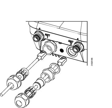
Step 4![]() Ensure that the antennas are connected and that a ground is attached to the access point before you apply power to the access point.
Ensure that the antennas are connected and that a ground is attached to the access point before you apply power to the access point.
Step 5![]() Connect a shielded outdoor-rated Ethernet (CAT5e or better) cable between the power injector and the PoE-in connector of the access point (see Figure 2-26).
Connect a shielded outdoor-rated Ethernet (CAT5e or better) cable between the power injector and the PoE-in connector of the access point (see Figure 2-26).
Step 6![]() Connect the Ethernet cable to the access point PoE-In port (see “Connecting an Ethernet Cable to the Access Point” section).
Connect the Ethernet cable to the access point PoE-In port (see “Connecting an Ethernet Cable to the Access Point” section).
Step 7![]() Continue with What to Do Next.
Continue with What to Do Next.
Connecting an Ethernet Cable to the Access Point
You need to supply these tools and materials:
- Shielded outdoor-rated Ethernet (CAT5e or better) cable with 0.2 to 0.35 in. (0.51 to 0.89 cm) diameter
- RJ-45 connector and installation tool
- Adjustable Wrench or 28 mm box wrench
- Large Phillips or Flat Blade screwdriver
To connect the shielded Ethernet cable to the access point, follow these steps:
Step 1![]() Disconnect power to the power injector, and ensure all power sources to the access point are turned off.
Disconnect power to the power injector, and ensure all power sources to the access point are turned off.
Warning![]() This unit might have more than one power supply connection. All connections must be removed to de-energize the unit. Statement 1028
This unit might have more than one power supply connection. All connections must be removed to de-energize the unit. Statement 1028
Step 2![]() Ensure a 6 AWG ground wire is connected to the access point (see the “Grounding the Access Point” section).
Ensure a 6 AWG ground wire is connected to the access point (see the “Grounding the Access Point” section).
Step 3![]() Use a large Phillips or Flat Blade screw driver to remove the Ethernet connector plug from the access point. Do not discard plug and rubber seal unless you are certain that the port will not have to be re-plugged (see Figure 2-26 for the location).
Use a large Phillips or Flat Blade screw driver to remove the Ethernet connector plug from the access point. Do not discard plug and rubber seal unless you are certain that the port will not have to be re-plugged (see Figure 2-26 for the location).
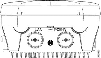
Figure 2-26 Access Point PoE-In Connector- AP 1532I
|
|
|
Note![]() For information on data cable entry, refer to Figure 1-1
For information on data cable entry, refer to Figure 1-1
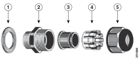
Step 4![]() Loosen the Thread-Lock sealing nut of the cable gland by turning it counter clockwise, but do not remove it (see Figure 2-27).
Loosen the Thread-Lock sealing nut of the cable gland by turning it counter clockwise, but do not remove it (see Figure 2-27).
Note![]() Verify that the cable gland has a rubber seal and ensure that it is not damaged.
Verify that the cable gland has a rubber seal and ensure that it is not damaged.
Warning![]() Failure to install the cable gland and rubber gasket properly will cause the cable grip to leak.
Failure to install the cable gland and rubber gasket properly will cause the cable grip to leak.
|
|
|
||
|
|
|
||
|
|
|
Step 5![]() Insert the unterminated end of the Ethernet cable through the sealing nut end of the cable gland (see Figure 2-27), and pull several inches of cable through the adapter.
Insert the unterminated end of the Ethernet cable through the sealing nut end of the cable gland (see Figure 2-27), and pull several inches of cable through the adapter.
Step 6![]() Install an RJ-45 connector on the unterminated end of the Ethernet cable using your Ethernet cable installation tool.
Install an RJ-45 connector on the unterminated end of the Ethernet cable using your Ethernet cable installation tool.
Warning![]() To reduce the risk of fire, use only No. 26 AWG or larger telecommunication line cord. Statement 1023
To reduce the risk of fire, use only No. 26 AWG or larger telecommunication line cord. Statement 1023
Warning![]() When installing the RJ-45 connector, ensure that cable gland and the rubber gasket are present and installed properly, to avoid water leakage into the enclosure. See Figure 2-27 and Figure 2-28.
When installing the RJ-45 connector, ensure that cable gland and the rubber gasket are present and installed properly, to avoid water leakage into the enclosure. See Figure 2-27 and Figure 2-28.
Step 7![]() Carefully insert the RJ-45 cable connector into the Ethernet port opening on the access point, and connect to the internal Ethernet connector (see Figure 2-28).
Carefully insert the RJ-45 cable connector into the Ethernet port opening on the access point, and connect to the internal Ethernet connector (see Figure 2-28).
Figure 2-28 Inserting RJ-45 Connector into the Ethernet Port Opening in Case
|
|
|
RJ-45 connector, on shielded outdoor-rated Ethernet (CAT5e or better) cable |
|
|
|
|||
Step 8![]() Slide the cable gland with the rubber seal towards the access point, and screw the threaded end of the body into the access point, and hand-tighten.
Slide the cable gland with the rubber seal towards the access point, and screw the threaded end of the body into the access point, and hand-tighten.
Step 9![]() Use an adjustable wrench or a 28-mm wrench to tighten the threaded end of the body into the enclosure. Tighten to 15 lb-in.
Use an adjustable wrench or a 28-mm wrench to tighten the threaded end of the body into the enclosure. Tighten to 15 lb-in.
Step 10![]() Use an adjustable wrench and tighten the thread-lock seal nut to 15 lb-in.
Use an adjustable wrench and tighten the thread-lock seal nut to 15 lb-in.
Step 11![]() Ensure that the antennas are connected to the access point before you apply power to the access point.
Ensure that the antennas are connected to the access point before you apply power to the access point.
Step 12![]() Route your Ethernet cable, and cut off any excess cable.
Route your Ethernet cable, and cut off any excess cable.
Step 13![]() Install an RJ-45 connector on the unterminated cable end, and insert it into the power injector. For typical installation components, see Figure 2-2.
Install an RJ-45 connector on the unterminated cable end, and insert it into the power injector. For typical installation components, see Figure 2-2.
Step 14![]() Turn on power to the power injector.
Turn on power to the power injector.
Connecting a DC Power Cable to the Access Point
When powering the access point with DC power, you must ensure that DC power can be conveniently removed from the unit. The power should not be removed by disconnecting the DC power connector on the unit.
Warning![]() A readily accessible two-poled disconnect device must be incorporated in the fixed wiring.
A readily accessible two-poled disconnect device must be incorporated in the fixed wiring.
Statement 1022
Warning![]() Connect the unit only to DC power source that complies with the safety extra-low voltage (SELV) requirements in IEC 60950 based safety standards. Statement 1033
Connect the unit only to DC power source that complies with the safety extra-low voltage (SELV) requirements in IEC 60950 based safety standards. Statement 1033
To connect a DC power cable, you need to supply these tools and material:
- Shielded outdoor-rated DC power cable (minimum 18 AWG) with outside cable diameter of 0.20 to 0.35 inch (0.51 to 0.89 cm).
- Adjustable or open-end wrench
- Small flat screw driver
- Two-pin DC power connector (Cisco supplied)
To connect the DC power cable to the access point, follow these steps:
Step 1![]() Before connecting DC power to the access point, ensure that the ground is connected to the access point (see the “Grounding the Access Point” section).
Before connecting DC power to the access point, ensure that the ground is connected to the access point (see the “Grounding the Access Point” section).
Step 2![]() Turn off all power sources to the access point, including the DC power source.
Turn off all power sources to the access point, including the DC power source.
Warning![]() This unit might have more than one power supply connection. All connections must be removed to de-energize the unit. Statement 1028
This unit might have more than one power supply connection. All connections must be removed to de-energize the unit. Statement 1028
Step 3![]() Use a large Phillips or Flat Blade screw driver to remove the Ethernet connector plug from the access point. Do not discard plug and rubber seal unless you are certain that the port will not have to be re-plugged. (see Figure 2-29 for the location of the DC power connector).
Use a large Phillips or Flat Blade screw driver to remove the Ethernet connector plug from the access point. Do not discard plug and rubber seal unless you are certain that the port will not have to be re-plugged. (see Figure 2-29 for the location of the DC power connector).
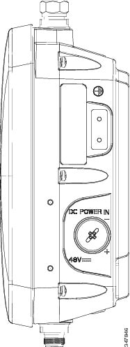
Figure 2-29 Access Point DC Power Connector and Ground Lug (Both AP 1532 Models)
|
|
|
Step 4![]() Loosen the thread-Lock sealing nut of the cable gland by turning it counter clockwise, but do not remove (see Figure 2-30).
Loosen the thread-Lock sealing nut of the cable gland by turning it counter clockwise, but do not remove (see Figure 2-30).
Note![]() Verify that the cable gland has a rubber seal and ensure that it is not damaged.
Verify that the cable gland has a rubber seal and ensure that it is not damaged.
Warning![]() Failure to install the Cable Gland properly will cause the cable grip to leak.
Failure to install the Cable Gland properly will cause the cable grip to leak.
|
|
|
||
|
|
|
||
|
|
|
Note![]() The cable gland accepts a cable diameter of 0.20 to 0.35 in. (0.51 to 0.89 cm).
The cable gland accepts a cable diameter of 0.20 to 0.35 in. (0.51 to 0.89 cm).
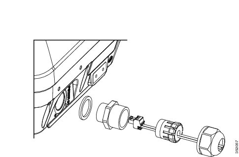
Step 5![]() Insert a bare end of the DC power cable into the rounded end of the cable gland (see Figure 2-30), and pull approximately 6 inches of cable through the adapter.
Insert a bare end of the DC power cable into the rounded end of the cable gland (see Figure 2-30), and pull approximately 6 inches of cable through the adapter.
Warning![]() When installing the DC power cable, ensure that cable gland and the rubber gasket are present and installed properly, to avoid water leakage into the enclosure. See Figure 2-30 and Figure 2-32.
When installing the DC power cable, ensure that cable gland and the rubber gasket are present and installed properly, to avoid water leakage into the enclosure. See Figure 2-30 and Figure 2-32.
Step 6![]() Strip the DC cable jacket back about 1 inch to expose the wires and strip the insulation about 3/8 inch (9.5 mm) from each wire.
Strip the DC cable jacket back about 1 inch to expose the wires and strip the insulation about 3/8 inch (9.5 mm) from each wire.
Step 7![]() Insert each wire into the two-position terminal strip (supplied), and tighten each wire using a 0.1 inch
Insert each wire into the two-position terminal strip (supplied), and tighten each wire using a 0.1 inch
(0.25 cm) flat screw driver (see Figure 2-31).
Figure 2-31 Two-Position Terminal Strip
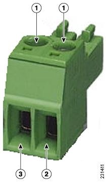
|
|
|
||
|
|
|
Step 8![]() Insert the two-position terminal strip into the DC power opening in the access point case, and carefully push the terminal strip into the internal connector (see Figure 2-32).
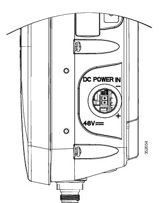
Insert the two-position terminal strip into the DC power opening in the access point case, and carefully push the terminal strip into the internal connector (see Figure 2-32).
Note![]() Ensure that the polarity of the terminal strip properly matches the polarity markings on the enclosure (see Figure 2-33)
Ensure that the polarity of the terminal strip properly matches the polarity markings on the enclosure (see Figure 2-33)
Figure 2-32 Inserting the Terminal Strip into the DC Power Opening in the Access Point Case
|
|
DC power opening in access point case. Also see Figure 2-33. |
|
Figure 2-33 DC Power Opening in the Access Point Case
Step 9![]() Slide the cable gland with the rubber seal towards the access point, and screw the threaded end of the body into the access point, and hand-tighten.
Slide the cable gland with the rubber seal towards the access point, and screw the threaded end of the body into the access point, and hand-tighten.
Step 10![]() Use an adjustable wrench, a 28-mm wrench to tighten the threaded end of the body to 15 lb-in.
Use an adjustable wrench, a 28-mm wrench to tighten the threaded end of the body to 15 lb-in.
Step 11![]() Use an adjustable wrench and tighten the thread-lock seal nut to 15 lb-in.
Use an adjustable wrench and tighten the thread-lock seal nut to 15 lb-in.
Step 12![]() Ensure that the antennas are connected to the access point before you apply power to the access point.
Ensure that the antennas are connected to the access point before you apply power to the access point.
Connecting Streetlight AC Power
The access point can be installed on a streetlight pole and powered from a streetlight outdoor light control using the optional streetlight power tap adapter (AIR-PWR-ST-LT-R3P) and AC/DC power adapter, AIR-PWRADPT-1530=. The AC/DC power adapter is used inline from the street light tap to the 1530 DC connector. The AC power tap only can be used with the AC/DC power adapter
100-to 277-VAC 50/60 Hz power. Do not connect to an outdoor light control powered by higher voltages.
When powering the access point with AC power other than the streetlight power tap adapter, you must ensure that the following conditions are observed:
1.![]() AC power can be conveniently removed from the unit. The power should not be removed by disconnecting the AC power connector on the unit.
AC power can be conveniently removed from the unit. The power should not be removed by disconnecting the AC power connector on the unit.
Warning![]() A readily accessible two-poled disconnect device must be incorporated in the fixed wiring.
A readily accessible two-poled disconnect device must be incorporated in the fixed wiring.
Statement 1022
2.![]() You must protect any AC power plugs and AC receptacles from water and other outdoor elements. You can use a UL-listed waterproofing enclosure suitable for covering the AC receptacle and AC power plug that supplies power to the unit as described in Article 406 of the NEC.
You must protect any AC power plugs and AC receptacles from water and other outdoor elements. You can use a UL-listed waterproofing enclosure suitable for covering the AC receptacle and AC power plug that supplies power to the unit as described in Article 406 of the NEC.
3.![]() When you install the access point outdoors or in a wet or damp location, the AC branch circuit that powers the access point should have ground fault protection (GFCI), as required by Article 210 of the National Electrical Code (NEC).
When you install the access point outdoors or in a wet or damp location, the AC branch circuit that powers the access point should have ground fault protection (GFCI), as required by Article 210 of the National Electrical Code (NEC).
Warning![]() Be very careful when connecting the streetlight adapter to Category 3 pole-top power. If you are not careful, you may electrocute yourself or fall. Statement 363
Be very careful when connecting the streetlight adapter to Category 3 pole-top power. If you are not careful, you may electrocute yourself or fall. Statement 363
To install an access point on a streetlight pole, follow these steps:
Step 1![]() Before beginning the installation, ensure the AC power to the streetlight pole is turned off.
Before beginning the installation, ensure the AC power to the streetlight pole is turned off.
Step 2![]() Turn off power to the AC power source at the designated circuits.
Turn off power to the AC power source at the designated circuits.
Warning![]() This unit might have more than one power supply connection. All connections must be removed to de-energize the unit. Statement 1028
This unit might have more than one power supply connection. All connections must be removed to de-energize the unit. Statement 1028
Step 3![]() When using the streetlight power tap adapter (AIR-PWR-ST-LT-R3P=), ensure that the access point is mounted within 3 feet (1 m) of the outdoor light control.
When using the streetlight power tap adapter (AIR-PWR-ST-LT-R3P=), ensure that the access point is mounted within 3 feet (1 m) of the outdoor light control.
Step 4![]() Ensure that a 6-AWG ground wire is attached to the access point (see Figure 2-34) and connected to the streetlight pole (for instructions see Grounding the Access Point).
Ensure that a 6-AWG ground wire is attached to the access point (see Figure 2-34) and connected to the streetlight pole (for instructions see Grounding the Access Point).
Figure 2-34 Using the Streetlight Power Tap Adapter
|
|
|
||
|
|
|
Note![]() Deployment of the AP as shown in the streetlight deployment in Figure 2-34 requires an alternate AP mounting kit. See Mounting the Access Point section for more information.
Deployment of the AP as shown in the streetlight deployment in Figure 2-34 requires an alternate AP mounting kit. See Mounting the Access Point section for more information.
Step 5![]() Ensure that the streetlight power tap adapter, which uses a 3-pronged LC-10 twist-lock adapter, is placed between the outdoor light control and its fixture (refer to Figure 2-34). The LC-10 twist-lock adapter is designed to be used with LC-10 listed outdoor light controls operating at 100 to 480 VAC, 50 to 60 Hz.
Ensure that the streetlight power tap adapter, which uses a 3-pronged LC-10 twist-lock adapter, is placed between the outdoor light control and its fixture (refer to Figure 2-34). The LC-10 twist-lock adapter is designed to be used with LC-10 listed outdoor light controls operating at 100 to 480 VAC, 50 to 60 Hz.
Step 6![]() Disconnect the outdoor light control from its fixture.
Disconnect the outdoor light control from its fixture.
Step 7![]() Verify that the voltage available at the fixture is between 100 and 480 VAC, 50 to 60 Hz.
Verify that the voltage available at the fixture is between 100 and 480 VAC, 50 to 60 Hz.
Step 8![]() Turn off power to the fixture at the designated circuits.
Turn off power to the fixture at the designated circuits.
Note![]() Ensure that your antennas are connected to the access point before you apply power to the access point.
Ensure that your antennas are connected to the access point before you apply power to the access point.
Step 9![]() Connect the streetlight power tap adapter to the access point AC/DC power adapter. See Wiring the Streetlight Power Tap Adapter to the AC/DC Power Adapter.
Connect the streetlight power tap adapter to the access point AC/DC power adapter. See Wiring the Streetlight Power Tap Adapter to the AC/DC Power Adapter.
Figure 2-35 Access Point DC Power Connector and Ground Lug (Both AP 1532 Models)
|
|
|
Step 10![]() Plug the streetlight power tap adapter into the outdoor light control fixture, as shown in Figure 2-34.
Plug the streetlight power tap adapter into the outdoor light control fixture, as shown in Figure 2-34.
Step 11![]() Plug the outdoor light control into the streetlight power tap adapter.
Plug the outdoor light control into the streetlight power tap adapter.
Step 12![]() Ensure that the antennas are connected to the access point before you apply power to the access point.
Ensure that the antennas are connected to the access point before you apply power to the access point.
Step 13![]() Turn on the power to the outdoor light control fixture at the designated circuits.
Turn on the power to the outdoor light control fixture at the designated circuits.
Wiring the Streetlight Power Tap Adapter to the AC/DC Power Adapter
The AC plugs of the streetlight power tap adapter (AIR-PWR-ST-LT-R3P=) and the AC/DC power adapter (AIR-PWRADPT-1530=) are incompatible. Hence, you need to connect the cables to wire them together, using the illustration in Figure 2-36. Ensure that you follow local electrical and safety codes when making and protecting this connection.
Warning![]() Ensure that all electrical power is turned off before making this connection.
Ensure that all electrical power is turned off before making this connection.
Warning![]() Follow all local wiring and electrical codes when making this connection. Note that the spliced cables may need to be housed in an approved junction box.
Follow all local wiring and electrical codes when making this connection. Note that the spliced cables may need to be housed in an approved junction box.
Note ●![]() Cut and remove the AC plugs from each cable. Cut just past strain relief to be sure that the cable is not cut too short.
Cut and remove the AC plugs from each cable. Cut just past strain relief to be sure that the cable is not cut too short.
Figure 2-36 Wiring Streetlight Power Tap Adapter to AC/DC Power Adapter
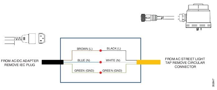
Configuring the Access Point
For information on configuring the access point, see the following documents:
- For Lightweight Access Points and Mesh Access Points, see the Cisco Wireless LAN Controller Configuration Guide, which is available at:
http://www.cisco.com/c/en/us/td/docs/wireless/controller/7-6/configuration-guide/b_cg76.html
- For Mesh Access Points, see the Cisco Wireless Mesh Access Points, Design and Deployment Guide, which is available at:
http://www.cisco.com/c/en/us/td/docs/wireless/technology/mesh/7-6/design/guide/mesh76.html
- For Access Points in autonomous mode, see the Cisco Aironet Access Points Configuration Guide for Cisco IOS Software, which is available at:
http://www.cisco.com/c/en/us/td/docs/wireless/access_point/15-3-3/configuration/guide/cg15-3-3.html
What to Do Next
When you power up a MAP that is not connected to a wired Ethernet, fiber-optic, or cable network to the controller, the access point uses the Cisco Adaptive Wireless Path Protocol (AWPP) to bind to another mesh access point (MAP) with the best path to a root access point (RAP) connected to the wired network to a controller. The access point sends a discovery request when powered up. If you have configured the access point in the controller correctly, the controller sends back a discovery response to the access point. When that happens, the access point sends out a join request to the controller, and the controller responds with a join confirmation response. Then the access point establishes a Control And Provisioning of Wireless Access Points (CAPWAP) connection to the controller and gets the shared secret configured on the controller.
Refer to the Cisco Wireless LAN Controller Configuration Guide for more information on configuring, monitoring, and operating your access points.
 Feedback