Test Bed 2: Call Flows and Redundancy
Available Languages
Table Of Contents
Test Bed 2: Call Flows and Redundancy
Cisco Unified Communications Manager Post-Routed Call Flow
Description of Cisco Unified Communications Manager Post-Routed Call Flow
Cisco Unified Communications Manager Post-Routed Call Flow at Specific Sites
Cisco Unified Customer Voice Portal Post-Routed Call Flow
Description of Cisco Unified Customer Voice Portal SIP Call Flow
Cisco Unified Customer Voice Portal Post-Routed Call Flow at Specific Sites
Description of Parent/Child Call Flows
Parent/Child Call Flow at Specific Sites in Test Bed 2
Cisco Outbound Option Call Flow
Description of Cisco Outbound Option Call Flows
Cisco Outbound Option Call Flow at Specific Sites
Failure, Failover and Recovery
Failure without Failover Testing
Private Connection Between Roggers
Test Bed 2: Call Flows and Redundancy
This topic provides configuration information for a variety of sample call flows that were tested and verified in Test Bed 2 in the contact center environment for Cisco Unified Communications System Release 8.5(1). This topic also describes specific test cases that were executed as a part of Cisco Unified Communications System Release 8.5(1) failover testing.
This topic contains the following sections:
•
Failure, Failover and Recovery
Tested Call Flows
The Parent and Child test bed handles the following types of call flows:
•
•
•
•
Cisco Unified Communications Manager Post-Routed Call Flow
Cisco Unified Communications Manager takes care of the switching requirements of the Cisco Unified Contact Center Enterprise (Unified CCE) system.
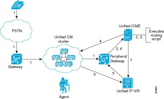
This section describes a sample Unified Communications Manager Post-Routed call flow that was tested and verified. In this sample Unified Communications Manager Post-Routed call flow model, the customer call comes in first to the Unified Communications Manager. The Unified Communications Manager can receive the call from the PSTN network on a Cisco Voice Gateway.
The Unified Communications Manager informs Unified ICME of the new call to request routing information. ICME, using its routing logic, determines the appropriate target (agent or peripheral that is the Unified IP IVR).
In this call flow model, Unified ICME responds to the Unified Communications Manager with a routing label for Unified IP IVR and then sends the call to the Unified IP IVR. The Unified IP IVR prompts the user for Caller Entered Digits (CED). Based on the caller's response, Unified ICME looks for an available agent in the appropriate skill group. If no agents are available, then the call remains in Unified IP IVR for queueing. Once the agent becomes available, Unified ICME redirects the call to that agent.
Description of Cisco Unified Communications Manager Post-Routed Call Flow
1.
2.
3.
4.
Note5.
6.
7.
Figure 1 shows how the Unified Communications Manager Post-Routed call is handled prior to agent involvement.
Figure 1 Unified Communications Manager Post-Routed Call Flow
Agent Is Available (Scenario A)
1.
–
–
2.
3.
Note4.
5.
6.
7.
8.
Figure 2 shows how the Unified Communications Manager Post-Routed call is handled when an agent is available (Scenario A).
Figure 2 Unified Communications Manager Post-Routed Call Flow (Agent is Available)

Agent Is Not Available (Scenario B)
1.
2.
3.
4.
–
–
5.
Figure 3 shows how the Unified Communications Manager Post-Routed call is handled when an agent is not available (Scenario B).
Figure 3 Unified Communications Manager Post-Routed Call Flow (Agent is Not Available)

Cisco Unified Communications Manager Post-Routed Call Flow at Specific Sites
Note that the site-specific information described in this section is not represented in the graphics shown in Figure 1, Figure 2, and Figure 3.
The sample Unified Communications Manager Post-Routed call arrives in Site1/Site4 but is handled by agents in Site2, Site3, and Site7:
1.
2.
3.
4.
5.
6.
Configuration of Components
For installation and configuration documentation on these components, see Components Installation and Configuration Guides at:
http://www.cisco.com/cisco/web/docs/iam/unified/ipcc851/Component_Installation_and_Configuration_Guides.htmlInformation related to configuring the various components involved in handling the Unified Communications Manager Post-Routed call flow is available at: http://docwiki.cisco.com/wiki/Category:Contact_Center_System_Configurations
Cisco Unified Customer Voice Portal Post-Routed Call Flow
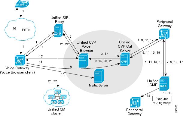
Cisco Unified Customer Voice Portal (Unified CVP) in the comprehensive mode is deployed to provide IVR queueing and call treatment. The Unified CVP comprehensive deployment involves the either a SIP or H.323 ingress gateway, Unified CVP Call Server (co-located H.323 Service and Unified CVP Application Server), an IOS Voice Browser (VXML-enabled), and the Unified ICME components. Other involved components include the Gatekeeper, Unified Communications Manager, HTTP Media Server, and Cisco Unified Customer Voice Portal Studio (Unified CVPS) server.
This section describes a sample Unified CVP Post-Routed call flow that was tested and verified in this test environment. In a typical Unified CCE system with Unified CVP (comprehensive mode), there is no pre-routing of customer calls. Calls arrive immediately at the peripheral (Unified CVP) that issues a ROUTE_REQUEST message to Unified ICME. Unified ICME begins its routing script and the caller can experience one of these segments:
•
•
Thereafter, the agent may transfer the call to a second agent or supervisor, which might include another queued segment if the second agent is not yet available.
Description of Cisco Unified Customer Voice Portal SIP Call Flow
1.
2.
3.
4.
5.
6.
7.
8.
9.
10.
11.
12.
13.
14.
15.
16.
17.
18.
Figure 4 is a graphical representation of the Unified CVP Post-Routed call flow as described up to this point (steps 1-18).
Figure 4 Unified CVP Post-Routed Call Flow

19.
20.
21.
22.
23.
24.
a.
b.
c.
Figure 5 is the second graphical representation of the Unified CVP Post-Routed call flow describing the rest of the call flow (steps 20-24).
Figure 5 Unified CVP Post-Routed Call Flow

Cisco Unified Customer Voice Portal Post-Routed Call Flow at Specific Sites
Note that the site-specific information described in this section is not represented in the graphics shown in Figure 4 and Figure 5.
The sample Unified CVP Post-Routed call arrives at the branch office sites and retail centers (not at the data centers) and is handled by agents at the remote sites. Note that the Unified CVP Call Servers are located at the data centers.
1.
2.
3.
4.
Configuration of Components
For installation and configuration documentation on these components, see Components Installation and Configuration Guides at:
http://www.cisco.com/cisco/web/docs/iam/unified/ipcc851/Component_Installation_and_Configuration_Guides.htmlInformation related to configuring the various components involved in handling the Unified CVP Post-Routed call flow is available at: http://docwiki.cisco.com/wiki/Category:Contact_Center_System_Configurations
Parent/Child Call Flow
The Cisco Unified Contact Center Gateway Enterprise (Unified CCGE) feature, which includes the parent Unified Intelligent Contact Management Enterprise (Unified ICME) system, the child Unified Contact Center Enterprise (Unified CCE) system and the child Unified CCX system, allows the children to appear as traditional ACDs connected to the Unified ICME system. The following Peripheral Gateways are used in this deployment:
•
•
NoteParent and Child Systems Relationships
The systems in an Unified CCGE deployment play different roles. The following terms describe the relationship between these roles:
•
•
Unified SCCGs. The Unified CCX can also be set up to function as an ACD.The parent system does the following:
•
•
•
The child system does the following:
•
•
•
For detailed information on the parent and child model, see the Cisco Contact Center Gateway Deployment Guide for Cisco Unified ICME/CCE/SCCE/CCX at:
http://www.cisco.com/en/US/docs/voice_ip_comm/cust_contact/contact_center/ipcc_enterprise/ipccen terprise8_0_1/installation/guide/ipcc80gtwy.pdfDescription of Parent/Child Call Flows
In the Parent System
1.
2.
3.
4.
5.
6.
7.
8.
9.
10.
11.
12.
13.
14.
15.
16.
17.
18.
–
–
19.
20.
21.
22.
–
–
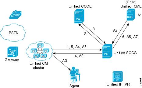
Figure 6 is the graphical representation of the Parent/Child call flow. Note that while the Unified CVP Call Browser, CVP SIP subsystem service, and Media Server are represented as separate entities, they are all on the same physical Unified CVP Call server.
Figure 6 Parent/Child Call Flow (in the Parent System)
In the Child System
1.
2.
3.
4.
5.
6.
7.
a.
b.
Agent is Available at the Child Site (Scenario A)
1.
1.
–
–
2.
3.
4.
5.
6.
Figure 7 shows how the Parent/Child call flow is handled by the child system when an agent is available (Scenario A).
Figure 7 Parent/Child Call Flow (Child System with Agent Available)
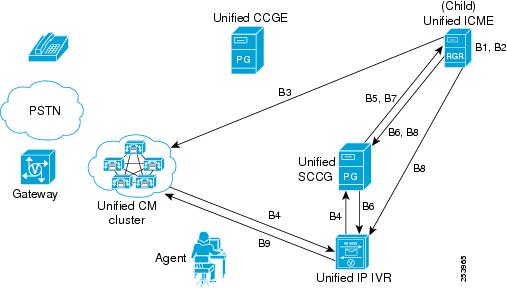
Agent is Not Available at the Child Site Using IP IVR (Scenario B)
1.
2.
3.
Unified IP IVR, the dialed number is a CTI route point that is owned by the Unified IP IVR user.
Note4.
5.
6.
7.
8.
–
–
9.
Figure 8 is the graphical representation of steps B1-B9 of the Parent/Child call flow describing the call treatment provided by the child system when an agent is not available.
Figure 8 Parent/Child Call Flow (Child System with Agent Not Available)
Agent is Not Available at the Child Site Using CVP (Scenario C)
1.
2.
3.
4.
5.
6.
a.
b.
c.
Parent/Child Call Flow at Specific Sites in Test Bed 2
Note that the site-specific information described in this section is not represented in the graphics in this section.The sample Parent/Child call arrives at the parent sites (Site1/Site4) in Test Bed 2 and is routed by the parent systems (Unified ICME) to the child systems (Unified CCE). The call is handled by agents at the child sites.
At the Parent Site:
1.
2.
3.
4.
5.
At the Child Site:
1.
2.
3.
Configuration of Components
For installation and configuration documentation on these components, see Components Installation and Configuration Guides at:
http://www.cisco.com/cisco/web/docs/iam/unified/ipcc851/Component_Installation_and_Configuration_Guides.htmlInformation related to configuring the various components involved in handling the Parent and Child call flow is available at: http://docwiki.cisco.com/wiki/Category:Contact_Center_System_Configurations
Cisco Outbound Option Call Flow
Cisco Outbound Option (Outbound Option) is a feature of Unified ICME that provides outbound dialing functionality along with existing inbound capabilities of the Unified ICME software. With Outbound Option, contact centers can be configured for automated outbound activities. Agents who are not busy handling inbound requests can perform outbound calls.
Call blending and predictive dialing offer a way to increase resource utilization and increase productivity in a contact center. Outbound Option enables contact center managers in need of outbound campaign solutions to take advantage of the enterprise view that Unified ICME maintains over agent resources.
This section describes a sample Outbound Option Post-Routed call flow that was tested and verified in this test environment.
Description of Cisco Outbound Option Call Flows
Using Outbound Dialer
1.
2.
3.
4.
5.
6.
7.
8.
9.
10.
Figure 9 is a graphical representation of the Outbound Option call flow (using Outbound Dialer) as described here.
Figure 9 Outbound Option Call Flow (using Outbound Dialer)

Cisco Outbound Option Call Flow at Specific Sites
Note that the site-specific information described in this section is not represented in the graphics in this section. In the Parent/Child test bed (Test Bed 2), the Outbound Option calls are handled by a set of dedicated agents in Site8.
The Outbound Option call flow is handled in the test bed as follows:
1.
2.
3.
4.
5.
6.
Configuration of Components
For installation and configuration documentation on these components, see Components Installation and Configuration Guides at:
http://www.cisco.com/cisco/web/docs/iam/unified/ipcc851/Component_Installation_and_Configuration_Guides.htmlInformation related to configuring the various components involved in handling the Outbound Option call flow is available at: http://docwiki.cisco.com/wiki/Category:Contact_Center_System_Configurations
Failure, Failover and Recovery
This topic includes the following section:
•
–
Failure without Failover Testing
This section discusses the failover testing that was done with contact center components that did not provide redundancy capabilities in the event of a failure.
Private Connection Between Roggers
Pre-Test Conditions
The following describes the test conditions for this test:
•
•
•
•
•
Test
The following describes the failover testing that was performed for the private connection between the Roggers (without a backup connection):
1.
2.
3.
4.
Results
The following results were verified in this test:
After the Private Link Failure
•
•
•
•
•
•
After the Private Link was Restored
•
•
•

 Feedback