Planning for Provisioning

Table Of Contents

Planning for Provisioning

Software Release Version 7.4(x)

Planning Routes to Other Switches

Defining SS7 Network Addresses

Defining Linksets

Evaluating Linkset Properties

Disabling the Message Priority Feature

Defining SS7 Subsystems

Defining SS7 Routes

Planning the SS7 Signaling Service

Evaluating SS7 Signaling Service Properties

Planning SS7 Signaling Links

Planning Network Cards for Cisco SLT Communications

Planning Ethernet Interfaces for Cisco SLT Communications

Planning TDM Interfaces for Communications

Planning A-Links Through Cisco SLTs

Planning A-Links to Signaling Points

Planning F-Links Through Cisco SLTs

Planning F-Links to Signaling Points

Planning PRI Backhaul Links

Planning Media Gateway Control Links

Planning Media Gateway External Nodes

Planning for the Media Gateway Signaling Service

Planning Network Cards for Media Gateway Communications

Planning Ethernet Interfaces for Media Gateway Communications

Planning TDM Interfaces for Media Gateway Communications

Planning IP Links

Provisioning Trunk Groups and Trunks

Provisioning Trunk Groups and Trunks Using MML Commands

Provisioning Trunk Groups and Trunks Using an Imported File

Provisioning a Nailed Configuration

Adding Nailed Trunks

Creating the Trunk Group

Populating a Trunk Group File

Populating a Trunk File

Route Analysis

Creating a Routing Trunk Group

Provisioning a Routing Trunk Group Using MML Commands

Provisioning a Routing Trunk Group Using an Imported File

Associating a Route with a Trunk Group

Creating a Route List

An MML Example for Creating a Routing File


Planning for Provisioning


This chapter describes how to plan for system configuration. Before you can configure the system, you must determine the following:

The system components you will be defining in the Cisco MGC software

The configuration parameter values you will assign to each component

The software release version installed in the Cisco MGC.

Software Release Version 7.4(x)

The software release version installed in the Cisco MGC will determine the steps that you will take for the tasks described in this chapter. Currently software Release 7.4(x), also called Drop 4, is discussed in this chapter.

This chapter describes the following tasks:

Planning Routes to Other Switches

Planning SS7 Signaling Links

Planning Media Gateway Control Links

Route Analysis

The order in which you configure components is important. Many components refer to other components that must be defined first. When you create the components described in this chapter, be sure to create them in the order described in this chapter.


Note The virtual switch node can use two Cisco MGC hosts for maximum availability. The differences in the active and standby media gateway controllers (MGC) are defined in the XECfgParm.dat file, which is configured during software installation. The configuration planned in this chapter applies to both of the Cisco MGC hosts. You create one configuration for one exchange and apply that configuration to both Cisco MGC hosts.


Tip This chapter provides blank tables you can use to plan the configuration components. While some tables provide room to define many components, other tables allow you to plan just one component. Before you start your planning, copy the tables and write on the copies. This way, you can make additional copies later if you need them.


Planning Routes to Other Switches

Figure 2-1 shows the software components that must be configured to connect the Cisco MGC to an external switch.

Figure 2-1 SS7 Signaling Route Configuration Components

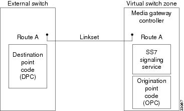
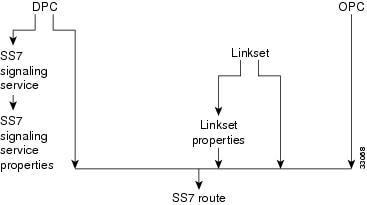
Figure 2-2 shows the order in which the components shown in Figure 2-1 must be configured.

Figure 2-2 SS7 Signaling Route Component Hierarchy

To configure routes between the Cisco MGC and a destination device (for example, a switch), you must do the following:


Step 1 Define the SS7 network addresses (point codes) of devices along the signaling route.

Step 2 Define linksets.

Step 3 Override linkset properties (if necessary).

Step 4 Define an SS7 subsystem for each pair of STPs.

Step 5 Define an SS7 signaling service to support the signaling route.

Step 6 Override the SS7 signaling service properties (if necessary).

Step 7 Define the SS7 signaling route.


Note When provisioning, fully define all components (see Figure 2-2) before deploying a configuration.


Note For properties not described in this chapter, refer to the Cisco Media Gateway Controller Software Release 7 Reference Guide.


Defining SS7 Network Addresses

The first step in planning signaling routes is to identify the SS7 network devices that link the Cisco MGC to remote switches. To identify these network devices, you must configure the point codes (see Table 2-1 for a list of point code parameter descriptions), which serve as SS7 network addresses. The point codes must be unique within the SS7 network. You must get these point codes from your SS7 network administrator.

Point codes are necessary for the following network devices:

Cisco MGC—Within the Cisco MGC software, the Cisco MGC's point code is called the origination point code (OPC). Table B-4 serves as a form where you can plan the OPC configuration for your Cisco MGC.

STP—Within the Cisco MGC software, the point code for each STP with which the controller communicates is called the adjacent point code (APC). Table B-6 serves as a form where you can plan the APCs for your Cisco MGC.

Destination switch—Within the Cisco MGC software, a remote device's point code is called a destination point code (DPC). You need a point code for each remote switch with which the MGC node will communicate. Table B-5 serves as a form where you can plan the DPCs for your Cisco MGC.

When configuring a Cisco MGC, you must enter a point code and a point code type for each Cisco MGC, along with the network address and the network indicator. The point code type is OPC and the point code address is a value in the format x.x.x. For example, 8.232.72. The two periods separating the three numeric labels are required, and the numeric labels must be entered in decimal values. If your service provider issues these numbers using binary or hexadecimal values, you must convert them to decimal.


Note The point code examples used in this document follow the ANSI SS7 point code format.


For configuring point codes for remote switches, the point code type is DPC. Each point code for an STP is an APC, and the STP point code type is APC. The point code values for DPCs and APCs use the same format (x.x.x) as for OPCs.

To define SS7 network addresses, you must configure the following component types:

CMM Component Name: PointCode

MML Component Name: PTCODE

CMM Component Name: APC

MML Component Name: APC

Table 2-1 Point Code Parameter Descriptions

MML Parameter Name
CMM Parameter Name
Description

NAME

MML name

Unique name for this point code. Enter as many as 10 alphanumeric characters (or 20 alphanumeric characters for Release 7.4) and enclose in straight quotes. Hyphens (-) can be used.

NETADDR

Network address

SS7 network address in dotted notation.

NETIND

Network indicator

The network indicator assigned by the network administrator.

DESC

Description

Text description of this point code. Enter as many as 128 characters and enclose in straight quotes.


Defining Linksets

After you determine the point codes for your network devices, you must define the linksets that connect each MGC node directly to a remote switch or indirectly through an STP. A linkset is the group of all communication links connecting an MGC node to a specific SSP or STP. When two STPs are defined as mates within the Cisco MGC software, the Cisco MGC can use either linkset to connect to the SS7 signaling network.

Table 2-2 lists the configuration parameters you must define for each linkset, and Table B-7 serves as a form that you can use to define linksets.

To define linksets, you must configure the following component types:

CMM Component Name: LinkSet

MML Component Name: LNKSET


Note When configuring linksets for STP connections, you will usually configure two linksets for each pair of STPs.


Table 2-2 Linkset Configuration Parameter Descriptions

MML Parameter Name
CMM Parameter Name
Description

NAME

MML name

Unique name for this linkset. Enter as many as 10 characters (or 20 alphanumeric characters for Release 7.4) and enclose in straight quotes. Hyphens (-) can be used.

APC

Adjacent point code/point code

Adjacent point code or destination point code. For linksets that connect directly to an SSP, enter the MML name of a previously defined destination point code. For linksets that connect to a Cisco SLT, enter the MML name of a previously defined adjacent point code.

TYPE

Transport type

Enter TDM for linksets that connect directly to an SSP, or enter IP for linksets that connect to Cisco SLTs. The default is TDM.

PROTO

Protocol family

Enter one of the following:

SS7-ANSI

SS7-ITU

SS7-China

SS7-Japan

SS7-UK

DESC

Description

Text description of this linkset. Enter as many as 128 characters and enclose in straight quotes.


Table 2-3 Linkset Configuration Parameters

Name
APC or DPC
Type
Proto
Desc


Evaluating Linkset Properties

Linkset properties serve as additional configuration parameters you can use to tune linkset communications. Table 2-4 lists the default properties assigned to linksets. These properties apply to all linksets you create. You do not have to enter these values.

To change linkset properties, you must configure the following component types:

CMM Component Name: Properties (access from the LinkSet component window)

MML Component Name: LNKSETPROP

Table 2-4 Linkset Property Descriptions 

MML Parameter Name
Default Value
Unit
Description

mtp2AermEmgThr1

1

Messages

Alignment error rate monitor threshold duration for emergency operation. Value: 1 message.

mtp2AermNrmThr

4

Messages

Alignment error rate monitor threshold duration for normal operation. Value range: 1 through 4 messages.

mtp2CongDiscard

false


Discard frames upon entering congestion at MTP2. Set to true or false.

mtp2LssuLen

1 for all except SS7-JAPAN=2

Octets

Link status signal unit, status field length. Specify either 1 or 2.

mtp2MaxAlignRetries

5

Attempts

Maximum number of attempts to align link before declaring it Out-of-Service (OOS). Value range: 1 through 10 attempts.

Note The Cisco MGC also reattempts link alignment every 5 seconds.


mtp2MaxMsuFrmLen

272

Octets

Maximum frame length of a C7 message signal unit. Specify 62 or 272.

mtp2MaxOutsFrames

127 for all except SS7-JAPAN=40

Frames

The maximum number of outstanding frames that can be sent without receiving an acknowledgment. Value range: 1 through 127.

mtp2ProvingEmgT4

6 for all except SS7-JAPAN=302

Tenths of a second

Emergency proving period. Value range: 5 through 7 tenths of a second.

mtp2ProvingNormalT4

23 for all except SS7-JAPAN=30

Tenths of a second

Normal proving period. Value range: 1 through 3 seconds.

mtp2SuermThr

64 for all except SS7-JAPAN=16384

Frames

Signal unit error rate monitor threshold for emergency operation. Value range: 1 through 16385.

mtp2T1

SS7-ANSI=130
SS7-UK=450
SS7-CHINA=450
SS7-ITU=450
SS7-JAPAN=150

Tenths of a second

Maximum period in Aligned/Ready state before return to Out-of-Service state. Value range: 12 through 16 seconds (for ANSI) or 40 through 50 seconds (for BT, CHINA, and ITU).

mtp2T2

SS7-ANSI=115
SS7-UK=250
SS7-CHINA=250
SS7-ITU=250
SS7-JAPAN=50

Tenths of a second

Maximum period in Not Aligned state before return to Out-of-Service state. Value range: 5 through 30 seconds.

mtp2T3

SS7-ANSI=115
SS7-UK=20
SS7-CHINA=20
SS7-ITU=20
SS7-JAPAN=30

Tenths of a second

Maximum period in Aligned state before return to Out-of-Service state. Value range: 5 through 14 seconds (for ANSI) or 1 through 2 seconds (for BT, CHINA, and ITU).

mtp2T5

1 for all except SS7-JAPAN=2

Thousandths of a second

Period for sending a SIB3 message to far-end.
Value range: 80 through 120 seconds.

mtp2T6

SS7-ANSI=30
SS7-UK=60
SS7-CHINA=60
SS7-ITU=60
SS7-JAPAN=30

Tenths of a second

Remote congestion timer. If congestion is not cleared before expiration of this timer, the link fails. Value range: 1 through 6 seconds (for ANSI) or 3 through 6 seconds (for BT, CHINA, and ITU).

mtp2T7

10 for all except SS7-JAPAN=20

Tenths of a second

MTP2 acknowledgment timer. On timer expiration, the link fails and an "excessive delay of acknowledgment" management message is generated. Value range: 0.5 through 2 seconds (for BT, CHINA, and ITU).

mtp3ApcMtpRstrtT28

SS7-ANSI=10

Tenths of a second

Overall restart timer for signaling point adjacent to one whose MTP restarts. Value range: 3 through 35 seconds (for ANSI only).

mtp3DlnkConnAckT7

10 for all except SS7-JAPAN=20

Tenths of a second

Waiting for signaling data link connection acknowledgment.
Value range: 1 through 2 seconds, or through 5 seconds when you are connecting over a Cisco SLT.

mtp3FrcUnhT13

10 for all except SS7-JAPAN=0

Tenths of a second

Waiting for force uninhibited. Value range: 0.8 through 1.5 seconds.

mtp3InhAckT14

20 for all except SS7-JAPAN=0

Tenths of a second

Waiting for inhibit acknowledgment. Value range: 2 through 3 seconds.

mtp3LocInhTstT20

SS7-ANSI=900

Tenths of a second

Waiting to repeat local inhibit test.
Value range: 90 through 120 seconds (for ANSI only).

mtp3MaxSltTries

2 for all except SS7-JAPAN=0

Messages

Maximum number of retries of signaling link test message. If MTP3 does not receive a response after two signaling link test messages, the system fails the link. Value range: 1 through 5.

mtp3MsgPriority

SS7-ANSI=2
SS7-UK=1
SS7-CHINA=1
SS7-ITU=2 4
SS7-JAPAN=2


Message priority of management messages for congestion periods.
Value range: 0 through 3. Priority 1 indicates no congestion priorities. Priorities greater than 1 indicate multiple congestion priorities. Priority 3 is the highest priority.

mtp3MtpRstrtT20

900 for all except SS7-JAPAN=0

Tenths of a second

Overall MTP restart timer at the signaling point whose MTP restarts. Value range: 59 through 61 seconds.

Note This parameter is for BT, CHINA, and ITU.

mtp3ApcMtpRstrtT21

SS7-UK=640
SS7-CHINA=10
SS7-ITU=640
SS7-JAPAN=0

Tenths of a second

Overall MTP restart timer at an SP adjacent to an SP whose MTP restarts. Value range: 63 through 65 seconds.

Note This parameter is for BT, CHINA, and ITU.

mtp3LocInhTstT22

3000 for all except SS7-JAPAN=0

Tenths of a second

Waiting to repeat local inhibit test.
Value range: 3 through 6 minutes.

mtp3MtpRstrtT24

SS7-ANSI=60

Tenths of a second

Overall MTP restart timer for local MTP restart. Value range is network-dependent.

mtp3RepeatRstrtT26

SS7-ANSI=150

Tenths of a second

Traffic restart waiting message at local MTP restart.
Value range: 12 through 15 seconds.

mtp3TfrUsed

false


Transfer restricted procedure is enabled (true) or disabled (false). Set to true or false.

mtp3TraSnT29

SS7-ANSI=600

Tenths of a second

Timer started when traffic restart allowed is sent in response to unexpected traffic restart allowed or traffic restart waiting.
Value range: 60 through 65 seconds.

mtp3tstSltmT1

SS7-ANSI=60
SS7-UK=50
SS7-CHINA=50
SS7-ITU=50
SS7-JAPAN=0

Tenths of a second

Waiting for signaling link test acknowledgment message. This must be greater than the value in mtp2T6. Value range: 0 through 12 seconds.

mtp3tstSltmT2

SS7-ANSI=600
SS7-UK=300
SS7-CHINA=300
SS7-ITU=300
SS7-JAPAN=0

Tenths of a second

Interval for sending signaling link test message.
Value range: 0 through 90 seconds.

mtp3UnhAckTl2

10 for all except SS7-JAPAN=0

Tenths of a second

Waiting for uninhibited acknowledgment.
Value range: 0.8 through 1.5 seconds.

mtp3T0

SS7-JAPAN=200

Tenths of a second

Not used.

mtp3T7

SS7- JAPAN=20

Tenths of a second

Waiting for signaling data link connection acknowledgement. Value range: 1 through 20 seconds.

mtp3T12

SS7-JAPAN=0

Tenths of a second

Waiting for signaling data link connection acknowledgement. Value range: 500 through 1500 milliseconds.

mtp3T13

SS7-JAPAN=0

Tenths of a second

Same as mtp3FrcUnhT13.

mtp3T14

SS7-JAPAN=0

Tenths of a second

Same as mtp3InhAckT14.

mtp3T20

SS7-JAPAN=0

Tenths of a second

Same as mtp3MtpRstrtT20.

mtp3T21

SS7-JAPAN=0

Tenths of a second

Same as mtp3ApcMtpRstrtT21.

mtp3T22

SS7-JAPAN=0

Tenths of a second

Same as mtp3LocInhTstT22.

reference

SS7-ANSI=
ANSI92
SS7-UK=ITU92
SS7-CHINA=
ITU92
SS7-ITU=ITU92
SS7-JAPAN=Japan


Denotes versions for protocol standards supported for MTP.
for SS7-ANSI: options ANSI92, ANSI96
for SS7-UK, SS7-CHINA, SS7-ITU: options ITU88 and ITU92 for SS7-JAPAN: options Japan, TTC.

rudpAck

enable


Not used.

rudpKeepAlives

enable


Not used.

rudpNumRetx

3


The maximum number for Retransmission count.
Value range: 1 through 100.

rudpWindowSz

32


The maximum number for Unacknowledged Segments in the RUDP window.
Value range: 2 through 64.

rudpRetxTimer

3

Tenths of a second

The Retransmission timeout. Value range: 2 through 100.

rudpSdm

enable


Not used.

1 The mtp2 parameters are used with directly connected SS7 signaling links (for example, ITK or PTI cards).

2 All timer values are expressed in tenths of a second. For example, 130 = 13 seconds.

3 SIB = Status indication busy

4 You cannot configure the SS7-ITU.mtp3MsgPriority property in release 7.4(x) using MML or CMM. Refer to the following section, "Disabling the Message Priority Feature," for detailed instructions.


Disabling the Message Priority Feature

The SS7-ITU.mtp3MsgPriority property defines the priority of management messages for congestion periods. A value of 1 disables the message priority feature and automatically sets the A/B bits to 0 (zero). Properties greater than 1 indicate multiple congestion priorities.


Note You cannot configure the SS7-ITU.mtp3MsgPriority property in release 7.4(x) using MML or CMM.


Perform the following steps to disable the message priority feature:


Step 1 Complete the following steps on both the active and standby machine:

a. cd /opt/CiscoMGC/etc.

b. vi properties.dat.

c. Change the value of SS&-ITU.mtp3MsgPriority to 1.

d. cp properties.dat active_link/.

Step 2 Stop and then restart the standby machine.

Step 3 Perform a manual switchover.

Step 4 Stop and then restart the new standby machine.


Defining SS7 Subsystems

In the Cisco MGC, an SS7 subsystem is used to mate two STPs or to define SS7 subsystems that access IN services. When two STPs are defined as mates within the Cisco MGC software, the software can use either STP for communications with an external switch. Table 2-5 lists the configuration parameters you can use to configure an SS7 subsystem, and Table B-13 serves as a form that you can use to plan for the SS7 subsystems.


Note You must define one SS7 subsystem for each STP to which the MGC node connects.


To define an SS7 subsystem, you must configure the following component types:

CMM Component Name: SS7SubSys

MML Component Name: SS7SUBSYS

For mated STPs, the subsystem defined for each STP defines the other STP as the mate using the MATEDAPC parameter.

Table 2-5 SS7 Subsystem Configuration Parameter Descriptions 

MML Parameter Name
CMM Parameter Name
Description

NAME

MML name

Unique name for this subsystem. Enter as many as 10 alphanumeric characters (or 20 alphanumeric characters for Release 7.4) and enclose in straight quotes. Hyphens (-) can be used.

SVC

Adjacent point code

Adjacent point code for an STP. The MML name or index of the APC if TRANSPROTO is SCCP. Or the MML name or index of TCAPOverIP service for IN trigger services if TRANSPROTO is TCPIP. Enter the MML name of a previously defined APC.

MATEDAPC

Mated Adjacent Point Code

Adjacent point code for an STP mate. Enter the MML name of previously defined APC. Only used when mating STPs, not when creating Advanced Intelligent Network (AIN) subsystems.

PRI

Priority

Priority. Enter an integer that is greater than 0 and less than 4. One (1) is the highest priority level. When two subsystems share the same priority level, traffic is shared by both subsystems. Not used when mating STPs.

Default = 1.

PROTO

Protocol family

Protocol family. When mating STPs, only the SS7 variant is allowed.

SS7-ANSI—When creating an AIN subsystem.

SS7-ITU—When creating an AIN subsystem.

SS7-China—When mating an STP pair.

SS7-Japan—When mating an STP pair.

SS7-UK—When mating an STP pair.

If the SVC is an APC, SCCP should not be used (SCCP is not used when mating STP pairs). If the SVC is a TCAPoverIP service, then TCPIP should be used

SSN

Subsystem number

Subsystem number. Enter an integer from 0 to 255. When mating STPs, SSN = 0. When using IN services, SSN can be set to a value greater than 0.
Default = 0.

STPSCPIND

STP-SCP index

STP/SCP index. Enter an integer greater than 0. When mating STPs = 0. Default = 0. Not used when mating STPs.

TRANSPROTO

Transport protocol

Transport protocol. Enter the transport protocol of this subsystem. When mating STPs = SCCP. Values: SCCP or TCPIP. Not used when mating STPs.


Defining SS7 Routes

The final step in planning routes is to define the SS7 routes themselves. Routes are defined in terms of the point codes along the path and the linksets that lead from the MGC node through the STPs to each DPC. Table 2-6 describes the configuration parameters you can use to configure routes, and Table B-10 serves as a form for you to define your routes. It is a good practice to define two routes to each remote switch. Each route should pass through a different STP in a mated pair. The linkset parameter, LNKSET, defines which STP a route will follow.

To define an SS7 route, you must configure the following component types:

CMM Component Name: SS7Route

MML Component Name: SS7ROUTE

Table 2-6 SS7 Route Configuration Parameter Descriptions 

MML Parameter Name
CMM Parameter Name
Description

NAME

MML name

Unique name for this route. Enter as many as 10 alphanumeric characters (or 20 alphanumeric characters for Release 7.4) and enclose in straight quotes. Hyphens (-) can be used.

OPC

Originating point code

Origination point code. Enter the MML name of a previously defined origination point code for this MGC node.

DPC

Destination point code

Destination point code. Enter the MML name of a previously defined destination point code for a remote switch.

LNKSET

Link set

Linkset that leads to the destination device. Enter the MML name of a previously defined linkset.

PRI

Priority

SS7 route priority. Enter an integer that is greater than 0. One (1) is the highest priority level. When two SS7 routes share the same priority level, traffic is shared by both routes.

Default = 1.

DESC

Description

Text description of this route. Enter as many as 128 characters and enclose in straight quotes.


Planning the SS7 Signaling Service

The SS7 signaling service is the Cisco MGC software service that communicates over the route with a remote switch. You must define a separate service for each remote switch. Table 2-7 describes each of the SS7 signaling service parameters and provides space for you to plan the configuration of one service. Table B-19 serves as a form for you to define your signaling services.

To define an SS7 signaling service, you must configure the following component types:

CMM Component Name: SigSS7

MML Component Name: SS7PATH

Table 2-7 SS7 Signaling Service Configuration Parameter Descriptions 

MML Parameter Name
CMM Parameter Name
Value
Description

NAME

MML name


Unique name for this signaling service. Enter as many as 10 alphanumeric characters (or 20 alphanumeric characters for Release 7.4) and enclose in straight quotes. Hyphens (-) can be used.

DESC

Description


Text description of this signaling service. Enter as many as 128 characters and enclose in straight quotes.

DPC

Point code


Destination point code. Enter the MML name of a previously defined destination point code.

MDO

MDO file name


Message definition object file name. Choose a valid protocol name. The list contained in Table 2-8 is only a sample. Refer to the release notes for the Cisco MGC software Release 7 for a current list of MDO file names.

SIDE

Side

Network

Q.931 call model side. Enter user for user side or network for network side.
Default = network.

CUSTGRPID

Customer group ID

0000

Customer Group ID. Virtual network identification characters (formerly called the Closed User Group). Values accepted for this field depend on the use of the D channel. Used to retrieve information about this signaling service and which dial plan to use. Enter the four-digit ID. Default = 0000.

CUSTGRP
TBL

Customer group table

Reserved for future use.


Table 2-8 Sample MDO File Names 

Mdo File Name
Protocol Family

DPNSS_BTNR188

DPNSS

ETSI_300_102

ISDNPRI

ETSI_300_102_C1

ISDNPRI

ATT_41459

ISDNPRI

ATT_41459_C2

ISDNPRI

BELL_1268

ISDNPRI

ETSI_300_172

ISDNPRI

BELL_1268_C3

ISDNPRI

JAPAN_INS_1500

ISDNPRI

T113_BELL

SS7-ANSI

NORTEL_IBN7

SS7-ANSI

ANSISS7_SPRINT

SS7-ANSI

ANSISS7_STANDARD

SS7-ANSI

Q721_CHINA

SS7-CHINA

Q721_BASE

SS7-CHINA

Q767_BASE

SS7-ITU

ETSI_300_356

SS7-ITU

BTNUP_BTNR167

SS7-ITU

BTNUP_NRC

SS7-ITU

Q767_SPAN

SS7-ITU

Q761_BASE

SS7-ITU

HKTA_2202

SS7-ITU

ISUPV2_FRENCH

SS7-ITU

ETS_300_121

ISDNPRI

ISUPV2_SWISS

SS7-ITU

ISUPV2_GERMAN

SS7-ITU

FINLAND_5779

SS7-ITU

Q761_AUSTRL

SS7-ITU

ISUPV1_POLI

SS7-ITU

ISUPV2_KPNPB

SS7-ITU

ISUPV2_JAPAN

SS7-JAPAN

ISUPV3_UK

SS7-UK

Q761_BELG_MOBI

SS7-ITU

Q767_ITAL

SS7-ITU

Q767_RUSS

SS7-ITU

EISUP

EISUP


Evaluating SS7 Signaling Service Properties

SS7 signaling service properties serve as additional configuration parameters that you can use to tune signaling service communications. Table 2-9 lists the default properties assigned to an SS7 signaling service. These properties apply to all SS7 signaling services you create. You do not have to enter these values.

To change SS7 signaling service properties, you must configure the following component types:

CMM Component Name: Properties (access from the SigSS7 component window)

MML Component Name: SIGSVCPROP

Table 2-9 SS7 Signaling Service Property Descriptions 

MML Parameter Name
Default Value
Description

adjDestinations

16

Number of adjacent destination point codes. Value range: 1 through 256.

BOrigStartIndex

0

Specifies the starting number analysis digit index for call originations.

Value range: 0 or 1.

BTermStartIndex

0

Specifies the starting number analysis digit index for call terminations.

Value range: 0 or 2.

BothwayWorking

1

Set to 0 to disable both way release / circuit free handling for BTNUP protocol. Value range: 0 or 1.

Note Both the local and remote circuits between which the BothwayWorking parameter operates must be the same type—unidirectional or bidirectional. The Bearer Release Sequence operates differently depending on the type of circuit detected at the local end.

CGBA2

0

Determines if group (0) or individual (1) circuit group blocking acknowledgments (CGBAs) are required before the blocking is considered successful. Only applicable to ANSI SS7, IBN7, and CTUP protocols.Value range: 0 or 1.

CLIDefaultAllowed

false

Adjusts the presentation restricted field in the calling line identity to presentation allowed if set to true. Takes the mapped value from the OCC or TCC protocol side or the default value from the map for this field if false. Value range: true or false.

CLIPEss

0

Set to 1 to force request of calling line identity if not automatically provided. Value range: 0 or 1.

COLDefaultAllowed

false

Adjusts the presentation restricted field in the Connected Line ID to presentation allowed if set to true. Takes the mapped value from the OCC or TCC protocol side or the default value from the map for this field if false. Value range: true or false.

CotInTone

2000 ± 20

Receive tone for continuity test (COT) hardware. The tone to listen for when doing a COT. Enter value in Hz.
Value: 1780 or 2010.

CotListenDuration

60

Maximum period to listen for a COT.
Value range: 0 through 200, specified in milliseconds (should be less than 2 seconds). The T24 timer is set for 60. (No longer used in software Release 7.4.9 and later.)

CotOutTone

2000 ± 20

Transmit tone for COT hardware. The tone that is produced. Enter value in Hz. Value: 1780 or 2010.

CotPercentage

0

Statistical COT. Value range: 0 through 100%.

CotPlayDuration

60

Maximum period in not aligned state before return to Out-of-Service state (should be less than or equal to the CotListenDuration).
Value range: 1 through 200, specified in milliseconds. (No longer used in software Release 7.4.9 and later.)

dialogRange

0

TCAP transaction ID range (for example, 1 through 10000) for a specific subsystem.

0 = entire range.

ExtCOT

Loop

Determines the type of COT handling for the specified destination. Values: 0 (no COT), Loop, or Transponder. (Valid for Release 7.4.7(8) only.)

Note This value is case sensitive.


ForwardCLIinIAM

0

Set to 1 if outgoing IAM should contain the calling line identity, if available. Only applicable for BTNUP when interworking from other protocols.

Value range: 0 or 1.

ForwardSegmentedNEED

1

Set to 0 to disable the forwarding of segmented NEED messages within the BTNUP_NRC protocol. If segmenting is disabled, all mandatory DPNSS information elements will be packed into a single BTNUP NEED message.

Value range: 0 or 1.

GLARE

0

Call Collision Handling. Valid values are:

0 = No glare handling; also known as yield to all double seizures. Call collision results in a REL sent to both calls.

Note Both ends of a link can be given this option. Default = 0.

1 = The Cisco MGC has control of all circuits and any call collisions are handled by this Cisco MGC. It ignores incoming IAMs and proceeds with its own calls as normal.

Note Only one end of a link can be designated with this option.

2 = Highest point code controls the even circuits. Depending on the OPC of the Cisco MGCs, the side that has the higher point code will control the even circuits, while the side with the lower point code will control the odd circuits.

Note Both ends of a link can be given this option.


GLARE (continued)

0

3 = No control. The Cisco MGC specified with this option does not control any circuits. The Cisco MGC accepts incoming IAMs from the side with control.

Note This option is usually used along with the remote node designated with control.


GRA2

0

Determines if paired (0) or single (1) group reset acknowledgments (GRAs) are required before the reset is considered successful. Only applicable to ANSI SS7, IBN7, and CTUP protocols.
Value range: 0 or 1.

GRSEnabled

false

This property is assigned to an SS7 point code type signal path. Enables Group Reset and Blocking procedure at point code initialization. Synchronizes the Cisco MGC bearer channel blocking state with that of the end office.

If True, GRS messages are sent for all CICs associated with the point code.
If False, GRS messages are not sent.

hopCount

1

Default hop count. Value range: 0 or 15 (this indicates the maximum number of hops allowed for SCCP messages).

InternationalPrefix

NULL

International prefix string to be added to the international dialed number when NOA is enabled. Value range: NULL or a numeric string.

layerRetries

2

Number of times to resend request to adjacent layer without getting a response. Value range: 0 through 5. 0 = No retries.

layerTimer

10

Time (in tenths of a second) to wait for a response from adjacent layer (SS7 controller, TCAP to SCCP); tailor when layers are not resident on same processor. Value range: 0 through 10.

0 = Disabled, 10 = 1 second.

maxMessageLength

250

Maximum length of message to MTP3.

This value must be less than the value for mtp2MaxMsuFrmLen.
Value range: 0 through 272.

NationalPrefix

NULL

National prefix string to be added to the national dialed number when normalization is enabled. Value range: NULL or a numeric string.

NatureOfAddrHandling

0

Determines whether or not to do pre-analysis. Value range: 0 or 1.

Normalization

0

Normalization of dialed number to unknown. Set to 0 for disabled and 1 for enabled. Value range: 0 or 1.

OMaxDigits

24

Specifies maximum number of digits to receive for overlap digit processing for call origination from this traffic path.
Value range: 0 through system maximum.

OMinDigits

0

Specifies minimum number of digits to receive for overlap digit processing for call origination from this traffic path.
Value range: 0 through system maximum.

OOverlap

0

Set to 1 to enable overlap signaling for call origination from this traffic path.
Value range: 0 through system maximum.

OverlapDigitTime

6

Overlap interdigit timer. The time to wait for the rest of the digits.
Value range: 0 through 60.

Note If OverlapDigitTimeValue timer is set to more than 30 seconds, other timers expire before this timer.


OwnClli

na

Specifies the common language location identifier (CLLI).

RedirMax

3

Specifies the maximum allowable value of the redirection counter parameter available in some C7 signaling systems before the call is force-released. Used to prevent routing loops in certain applications.
Value range: 0 through system maximum.

restartTimer

10

Time (in tenths of a second) to pause before sending next group of messages to MTP3 after restart. Value range: 0 through 100.

0 = Disabled, 10 = 1 second.

RoutePref

0

Determines the preferred route. Value range: 0 through 9.

0 = No Preference (default) 5 = IP Preferred

1 = ATM Essential 6 = IP Excluded

2 = ATM Preferred 7 = TDM Essential

3 = ATM Excluded 8 = TDM Preferred

4 = IP Essential 9 = TDM Excluded

sendAfterRestart

SS7-ANSI=16

Number of queued messages to send (in one group) to MTP3 after restart end. This value, combined with the sendTimer, controls the amount of data sent to MTP3 after restart ends. If too much data is sent to MTP3 after restart, MTP3 could be flooded. Value range: 0 through 256.

slsTimer

SS7-ANSI=300

Time (in tenths of a second) to maintain the same signal linkset in class 1 (connectionless) messages. This is the type of service provided by the SCCP layer. Value range: 0 through 600.

0 = Disabled, 300 = 30 seconds.

srtTimer

SS7-ANSI=300

Time (in tenths of a second) between sending Subsystem Route Test message (SRT) to remote subsystems. Value range: 0 through 3000.

0 = disabled, 300 = 30 seconds.

sstTimer

SS7-ANSI=300

Time (in tenths of a second) between sending Subsystem Status Test (SST) messages to an unavailable remote subsystem.
Value range: 0 through 3000.

0 = Disabled, 300 = 30 seconds.

standard

SS7-ANSI=
ANSI96,
SS7-ITU=ITU96,

ANSI96,
ITU96,
ANSI92,
ITU92

Version of protocol standard supported for this STP/SCP.

TMaxDigits

24

Specifies maximum number of digits to receive for overlap digit processing for call termination to this traffic path.
Value range: 0 through system maximum.

TMinDigits

0

Specifies minimum number of digits to receive for overlap digit processing for call termination to this traffic path.
Value range: 0 through system maximum.

TOverlap

0

Set to 1 to enable overlap signaling for call termination to this traffic path.
Value range: 0 or 1.

variant

SS7-ANSI=SS7-ANSI, SS7-ITU

SS7 protocol variants supported by local subsystem.

VOIPPrefix

0

A numeric string.


Planning SS7 Signaling Links

Once you have planned your SS7 routes (as described in the "Planning Routes to Other Switches" section), it is time to plan the communication links between the MGC node and the SS7 SPs. SPs are SS7 network nodes, such as STPs and SSPs, with which the Cisco MGC communicates. The Cisco MGC supports two types of SP links: Cisco SLT links and direct SP links. Cisco SLT links use the Cisco SLT to offload MTP 1 and MTP 2 processing to Cisco SLTs. Direct SP links directly link the Cisco MGC to an SP; the Cisco MGC performs all signal processing including MTP 1 and MTP 2 processing.

While linksets define which SP a given route uses, it is the links that carry the communications traffic. Figure 2-3 shows the components you must configure to enable communications with the SPs.

Figure 2-3 Configuring Signaling Linksets and Links

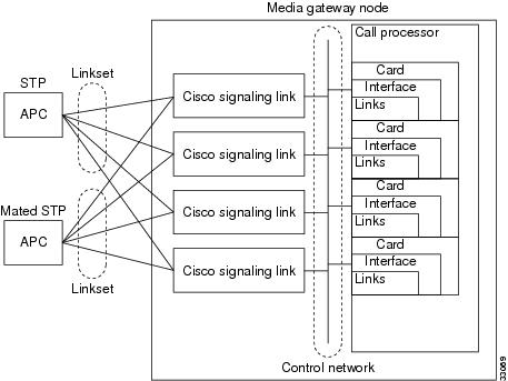
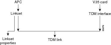
Figure 2-4 shows the order in which the signaling link components must be configured.

Figure 2-4 Signaling Link Component Hierarchy (without Cisco SLTs)

This section describes how to plan for provisioning the signaling link components:

1. Create point codes (APC or DPC)

2. Create linkset

3. Override linkset properties (if necessary)

4. Create adapter

5. Create interface

6. Create TDM link


It is best to plan SS7 routes before you configure links, because you define APCs and linksets when defining routes, and these components must be planned and configured before you can configure links. Because the planning of these components is described in the "Planning Routes to Other Switches" section, these procedures are not repeated here. This section describes how to plan for provisioning the following components:

Cisco MGC cards

Cisco MGC interfaces

Links

The following sections describe how to plan for each of these components.

Planning Network Cards for Cisco SLT Communications

Cards are the hardware cards that are installed on the host computer and provide the network interfaces that communicate with other devices. When planning STP links, you define cards that will communicate with the MGC node Cisco SLTs.


Note In the MGC node, the same cards and interfaces can be used for communication with the Cisco SLTs and media gateways. When this type of configuration is used, separate links are assigned for the Cisco SLT and media gateway communications.


All Cisco MGCs will have at least one Ethernet interface card installed. When configuring the Cisco MGC you need to enter the card name, type, slot number, and IP address information. The IP address information is entered by entering or selecting a system variable name, which is associated with an IP address in the XECfgParm.dat file. You configure the IP addresses and assign them to variables using the procedures in Cisco Media Gateway Controller Software Release 7 Installation and Configuration Guide.

Configuring the Cisco MGC can be performed using either the Cisco Media Gateway Controller Manager (CMM), with its graphical user interface, or the Man-Machine Language (MML), with its command-line interface. In many of the tables, you will see both the MML parameter name and the corresponding CMM parameter name. Refer to "Provisioning Tools" section for a brief explanation of each provisioning tool.

Table 2-1 lists the Cisco MGC interface card parameter definitions. Use Table B-1 to enter the configuration information for the network interface cards installed in your Cisco MGC. For Ethernet cards, the system variable is required for configuration, but the IP address and card slot are not required. The IP address column is provided for convenience.

To provision network cards, you must configure the following component types:

CMM Component Name: Adapter

MML Component Name: CARD

Table 2-10 describes configuration parameters you can use to configure cards, and Table B-1 serves as a form on which you can plan card configurations.

Table 2-10 Card Configuration Parameter Descriptions for Cisco SLT Communications 

MML Parameter Name
CMM Parameter Name
Default Value
Description

NAME

MML name

None

Unique name for this component. Enter as many as 10 alphanumeric characters (or 20 alphanumeric characters for Release 7.4) and enclose in straight quotes. Hyphens (-) can be used.

SLOT

Slot

None

Location of card or adapter within the host machine. Acceptable values depend on the host machine. The first slot is usually 0. Enter a value from 0 through 15.

TYPE

Type

None

The interface card type. Acceptable values are:

ATM_NIC

EN

ITK

V35

DESC

Description

None

Text description of this component point code. Enter as many as 128 characters and enclose in straight quotes.


Planning Ethernet Interfaces for Cisco SLT Communications

Each SS7 link in the MGC node must be associated with an interface component, which must be associated with a network card. The interface represents a physical network connection on the network card.


Note In the MGC node, the same cards and interfaces can be used for communication with the Cisco SLTs and media gateways. When configured this way, separate links are assigned for the Cisco SLT and media gateway communications.


To provision Ethernet interfaces, you must configure the following component types:

CMM Component Name: EnetIF

MML Component Name: ENETIF

Table 2-11 describes the configuration parameters that define an Ethernet interface. Table B-2 serves as a form for you to plan the Ethernet interfaces on your Cisco MGC.

Table 2-11 Ethernet Interface Configuration Parameter Descriptions

MML Parameter Name
CMM Parameter Name
Description

NAME

MML name

Unique name for this interface. Enter as many as 20 alphanumeric characters for Release 7.4) and enclose in straight quotes. Hyphens (-) can be used.

CARD

Ethernet adapter

Identifies the card that supports this interface. Set this to the MML name of a card that has already been defined.

DESC

Description

Text description of this interface. Enter as many as 128 characters and enclose in straight quotes.


Planning TDM Interfaces for Communications

Each SS7 link in the MGC node must be associated with an interface component, which must be associated with a network card. The interface represents a physical network connection on the network card.

To provision a TDM interface for the ITK (T1/E1) or V.35 card, you must configure the following component types:

CMM Component Name: TDMIf

MML Component Name: TDMIF

Table 2-12 lists and describes the configuration parameters that define the TDM interface. Table B-17 serves as a form for you to plan a TDM interface.

Table 2-12 TDM Interface Configuration Parameter Descriptions 

MML Parameter Name
CMM Parameter Name
Default Value
Description

NAME

MML name

None

Unique name for this link. Enter as many as 10 alphanumeric characters (or 20 alphanumeric characters for Release 7.4) and enclose in straight quotes. Hyphens (-) can be used.

CARD

TDM line interface

None

Identifies the card that supports this interface. Set this to the MML name of a card that has already been defined.

LIFNUM

Line interface number

1

Selects the line interface number. Choose 1 through 4 for V.35; otherwise, choose 1.

RESIST

Resistance

75

Selects the line resistance, in ohms. Choose 75 (T1) or 120 (E1) for an ITK card; otherwise, choose 0.

DATARATE

Data rate

64

Selects the data rate for only the V.35 card. Choose 48, 56, or 64 (kbps).

CLOCK

Clock

EXT

Selects the clock source for only the V.35 card. Choose EXT (external) or INT (internal).

DTEDCE

DTE or DCE

DTE

Selects the device type for only the V.35 card. Choose DTE (data terminal equipment) or DCE (data communications equipment).

CODING

Coding

B8ZS

Selects the line coding type on the link. Choose either AMI (alternate mark inversion) or B8ZS (bipolar with 8 zero substitution) for T1. Choose HDB3 (high-density bipolar with 3 zero replacement) for E1.

FORMAT

Format

ESF

Selects the link framing format. Choose ESF (extended superframe) or D4 (superframe) for T1. Choose CRC4 (cyclic redundancy check 4) or CCS (common channel signaling) for E1. Choose NA (not applicable) for V.35.

SIGTYPE

Signal type

T1

Selects the type of signaling on the link. Choose T1 for ANSI (American National Standards Institute) DS1 (digital signal level 1). Choose CEPT (Conference Europeenne des Postes et des Telecommunications) for E1. Choose V.35 for 64 kbps digital.

HDLC

Control

HDLC

Selects the High-Level Data Link Control (HDLC) for the ITU link layer protocol standard. Choose Inverted HDLC (IHDLC) for an ITK card; otherwise choose HDLC.

DESC

Description

None

Text description of this link. Enter as many as 128 characters and enclose in straight quotes.


Table 2-13 TDM Interface Configuration Parameters

Name
Card
Desc


Planning A-Links Through Cisco SLTs

After you have planned your cards and interfaces, you are ready to plan the SS7 signaling links. When you configure C7 IP links, you can configure a maximum of two of these links for every Cisco SLT. Within the MGC node, the ends of each link are identified as follows:

At the Cisco MGC end of each link, the link is associated with an Ethernet interface, an IP address, and a UDP port.

At the Cisco SLT end of each link, the Cisco SLT is identified with an IP address and a UDP port.


Tip For SS7 provisioning, keep the following points in mind.
A maximum of 6 OPCs that can be supported.
Enter routing information for the OPC before creating the C7 IP link.
For each OPC added, you must specify a different local port for each C7 IP link.
Provision a maximum of 32 links per local port number. Specify another port number for each additional group of 32 links.


The portion of the link between the Cisco SLT and the STP is identified by the TIMESLOT configuration parameter. The TIMESLOT configuration parameter identifies the physical port on the Cisco SLT.

To provision the Cisco SLT links, you must configure the following component types:

CMM Component Name: C7IPLink

MML Component Name: C7IPLNK


Note When provisioning, fully define all components (see Figure 2-2) before deploying a configuration.


Table 2-14 lists and describes the C7 IP link configuration parameters that define each link. Table B-8 serves as a form for planning a single C7 IP link.

Table 2-14 C7 IP Link Configuration Parameter Descriptions 

MML Parameter Name
CMM Parameter Name
Default Value
Description

NAME

MML name

None

Unique name for this link. Enter as many as 10 alphanumeric characters (or 20 alphanumeric characters for Release 7.4) and enclose in straight quotes. Hyphens (-) can be used.

DESC

Description

None

Text description of this link. Enter as many as 128 characters and enclose in straight quotes.

IF

Enet line interface

None

Ethernet interface to which this link connects. Enter the MML name of a previously defined Ethernet interface, or enter the SNMP index number for the interface.

IPADDR

IP address

None

Cisco MGC IP address for interface. Enter the IP address variable defined in the XECfgParm.dat file during the installation of the Cisco MGC. Valid entries are IP_Addr1, IP_Addr2, IP_Addr3, and IP_Addr4.

LNKSET

Link set

None

Linkset to which this link belongs. Enter the MML name of a previously defined linkset.

PORT

Port

1025

Cisco MGC port number to which this link connects. Enter any valid IP port number. Value range: 1025 through 32765.

PEERADDR

Peer address

None

Remote IP address (in dot notation) of the Cisco SLT interface to which this link connects. (May also be specified as a host name or a DNS name.)

PRI

Priority

1

Priority. Enter an integer greater than 0. Value range: 1 through 16.

SLC

Link code

1

SS7 Signaling link code. Value range: 0 through 15.

TIMESLOT

Time slot

0

Time slot field for the C7 IP link. Identifies the physical WAN interface card (WIC) slot, that is the SS7 serial port, of the Cisco SLT.
Value range: 0 through 3.

NEXTHOP

Next hop

0.0.0.0

Router IP address where packets are to be sent for delivery to the PEERADDR that is not a subnet directly connected to the MGC. Typically the PEERADDR is on a subnet directly connected to the MGC. NEXTHOP can be specified in dot notation or using the DNS name. Optional parameter. (Used for Release 7.4(10).) Value range: 0.0.0.0 (default, disables the IP routing feature) through 223.255.255.255.

NETMASK

Net mask

255.255.255.
255

The four-octet value defining the part of the PEERADDR (in dot notation) that is treated as the network address. The upper 28 bits are the network address and the lower 4 bits are the host address. Optional parameter. (Used for Release 7.4(10).) Value range: 128.0.0.0 through 255.255.255.255.


Planning A-Links to Signaling Points

After you have planned your cards and interfaces, you are ready to plan the SS7 signaling links. When you configure time-division multiplexing (TDM) links, you must configure two of these links for every ITK or PTI card. Within the MGC node, the ends of each link are identified as follows:

At the Cisco MGC end of each link, the link is associated with an V.35 or E1/T1 interface, an IP address, and an IP port.

At the ITK or PTI card end of each link, the card is identified with an IP address and port.

The portion of the link between the ITK or PTI card and the STP is identified by the TIMESLOT configuration parameter. The TIMESLOT configuration parameter identifies the physical port on the Cisco MGC.

To provision TDM links, you must configure the following component types:

CMM Component Name: TDMLink

MML Component Name: TDMLNK

Table 2-15 lists and describes the TDM link configuration parameters that define each link. Table B-24 serves as a form for planning a single TDM link.

Table 2-15 TDM Link Configuration Parameter Descriptions 

MML Parameter Name
CMM Parameter Name
Default Value
Description

DESC

Description

None

Text description of this link. Enter as many as 128 characters and enclose in straight quotes.

IF

TDM line interface

None

Enter the MML name of a previously defined TDM interface to which this link connects.

NAME

MML name

None

Unique name for this link. Enter as many as 10 alphanumeric characters (or 20 alphanumeric characters for Release 7.4) and enclose in straight quotes. Hyphens (-) can be used.

PRI

Priority

1

Priority. Enter an integer. Value range: 0 through 15.

SLC

Link code

1

SS7 signaling link code. Enter an integer greater than 0.

SVC

Link set

None

Enter the MML name of a previously defined signaling service or linkset.

TIMESLOT

Time slot

1

Time slot this link uses.
Value range:1 through 24 for T1, or 1 through 32 for E1.


Planning F-Links Through Cisco SLTs

After you have planned your cards and interfaces, you are ready to plan the SS7 signaling links. When you configure F-links, you must configure one of these links for every Cisco SLT. Within the MGC node, the ends of each link are identified from the Cisco SLT to the specific DPC.

Planning F-Links to Signaling Points

After you have planned your cards and interfaces, you are ready to plan the SS7 signaling links. When you configure F-links, you must configure one of these links for every ITK or PTI card. Within the MGC node, the ends of each link are identified from the Cisco MGC to the specific DPC.

Planning PRI Backhaul Links

After you have planned your cards and interfaces, you are ready to plan the SS7 signaling links. When you configure PRI backhaul links, you must configure one of these links for every Ethernet card to the media gateway (MGW). Within the MGC node, the ends of each link are identified from the Cisco MGC to the MGW.

Planning Media Gateway Control Links

The MGW control links provide the communication path the Cisco MGC uses to control the bearer traffic that passes through each MGW. Planning MGW control links is similar to planning the other components described earlier in this chapter. Figure 2-5 shows the MGW control link components.

Figure 2-5 Media Gateway Control Link Components

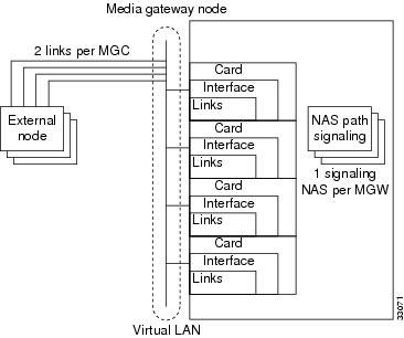
Figure 2-6 shows the order in which the MGW control link components must be configured.

Figure 2-6 Media Gateway Control Link Component Hierarchy

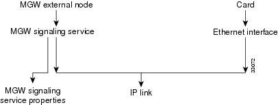
The cards and interfaces shown in Figure 2-5 are configured in the same way as the cards and interfaces used for SS7 signaling links. In fact, you might be able to use the same cards and interfaces previously planned for your MGW control links. You must define IP link components for MGW communications; you cannot use C7 IP links or TDM links.


Tip Links are logical connections between a Cisco MGC physical interface and another device. You can assign multiple links to any interface. When assigning links, be sure to consider fault tolerance. For example, placing all four links between the Cisco MGC and one MGW on the same interface results in a useless MGW if that interface fails.


This section describes how to plan for provisioning the following component types:

1. External nodes

2. Cisco MGC cards

3. Cisco MGC interfaces

4. Media gateway signaling services

5. Override properties (if necessary)

6. IP links


The following sections describe how to plan for each of these components.

Planning Media Gateway External Nodes

An external node is another device, such as a media gateway, with which the Cisco MGC communicates. Within the Cisco MGC software, an external node is a system component that describes another device. The Cisco MGC can connect to a maximum of eight media gateways, and you must configure an external node for each MGW.

To provision media gateway external nodes, you must configure the following component types:

CMM Component Name: ExtNode

MML Component Name: EXTNODE


Note If you are configuring a redundant system, you must define two redundant link manager links between each MGC and MGW. Each redundant link manager group must be associated with a different port number and a different NASPATH, but the same EXTNODE.


Table 2-16 describes the external node configuration parameters, and Table B-14 serves as a form for you to plan a unique name for each media gateway.

Table 2-16 External Node Configuration Parameter Descriptions 

MML Parameter Name
CMM Parameter Name
Default Value
Description

NAME

MML name

None

Unique name for an external device. Enter as many as 10 alphanumeric characters (or 20 alphanumeric characters for Release 7.4) and enclose in straight quotes. Hyphens (-) can be used.

TYPE


None

Identifies the type of external node. (Valid for Release 7.4(8) and later.) Acceptable values are shown in the left column. The right columns show the associated signaling type:

AS3660 SGCP MGCP IPFAS NAS

AS5200 IPFAS NAS

AS5300 SGCP MGCP IPFAS NAS

AS5400 SGCP MGCP IPFAS NAS

AS5800 IPFAS NAS

AS7200 SGCP MGCP IPFAS NAS

CAT8510 SGCP MGCP

CAT8540 SGCP MGCP

LS1010 SGCP MGCP

MGC EISUP

MGX8260 MGCP IPFAS NAS

MGX8850 SGCP MGCP IPFAS

SCP TCAPIP

UNKNOWN UNKNOWN

SIGNALING


None

Identifies the signaling type for the external node. Acceptable values are:

EISUP

MGCP

NAS

SGCP

TCAPIP

COMPONENTID


None

Unique 8-digit identifier for the external node type.

DESC

Description

None

Text description of an external device. Enter as many as 128 characters and enclose in straight quotes.


Planning for the Media Gateway Signaling Service

A media gateway signaling service must be defined for each media gateway. As shown in Table 2-17, each media gateway signaling service defines the parent media gateway external node and assigns a media gateway ID to that device. Table B-16 provides space to plan a single media gateway signaling service.

To provision a media gateway signaling service, you must configure the following component types:

CMM Component Name: SigNAS

MML Component Name: NASPATH

CMM Component Name: SigEISUP

MML Component Name: EISUPPATH

CMM Component Name: SigIPFAS

MML Component Name: IPFASPath

CMM Component Name: TCAPOverIP

MML Component Name: TCAPIPPATH

Table 2-17 Media Gateway Signaling Service Configuration Parameter Descriptions 

MML Parameter Name
CMM Parameter Name
Default Value
Description

NAME

MML name

None

Unique name for this signaling service. Enter as many as 10 alphanumeric characters (or 20 alphanumeric characters for Release 7.4) and enclose in straight quotes. Hyphens (-) can be used.

MDO

MDO file name

None

Enter a valid message definition object (MDO) file protocol name by using the PROV-RTRV:VARIANTS MML command.

EXTNODE

External node

None

Enter the external node name assigned to the media gateway you are configuring.

SIDE

Side

network

Q.931 call model side. Enter user for user side or network for network side.
Default = network. (Used only for IP FAS transport service.)

CUSTGRPID

Customer group ID

0000

Customer Group ID. Virtual network identification characters (formerly called the VNET ID). Values accepted for this field depend on the use of the D channel. Enter the four-digit ID. (Used only for IP FAS transport service.)

CUSTGRP
TBL

Customer group table

NA

Reserved for future use.

ABFLAG

A/B flag

N

A/B flag. Specifies digital private network signaling system (DPNSS) a or b side. Enter A for a side, B for b side, or N for not applicable. (Used only for IP FAS transport service.)

CRLEN

Call reference length

2

Call reference length. Enter 0 for DPNSS, 1 for one-byte call reference, or 2 for two-byte call reference. Default = 2. (Used only for IP FAS transport service.)

DESC

Description

None

Text description of this signaling service. Enter as many as 128 characters and enclose in straight quotes.


Tip When configuring your network, keep in mind that the naming convention and description you use need to uniquely identify and thoroughly describe not only the component but also its source and destination. Even though the name parameter is limited, use a description that will allow someone else to understand the network well enough to scale or troubleshoot it.


Planning Network Cards for Media Gateway Communications

Network cards are the hardware cards installed on the host computer providing the network interfaces that communicate with other devices. When planning media gateway control links, you define the cards that will communicate with the media gateways.


Note In the MGC node system, the same cards and interfaces can be used for communication with Cisco SLTs and media gateways. When configured this way, separate links are assigned for Cisco SLT and media gateway communications.


To provision cards, you must configure the following component types:

CMM Component Name: Adapter

MML Component Name: CARD

Table 2-18 describes configuration parameters you can use to configure network cards, and Table B-1 serves as a form on which you can plan network card configurations.

Table 2-18 Card Configuration Parameter Descriptions for Media Gateway Communications

MML Parameter Name
CMM Parameter Name
Default Value
Description

NAME

MML name

None

Unique name for this component. Enter as many as 10 alphanumeric characters (or 20 alphanumeric characters for Release 7.4) and enclose in straight quotes. Hyphens (-) can be used.

SLOT

Slot

None

Location of card or adapter within the host machine. Acceptable values depend on the host machine. The first slot is usually 0.
Value range: 0 through 15.

TYPE

Type

None

Type of card or adapter. Acceptable values are:

ATM_NIC

EN

ITK

V35

DESC

Description

None

Description of this component. Enter as many as 128 characters and enclose in straight quotes.


Planning Ethernet Interfaces for Media Gateway Communications

Each SS7 link in the MGC node must be associated with an Ethernet interface component, which must be associated with a network card. The Ethernet interface represents a physical network connection on the network card.


Note In the MGC node, the same cards and interfaces can be used for communication with Cisco SLTs and media gateways. When configured this way, separate links are assigned for Cisco SLT and media gateway communications.


To provision an Ethernet interface, you must configure the following component types:

CMM Component Name: EnetIF

MML Component Name: ENETIF

Table 2-19 describes the configuration parameters that define an Ethernet interface. Table B-2 serves as a form for you to plan the Ethernet interfaces on your Cisco MGC.

Table 2-19 Ethernet Interface Configuration Parameter Descriptions

MML Parameter Name
CMM Parameter Name
Default Value
Description

NAME

MML name

None

Unique name for this interface. Enter as many as 10 alphanumeric characters (or 20 alphanumeric characters for Release 7.4) and enclose in straight quotes. Hyphens (-) can be used.

CARD

Ethernet adapter

None

Identifies the card that supports this interface. Set this to the MML name of a card that has already been defined.

DESC

Description

None

Text description of this interface. Enter as many as 128 characters and enclose in straight quotes.


Planning TDM Interfaces for Media Gateway Communications

Each SS7 link in the MGC node must be associated with an interface component, which must be associated with a network card. The interface represents a physical network connection on the network card.


Note In the MGC node, the same cards and interfaces can be used for communication with the Cisco SLTs and media gateways. When configured this way, separate links are assigned for the Cisco SLT and media gateway communications.


To provision a TDM interface for the ITK (T1/E1) or V.35 card, you must configure the following component types:

CMM Component Name: TDMIf

MML Component Name: TDMIF

Table 2-20 lists and describes the configuration parameters that define the TDM interface. Table B-23 serves as a form for you to plan a TDM interface.

Table 2-20 TDM Interface Configuration Parameter Descriptions 

MML Parameter Name
CMM Parameter Name
Default Value
Description

NAME

MML name

None

Unique name for this link. Enter as many as 10 alphanumeric characters (or 20 alphanumeric characters for Release 7.4) and enclose in straight quotes. Hyphens (-) can be used.

CARD

Ethernet adapter

None

Identifies the card that supports this interface. Set this to the MML name of a card that has already been defined.

LIFNUM

Line interface number

None

Selects the line interface number. Choose 1 through 4 for V.35; otherwise, enter 1.

RESIST

Resistance

0

Selects the line resistance. Choose 75 or 120 for an ITK card; otherwise, enter 0.

DATARATE

Data rate

0

Selects the data rate for only the V.35 card. Choose 48, 56, or 64 (kbps).

CLOCK

Clock

INT

Selects the clock source for only the V.35 card. Choose EXT (external) or INT (internal).

DTEDCE

DTE or DCE

DTE

Selects the device type for only the V.35 card. Choose DTE (data terminal equipment) or DCE (data communications equipment).

CODING

Coding

B8ZS

Selects the line coding type on the link. Choose either AMI (alternate mark inversion) or B8ZS (bipolar with 8 zero substitution) for T1. Choose HDB3 (high-density bipolar with 3 zero replacement) for E1. Choose NA (not applicable) for V.35.

FORMAT

Format

ESF

Selects the link framing format. Choose ESF (extended superframe) or D4 (superframe) for T1. Choose CRC4 (cyclic redundancy check 4), CCS (common channel signaling), or NA (not applicable) for V.35.

SIGTYPE

Signal type

T1

Selects the type of signaling on the link. Choose T1 for ANSI (American National Standards Institute) or DS1 (digital signal level 1). Choose CEPT (Conference Europeenne des Postes et des Telecommunications) for E1.
Choose V.35 for 64 kbps digital.

HDLC

Control

HDLC

Selects the HDLC (High-Level Data Link Control) for the ITU link layer protocol standard. Choose IHDLC (Inverted HDLC) for an ITK card; otherwise, choose HDLC.

DESC

Description

None

Text description of this link. Enter as many as 128 characters and enclose in straight quotes.


Planning IP Links

The last step in planning media gateway control links is the planning of the links themselves. You must identify each end of each link as follows:

At the Cisco MGC end of each link, the link is associated with an Ethernet interface, an IP address, and an IP port.

At the media gateway end of each link, the Cisco SLT is identified with an IP address and port.

To provision a media gateway IP link, you must configure the following component types:

CMM Component Name: IPLink

MML Component Name: IPLNK

Table 2-21 lists and describes the configuration parameters that define each link. Table B-9 serves as a form for planning a single IP link.

Table 2-21 IP-Link Configuration Parameter Descriptions 

MML Parameter Name
CMM Parameter Name
Default Value
Description

NAME

MML name

None

Unique name for this link. Enter as many as 10 alphanumeric characters (or 20 alphanumeric characters for Release 7.4) and enclose in straight quotes. Hyphens (-) can be used.

IF

Enet line interface

None

Ethernet interface to which this link connects. Enter the MML name of a previously defined Ethernet interface.

DESC

Description

None

Text description of this link. Enter as many as 128 characters and enclose in straight quotes.

IPADDR

IP address

None

Cisco MGC IP address for interface. Enter the IP address variable defined in the XECfgParm.dat file during the installation of the Cisco MGC. Valid entries ar: IP_Addr1, IP_Addr2, IP_Addr3, or IP_Addr4.

PEERADDR

Peer address

None

Remote IP address of link interface on media gateway.

PEERPORT

Peer port

None

Port number of link interface on remote device.
Enter any valid IP port number greater than 1024. For MGCP and SGCP, 2427 is recommended.

PORT

Port

None

Local port number of link interface on the Cisco MGC. Enter any valid IP port number greater than 1024.

PRI

Priority

1

Priority. Enter an integer that is greater than 0.

SIGPORT

Signal port

0

Physical port on the gateway on the slot.Value range: 0 through 168. (Used only to support IPFAS.)

SIGSLOT

Signal slot

0

Physical slot on the gateway where the T1/E1 is plugged into.
Value range: 0 through 63. (Used only to support IPFAS.)

SVC

IP signaling services

None

Signaling service this IP supports. Enter the MML name of a previously defined signal service.

SIGPORTSKIP


0

Signal port skip. The number of SIGPORT values to be skipped before using the next value. (Used only for NFAS signaling type.)

NEXTHOP

Next hop

0.0.0.0

Router IP address where packets are to be sent for delivery to the PEERADDR that is not a subnet directly connected to the MGC. Typically the PEERADDR is on a subnet directly connected to the MGC. NEXTHOP can be specified in dot notation or using the DNS name. Optional parameter. (Used for Release 7.4(10).) Value range: 0.0.0.0 (default, disables the IP routing feature) through 223.255.255.255.

NETMASK

Net mask

255.255.255.
255

The four-octet value defining the part of the PEERADDR (in dot notation) that is treated as the network address. The upper 28 bits are the network address and the lower 4 bits are the host address. Optional parameter. (Used for Release 7.4(10).) Value range: 128.0.0.0 through 255.255.255.255.


Provisioning Trunk Groups and Trunks

There are two different methods that can be used to provision trunk groups and trunks. Provisioning can be performed individually creating each trunk group and trunk by using MML commands. Or provisioning can be performed by importing a customer-created file.

Provisioning Trunk Groups and Trunks Using MML Commands

Provisioning trunk groups and trunks can be performed using MML commands. Examples of the provisioning MML commands are contained in this chapter. More extensive MML command examples are listed in "Adding System Components with MML."

When provisioning using MML commands, it is important to realize that the MML commands are used to add to existing components. Therefore, MML commands are very useful when modifying existing trunk groups and trunks. However, if you have to create large trunk group or trunk files, importing a file can greatly speed the provisioning effort.

Provisioning Trunk Groups and Trunks Using an Imported File

Importing a customer-created file is another way to provision trunk groups and trunks. The customer file can be created using CMM or a text editor. MML commands cannot be used to create the customer file. After the file is created, you must import it into the Cisco MGC. When importing this file, you can use either MML commands or the CMM.

When provisioning using an imported customer-created file, it is important to realize that the imported file overwrites the existing file. For example, if a customer-created trunk group file is imported, the existing trunk group file is overwritten.

Provisioning a Nailed Configuration

Adding Nailed Trunks

You need to add trunks for each connection between the MGW and a destination switch. These trunks can be either nailed or switched. For nailed trunks, the Cisco MGC does not perform switching of trunks. To create a nailed trunk, you can use an MML command to create a single trunk, use the CMM to create a trunk, or use the MML command to import a trunk file created using a text editor. To add multiple nailed trunks, refer to the "Adding Multiple Nailed Trunks" section.


Note If you have already provisioned the spans on a network access server (NAS) that are to be associated with the trunks being added, remove the spans from service on the NAS using the shutdown command before provisioning trunks on the MGC.


The MML command format used to create one nailed trunk is:

prov-add:nailedtrnk:name="1910",srcsvc="ss7svc1",srctimeslot=101,dstsvc="nassrv1", 
dstspan=3,dsttimeslot=1,spansize=1

Table 2-22 lists the nailed trunk MML command parameter definitions and their associated values.

Table 2-22 Nailed Trunk Parameter Descriptions 

MML Parameter Name
CMM Parameter Name
Description

NAME

Name

Trunk group ID. A numeric identifier for the trunk group. Value range: an integer from 1 through 65535.

SRCSVC

Source service

Used to look up the source service component ID. The MML name of a previously defined signaling service.

SRCSPAN

Source span ID

Corresponds to the source span ID. Value range: an integer from 1 through 65535 or ffff (default). This value is converted from decimal to hexadecimal, except when the value is ffff.

SRCTIMESLOT

Source time slot

Corresponds to the source time slot. Value range: an integer from 0 through 16384. This value is converted from decimal to hexadecimal, except when the value is ffff.

DSTSVC

Destination service name

Used to look up the destination service component ID. The MML name of a previously defined signaling service.

DSTSPAN

Destination span ID

Corresponds to the destination span ID. Value range: an integer from 1 through 65535 or ffff (default). This value is converted from decimal to hexadecimal, except when the value is ffff.

DSTTIMESLOT

Destination time slot

Corresponds to the destination time slot. Value range: an integer from 0 through 16384. This value is converted from decimal to hexadecimal, except when the value is ffff.

SPANSIZE

Span size

Span size. Indicates the number of trunks per span. Value: 1 (default) through 24 for T1, or 1 through 31 for E1.


The MML command format used to import a customer-created nailed trunk file is:

prov-add:files:name="BCFile",file="trunkCust.dat",action="import"

This imports the customer-created file that uses #format2. The imported file format would appear as:

Trunk	Src	Src	Src	Dest	Dest	Dest     
ID	cmp-id	Span	Time slot	cmp-id	Span	Time slot

101	00130002	ffff   65		00140001   3      1
102	00130002	ffff   66   		00140001   3      2

The #format2 fields are Trunk ID, Source Service CompId, Source Span, Source Time slot, Destination Service CompId, Destination Span, and Destination Time slot.

Creating the Trunk Group

Before switched trunk groups and trunks can be created, the following two files need to be created:

Trunk group file—Used to define the trunk group and the signal path controlling the trunk group

Trunk file—Used to define the trunks (also called bearer channels) associated with a trunk group. The trunk file is a switched trunk.

This imports the customer-created bearer channel switched file using #format3.

Once these files are created, you can use the MML command to import a trunk group file created using a text editor. Create the trunk group file and bearer channel file using a text editor and then importing the files.

You can either use the MML commands, listed above, to import a trunk group file, or you can use the following MML command to populate a trunk group one line at a time.

Populating a Trunk Group File

After you create a trunk group file, you need to populate that file. Trunk group information is used to populate the trunkGroup file and spawns information for the Properties file and the SigPath file.

The MML command format used to create a trunk group row in the trunk group file is:

prov-add:trnkgrp:name="1910",clli="tg1910",svc="bh-path-33",type="TDM_PRI", 
selseq="ASC",qable="N"

Table 2-23 lists the trunk group parameter definitions and their associated values.

Table 2-23 Trunk Group Parameter Descriptions 

MML Parameter Name
CMM Parameter Name
Description

NAME

Name

Trunk group ID. A numeric identifier for the trunk group. An integer from 1 through 65535.

CLLI

CLLI

Common language location identifier that identifies the trunk group.

SVC

Signal service

The MML name of the signaling service associated with or controlling the trunk group.

TYPE

Type

Identifies the trunk group type. Value range: 0 through 8.

0 = TDM_GEN—Used with SS7 signaling services with switch types not equal to 0, 5, or 20.
1 = TDM_ISUP (default)—Used with SS7 signaling services with switch types of 0 or 20.
2 = TDM_CAS—Currently not supported.
3 = TDM_TUP—Used with SS7 signaling services with switch type of 5.
4 = IP—Used with EISUP signaling service.
5 = ATM—Used with VSI path signaling service.
6 = TDM_DPNSS—Used with DPNSS protocol family signaling services
7 =TDM_ PRI—Used with ISDN PRI protocol family signaling services.
8 = TDM_BTNUP—Used with SS7 signaling services with switch type of 5.

SELSEQ

Selection sequence

Determines the trunk selection sequence. It is used to eliminate or reduce the chance of glare when selecting a trunk. Values:

ASC = Ascending (default)
DESC = Descending
EASC = Even ascending, then odd ascending
EDECS = Even descending, then odd descending
LIDL = Least idle
MIDL = Most idle
OASC = Odd ascending, then even ascending
ODESC = Odd descending, then even descending
RDM = Random

QABLE

Queuable

Determines if queuing is used on the trunk during call processing. Value range: Y for yes or N for no (default).


In addition to the trunk group parameters listed in Table 2-23, additional properties can be set or changed in the text file. To add multiple trunk groups, refer to the "Adding Multiple Trunk Groups and Bearer Channels" section. Table 2-24 lists the trunk group property MML parameter definitions and their associated values.

Table 2-24 Trunk Group File Properties Descriptions 

MML Parameter Name
CMM Parameter Name
Description

RingNoAnswer

RNA

Ring no answer. Indicates the time, in seconds, ringing is allowed to occur. Value range: 0 through 255, which is converted to milliseconds.

GLARE

Glare control

Glare control. Glare is a collision that occurs when two network nodes simultaneously attempt to reserve the same channel. Values are: 1 (always), 2 (even/odd), or 3 (never) (default).

CotPercentage

Cot percentage

Determines the percentage of calls on the trunk upon which a continuity test is performed. Value range: 0 through 100.

VSF

VSF priority

Virtual switch fabric priority. Determines if the gateway attempts to find a trunk on the same gateway as the incoming trunk or on any available trunk. Values are 0 (no) (default) or 1 (yes).

SatelliteInd

Satellite

Satellite indicator. Indicates if the trunk is going over a satellite. Values are 0 (no) (default) or 1 (yes).

Npa

Npa

Numbering plan area. Indicates the NPA code associated with the incoming trunk group. Value range: 0 (none) (default), or 200 through 999.

CarrierIdentity


Carrier identity. Indicates the carrier ID to which users on this trunk group are associated. Value range: 0 (if not defined) or 1 through 9999.

ScreenFailAction


Screen fail action. Indicates if an action is to be performed when a screening failure occurs. Values are 0 (no action) (default) or 1 rejectCall.

CustGrpId


Customer group ID. The ID of the customer associated with this trunk group. Value range: 0 (if not defined) or any 4-character alphanumeric string.

BOrigStartIndex


B originating start index. Identifies the entry point into the originating side of the dial plan. Values are 0 (no dial plan) or 1 (for the first node in the originating digit tree).

BTermStartIndex


B terminating start index. Identifies the entry point into the terminating side of the dial plan. Values are 0 (no dial plan) or 2 (for the first node in the terminating digit tree).

CompressionType


Compression type. Identifies the G.711 compression type used on the trunk. After the fax or modem tone has been detected by the MGW, select the proper compression type. Values are 0 (none), 1 (mu-law) (default), or 2 (A-law).

EchoCanRequired


Echo cancellation. Indicates if echo cancellation is required. Values are 0 (no echo cancellor required) (default) or 1 (dynamic echo cancellor required). (Valid for Release 7.4 only.)

ExtCOT


External COT. Identifies the type of COT handling for the specified destination. Values: 0 (no COT), Loop (default), or Transponder. (Valid for Release 7.4.7(8) only.)

Note This value is case sensitive.


DetectFaxModem
Tone


Detect Fax Modem Tone. Used for MGCP connection protocol. Values are 0 (no tone detection notification) (default) or 1 (request fax or modem tone detection from the MGW.

CompressionType


Compression type. Identifies the G.711 compression type used on the trunk. After the fax or modem tone has been detected by the MGW, select the proper compression type. Values are: 0 (none), 1 (mu-law) (default), or 2 (A-law).

DetectFaxModem
Tone


Detect Fax Modem Tone. Used for MGCP connection protocol. Values are 0 (no tone detection notification) (default) or 1 (request fax or modem tone detection from the MGW.

ACCRespCntlInhibit


Automatic congestion control response inhibit. Enables or disables the ACC control procedures based on the ACL value received by MGC from a linked switch. Values are: 0 (default) or 1.

ACLDuration


Automatic congestion level duration. When MGC receives ACL indication from a linked switch, the MGC assumes ACL is in effect for the duration specified (in seconds). Value range: Any value greater than 0 (5 is the default).

AOCEnabled


Advice of charge (AOC). Determines whether or not AOC handling is applied to the current call. Values are: 0 (AOC not enabled) (default) or 1 (AOC enabled).

CarrierScreening


Carrier screening. Defines whether or not carrier screening and selection is to be applied on the current call (using the Carrier Translation table). Values are: 0 (do not apply screening) (default), or 1 (do apply screening).

IsupTransparencyDisabled


ISUP transparency disable function. Permits disabling the ISUP transparency feature for a specified trunk group. Values are: 0 (ISUP transparency enabled) (default), or 1 (ISUP transparency disabled).

MaxACL


Maximum automatic congestion level. The MGC indicates its congestion level (if it is greater than 0) in the ISUP release message. Values: 0, 2, or 3 (default).

OrigCarrierId


Originating carrier ID. Supports the Carrier Screening capability as handled in the protocol. This property supplies the CarrierID digit string for the trunk group that can be referenced to any CarrierID received in the incoming message. Value range is 0 through 99999 (00 is the default).


After you have populated the trunk group file, if you want to change any properties in that file, make the property changes using the text editor. Then use the MML add command to add the trunk group file and the bearer channel file, even though you have not made any changes to the bearer channel file.

The following is an example of a trunk group file #format3 text format:

#format3
1910 TG1910 bh-path-33  TDM_PRI  N 180 2 100 ASC 0 0 501 0333 0 cujo 1 0 1 1
2744 TG2744 ss7-135033  TDM_ISUP N 180 2 0   ASC 0 0 502 0333 0 cujo 1 0 1 1
3913 TG3913 bh-pth-332  TDM_PRI  N 180 2 100 ASC 0 0 503 0333 0 cujo 1 0 1 1
4714 TG4714 ss7-135033  TDM_ISUP N 180 2 0   ASC 0 0 504 0333 0 cujo 1 0 1 1
1910 TG1910 bh-path-34  TDM_PRI  N 180 2 0   ASC 0 0 511 0333 0 cujo 1 0 1 1

Populating a Trunk File

After you have finished creating a trunk file, you need to populate that file. Trunk information is used to populate the trunk file. Create a trunk row entry in the trunk file using a text editor. Then use the MML command to import the trunk file (trunkCust.txt).

Table 2-25 lists the trunk MML parameter definitions and their associated values.

Table 2-25 Trunk Parameter Descriptions 

MML Parameter Name
CMM Parameter Name
Description

NAME

Trunk group member number

Identifies the trunk group member number. A numeric identifier for the trunk group member. An integer from 1 through 65535.

TRNKGRPNUM

Trunk group number

Identifies the trunk group number. Value range: an integer from 1 through 65535. Not used for ISDN.

SPAN

Span ID

Identifies the span. Value range: an integer from 1 through 65535 or ffff. (Not required for TDM.)

CIC

Circuit identifier code

Identifies the trunk time slot or circuit identification code. Value range: an integer from 1 through 65535.

CU

Coding unit

Identifies the coding unit MML name that was previously defined for the VISM card (this is the external node created for MGCP or SGCP).

ENDPOINT

End point

Text description of the trunk end point (typically a VISM card). Enter as many as 128 characters and enclose in straight quotes.

SPANSIZE

Span size

Span size. Indicates the number of trunks per span.
Value range: 1 through 24 for T1, or 1 through 31 for E1.


The following is an example of a trunk file text format:

#format3
1910 191001 0 1 as5300-33 S0/DS1-0/1@as5300-33
1910 191002 0 2 as5300-33 S0/DS1-0/2@as5300-33
1910 191003 0 3 as5300-33 S0/DS1-0/3@as5300-33
1910 191004 0 4 as5300-33 S0/DS1-0/4@as5300-33
1910 191005 0 5 as5300-33 S0/DS1-0/5@as5300-33

Route Analysis

Routing analysis is necessary for you to identify the path for bearer traffic from the Cisco MGC to the adjacent switch.

Creating a Routing Trunk Group

You need to create a routing trunk group. You can use either the MML command to create a routing trunk group or use the CMM to import a routing file.

Provisioning a Routing Trunk Group Using MML Commands

Provisioning routing trunk groups can be performed using MML commands. Examples of the provisioning MML commands are contained in this chapter. More extensive MML command examples are listed in "Adding System Components with MML."

When provisioning using MML commands, it is important to realize that the MML commands are used to add to existing components. Therefore, MML commands are very useful when modifying existing a routing trunk groups. However, if you have to create large routing trunk group, importing a file can greatly speed the provisioning effort.

The MML command format used to create a row in the routing trunk group file is:

prov-add:rttrnkgrp:name="1910",type=7,reattempts=1,queuing=0,cutthrough=2

Table 2-26 lists the routing trunk group MML command parameter definitions and their associated values.

Table 2-26 Routing Trunk Group Parameter Descriptions

MML Parameter Name
CMM Parameter Name
Description

NAME

Name

Unique name for this routing trunk group number. Enter as many as 10 alphanumeric characters (or 20 alphanumeric characters for Release 7.4) and enclose in straight quotes. Hyphens (-) can be used.

TYPE

Type

Identifies the trunk group type. Value range: 0 through 8.

0 = TDM_GEN—Used with SS7 signaling services with switch types not equal to 0, 5, or 20.
1 = TDM_ISUP (default)—Used with SS7 signaling services with switch types of 0 or 20.
2 = TDM_CAS—Currently not supported.
3 = TDM_TUP—Used with SS7 signaling services with switch type of 5.
4 = IP—Used with EISUP signaling service.
5 = ATM—Used with VSI path signaling service
6 = TDM_DPNSS—Used with DPNSS protocol family signaling services
7 =TDM_ PRI—Used with ISDN PRI protocol family signaling services.
8 = TDM_BTNUP—Used with SS7 signaling services with switch type of 5.

REATTEMPTS

Reattempts

Identifies the number of times the system reattempts to select a trunk group.
Value range: 0 (default) through 65535.

QUEUING

Queuing

Identifies the duration (in seconds) the call will be queued.
Value range: 0 (default) through 65535.

CUTTHROUGH

Cutthrough

Identifies the point in the call process where the trunk is seized from end point to end point. Value range: 0 (default) through 3.

1 - Seize
2 - ACM
3 - Answer
It defaults to 0 if cutthrough is not defined.


Provisioning a Routing Trunk Group Using an Imported File

Importing a customer-created file is another way to provision routing trunk groups. The customer file can be created using CMM or a text editor. MML commands cannot be used to create the customer file. After the file is created, you must import it into the Cisco MGC. When importing this file, you can use either MML commands or the CMM.

When you are provisioning using an imported customer-created file, it is important to realize that the imported file overwrites the existing file. For example, if a customer-created routing trunk group file is imported, the existing routing trunk group file is overwritten.

After the routing trunk group file has been created, you need to associate a route with a trunk group.

Associating a Route with a Trunk Group

You need to create a route to connect to a trunk group. You can use either the MML commands to associate a route with a trunk group or use the CMM to import a routing file.

The MML command format used to create a row in the route trunk file is:

prov-add:rttrnk:name="rt1910",trnkgrpnum=501910

Table 2-27 lists the route trunk MML command parameter definitions.

Table 2-27 Route Trunk Parameter Descriptions

MML Parameter Name
CMM Parameter Name
Description

NAME

Name

Unique name for this routing trunk group. Enter as many as 10 alphanumeric characters (or 20 alphanumeric characters for Release 7.4) and enclose in straight quotes. Hyphens (-) can be used.

TRNKGRPNUM

Trunk group number

Identifies the trunk group number.

NEXTNAME

Next route

Identifies the next route name.


Each line entry in the route trunk file is one entry in the route list file.

Creating a Route List

After you have finished creating a route trunk, you need to create a route list. You can use either the MML command to create a route list, use the CMM, or import a routing file.

The MML command format used to create the route list is:

prov-add:rtlist:name="rtlist1910",rtname="rt1910",carrierid=333

Table 2-28 lists the route list MML command parameter definitions and their associated values.

Table 2-28 Route List Parameter Descriptions 

MML Parameter Name
CMM Parameter Name
Description

LISTINDEX

List index

Indicates the index value. (Not used in Release 7.4.)

NAME

Name

Unique name for this route trunk. Enter as many as 10 alphanumeric characters (or 20 alphanumeric characters for Release 7.4) and enclose in straight quotes. Hyphens (-) can be used.

RTNAME

Route name

Used to look up the source service component ID.

CARRIERID

Carrier ID

Carrier identity. Indicates the carrier ID. The carrier ID must be the same for each route in the route list. Value range: 0 (if not defined) or 1 through 9999.

NEXTRTNAME


Next route name.


Note What is called a route list in MML is called a route group in CMM.


An MML Example for Creating a Routing File

The following MML commands provide a sample routing file:

prov-add:rttrnkgrp:name="1910",type=7,reattempts=1,queuing=0,cutthrough=2
prov-add:rttrnkgrp:name="2744",type=1,reattempts=1,queuing=0,cutthrough=2
prov-add:rttrnkgrp:name="3913",type=7,reattempts=1,queuing=0,cutthrough=2
prov-add:rttrnkgrp:name="3914",type=1,reattempts=1,queuing=0,cutthrough=2
prov-add:rttrnk:name="rt1910",trnkgrpnum=1910
prov-add:rttrnk:name="rt2744",trnkgrpnum=2744
prov-add:rttrnk:name="rt3913",trnkgrpnum=3913
prov-add:rttrnk:name="rt3914",trnkgrpnum=3914
prov-add:rtlist:name="rtlist1910",rtname="rt1910",carrierid=333
prov-add:rtlist:name="rtlist2744",rtname="rt2744",carrierid=333
prov-add:rtlist:name="rtlist3913",rtname="rt3913",carrierid=333
prov-add:rtlist:name="rtlist3914",rtname="rt3914",carrierid=333