Feedback
Table Of Contents
Setting Up the Cisco Unified Wireless IP Phone 7921G
Methods for Adding Phones to Cisco Unified Communications Manager
Adding Phones with Auto-Registration
Adding Phones with Auto-Registration and TAPS
Adding Phones with Cisco Unified Communications Manager Administration
Installing the Cisco Unified Wireless IP Phone 7921G
Installing or Removing the Phone Battery
Using the Power Supply to Charge the Phone
Using the USB Cable to Charge the Phone
Installing and Using the Desktop Charger
Using the Desktop Charger to Charge the Phone
Battery Charging Times Using the Desktop Charger
Configuring Wireless LAN Settings for the Cisco Unified Wireless IP Phone 7921G
Cisco Unified Wireless IP Phone 7921G Web Pages
Network Profile Menu on the Cisco Unified Wireless IP Phone 7921G
Audio Quality Subjective to the User
Using External Devices with Your Cisco Unified IP Phone
Powering On the Cisco Unified Wireless IP Phone 7921G
Active and Standby Phone Modes
Understanding the Phone Startup Process
Setting Up the Cisco Unified Wireless IP Phone 7921G
This chapter includes the following topics, which help you install and configure the Cisco Unified Wireless IP Phone 7921G on an IP telephony network:
•
Installing the Cisco Unified Wireless IP Phone 7921G
•
Before You Begin
Before installing a Cisco Unified Wireless IP Phone 7921G, review the requirements in these sections:
•
Network Requirements
For the Cisco Unified Wireless IP Phone 7921G to successfully operate as a Cisco Unified IP Phone endpoint, your network must support these requirements:
Voice-over-Wireless Network (VoWLAN)
•
•
•
Note
Voice-over-IP (VoIP) Network
•
•
–
–
•
Related Topics
•
•
•
•
•
Methods for Adding Phones to Cisco Unified Communications Manager
Before installing the wireless IP phone, you must choose a method for adding phones to the Cisco Unified Communications Manager database. Some methods require entering the media access control (MAC) address of the phone. Table 3-1 provides an overview of these methods.
The following sections describe these methods:
•
•
•
Adding Phones with Auto-Registration
You can use auto-registration to quickly enter phones into the Cisco Unified Communications Manager database without first gathering MAC addresses from the phones.
When auto-registration is enabled, Cisco Unified Communications Manager automatically assigns the next available sequential directory number to new phones as they register with Cisco Unified Communications Manager during the initial phone startup process.
After registering phones with Cisco Unified Communications Manager, you can modify settings, such as the directory numbers and device pools, by using Cisco Unified Communications Manager Administration.
Auto-registration is disabled by default in Cisco Unified Communications Manager. You must enable and properly configure auto-registration before connecting any Cisco Unified IP Phone to the network. For information about enabling and configuring auto-registration, refer to Cisco Unified Communications Manager Administration Guide.
Related Topics
•
•
Adding Phones with Auto-Registration and TAPS
You can add a group of phones quickly by using auto-registration and TAPS. First, use the Bulk Administration Tool (BAT) to add phones to the Cisco Unified Communications Manager database with dummy MAC addresses. Then use TAPS to update MAC addresses and download pre-defined configurations for the phones.
To implement TAPS, you or the end-users dial a TAPS directory number and follow voice prompts. When the process is complete, the phone has downloaded its directory number and other settings. The correct MAC address for the phone is updated in Cisco Unified Communications Manager Administration.
You must enable auto-registration in Cisco Unified Communications Manager Administration for TAPS to function.
Refer to Bulk Administration Tool User Guide for Cisco Unified Communications Manager for detailed instructions about BAT and about TAPS.
Related Topics
•
•
Adding Phones with BAT
To add a group of phones to the Cisco Unified Communications Manager database, you can use BAT. This application enables you to perform batch operations, including registration, on multiple phones.
BAT is included in Cisco Unified Communications Manager 5.0 or later, but it is a plug-in for prior releases such as 4.x.
To add phones using BAT only (not in conjunction with TAPS), you first must obtain the appropriate MAC address for each phone.
Determining the MAC Address of a Cisco Unified IP Phone
When adding phones to the Cisco Unified Communications Manager database using Cisco Unified Communications Manager Administration or using BAT, you must enter the media access control (MAC) address of the phone. Table 3-2 describes how to determine the MAC address of the wireless IP phone.
For detailed instructions about using BAT, refer to the Cisco Unified Communications Manager Bulk Administration Guide (for Cisco Unified Communications Manager 5.0 or later) and Cisco Unified Communications Manager Administration Guide (for releases prior to Cisco Unified Communications Manager 5.0)
Note
Related Topics
•
•
•
Adding Phones with Cisco Unified Communications Manager Administration
You can add phones individually to the Cisco Unified Communications Manager database using Cisco Unified Communications Manager Administration. To do so, you first must obtain the MAC address for each phone. See the "Methods for Adding Phones to Cisco Unified Communications Manager" section for instructions.
After you have collected MAC addresses, do one of the following in Cisco Unified Communications Manager Administration to begin:
•
•
For additional instructions and conceptual information about Cisco Unified Communications Manager, refer to Cisco Unified Communications Manager Administration Guide and to Cisco Unified Communications Manager System Guide.
Related Topics
•
•
Safety Information
Review the following warnings before installing the Cisco Unified IP Phone. To see translations of these warnings, refer to the Regulatory Compliance and Safety Information for the Cisco Unified Wireless IP Phone 7921G and Peripheral Devices document that accompanied this device.
Warning
Warning
Warning
Warning
Warning
Warning
Warning
Warning
Warning
Battery Safety Notices
These battery safety notices apply to the batteries that are approved by the Cisco Unified Wireless IP Phone 7921G manufacturer.
Warning
Warning
Caution
Caution
Caution
Caution
Caution
Caution
Caution
Caution
Standard battery—CP-BATT-7921G-STD
Extended battery—CP-BATT-7921G-EXT
Caution
Australia—CP-PWR-7921G-AU
Central Europe—CP-PWR-7921G-CE
China—CP-PWR-7921G-CN
Japan—CP-PWR-7921G-JP
North America—CP-PWR-7921G-NA
United Kingdom—CP-PWR-7921G-UK
Note
Related Topics
Installing the Cisco Unified Wireless IP Phone 7921G
After setting up the wireless network to support voice communications and configuring the wireless IP phones in Cisco Unified Communications Manager, you are ready to install the phones. This section includes the following installation information:
•
Providing Power to the Phone
The Cisco Unified Wireless IP Phone 7921G uses a battery for power. Table 3-3 lists the types of batteries available for the wireless IP phone and the maximum talk and standby times.
Table 3-4 shows the charging time for the two types of batteries. You can stop charging the battery when the battery is fully charged, and leave the batteries in the charger with no ill effects. Lithium ion batteries can be partially charged without shortening the battery life. Batteries should handle up to 4000 recharges.
The following sections provide information about the battery and charging the phone:
•
•
•
•
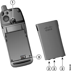
Installing or Removing the Phone Battery
To install the battery in the Cisco Unified Wireless IP Phone use Figure 3-1, and follow these steps:
Procedure
Step 1
Step 2
Step 3
Figure 3-1 Cisco Unified Wireless IP Phone 7921G Battery Installation
Note
Using the Power Supply to Charge the Phone
To charge the battery in your phone quickly, you can use the power supply. You must assemble the appropriate AC adapter plug and then connect the power supply.
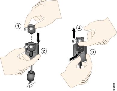
Assembling or Removing the AC Plug Adapter
To assemble or remove the AC plug adapter for the power supply, use Figure 3-1, and follow these steps:
Procedure
Step 1
Step 2
Step 3
Step 4
Figure 3-2 Assembling and Removing the AC Plug Adapter
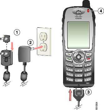
Charging the Phone Using the Power Supply
After assembling the power supply, you are ready to charge your Cisco Unified Wireless IP Phone 7921G. You can use the phone while the battery is being charged. For charging times, see Table 3-5.
To charge the Lithium ion battery using the power supply, follow these steps:
Procedure
Step 1
Step 2
Step 3
Step 4
Figure 3-3 Charging the Phone Using the Power Supply
AC plug adapter
AC power supply
Phone connector on AC power supply cable
Indicator light (LED)
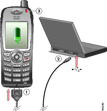
Using the USB Cable to Charge the Phone
You can charge the phone by using a USB cable connected to a USB port on you PC. Charging times are longer when you use the USB cable. See Table 3-4 for charging times.
Figure 3-4 Charging the Phone Using a USB Cable Connected to a PC
Phone connection—Insert into slot at bottom of phone.
USB connector—Insert into USB port on PC.
Indicator LED—Indicates the charging status.
Note
To turn off the Found New Hardware Wizard when using the USB cable to charge the phone, follow these steps:
Procedure
Step 1
Step 2
The Found New Hardware Wizard dialog opens.
Step 3
Step 4
Step 5
Step 6
The phone briefly displays "USB Connected" on the status line.
While the battery is charging, the indicator light is red.
Step 7
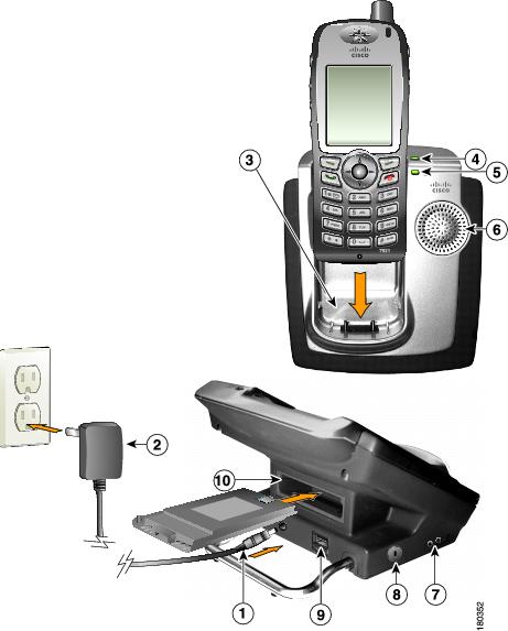
Installing and Using the Desktop Charger
The desktop charger can charge both the phone battery installed in the phone and a spare battery at the same time.You can place the phone in the desktop charger to use the speakerphone capability while charging the phone and battery. For information about using the desktop charger speakerphone, refer to the "Using a Handset, Headset, and Speakerphone" in the Cisco Unified Wireless IP Phone 7921G Guide.
To identify the desktop charger components and how to set up the desktop charger, use Figure 3-5.
Figure 3-5 Desktop Charger Assembly and Components
Using the Desktop Charger to Charge the Phone
To use the desktop charger to charge the phone and spare battery, follow these steps:
Procedure
Step 1
Step 2
Step 3
Note
Step 4
Table 3-5 gives the battery charging time information.
Battery Charging Times Using the Desktop Charger
The LED indicator on the phone turns green and the phone beeps when the phone battery is charged. The battery LED indicator on the desktop charger turns green when the spare battery is charged. Batteries will stop charging after they are fully charged. You can leave the phone or battery in the charger for extended periods of time with no problems.
Table 3-5 lists the approximate battery charging times when using the desktop charger.
Related Topics
•
•
•
Configuring Wireless LAN Settings for the Cisco Unified Wireless IP Phone 7921G
Before the phone can connect to the WLAN, you must configure the network profile for the phone with the WLAN settings. You can use two methods for setting up the network profiles:
•
•
Cisco Unified Wireless IP Phone 7921G Web Pages
You can access the Cisco Unified Wireless IP Phone 7921G web pages to set up the WLAN settings in the network profile. For a new phone with the factory default settings, you must use the USB cable to connect the phone to your PC. For more information and instructions, see Chapter 4, "Using the Cisco Unified Wireless IP Phone 7921G Web Pages."
Network Profile Menu on the Cisco Unified Wireless IP Phone 7921G
You can use the Settings menu on the phone and access the Network Profiles menu to set up the network configuration and the WLAN configuration. For more information and instructions, see Chapter 5, "Configuring Settings on the Cisco Unified Wireless IP Phone."
Using a Headset
Although Cisco Systems performs some internal testing of third-party headsets for use with the Cisco Unified IP Phones, Cisco does not certify or support products from headset or handset vendors. Because of the inherent environmental and hardware inconsistencies in the locations where Cisco Unified IP Phones are deployed, there is not a single "best" solution that is optimal for all environments. Cisco recommends that customers test the headsets that work best in their environment before deploying a large number of units in their network.
In some instances, the mechanics or electronics of various headsets can cause remote parties to hear an echo of their own voice when they speak to Cisco Unified IP Phone users.
Cisco Systems recommends the use of good quality external devices, like headsets that are screened against unwanted radio frequency (RF) and audio frequency (AF) signals. Depending on the quality of these devices and their proximity to other devices such as cell phones and two-way radios, some audio noise may still occur. See the "Using External Devices with Your Cisco Unified IP Phone" section for more information.
The primary reason that support of a headset would be inappropriate for an installation is the potential for an audible hum. This hum can either be heard by the remote party or by both the remote party and the Cisco Unified IP Phone user. Some potential humming or buzzing sounds can be caused by a range of outside sources, for example, electric lights, being near electric motors, large PC monitors. See the "Safety Information" section for more information.
Audio Quality Subjective to the User
Beyond the physical, mechanical and technical performance, the audio portion of a headset must sound good to the user and the party on the far end. Sound is subjective and Cisco cannot guarantee the performance of any headsets or handsets, but some of the headsets and handsets on the sites listed below have been reported to perform well on Cisco Unified IP Phones.
Nevertheless, it is ultimately still the customer's responsibility to test this equipment in their own environment to determine suitable performance. For information about headsets, see:
Connecting a Headset
To connect a headset to the Cisco Unified Wireless IP Phone 7921G, plug it into the headset port on the right side of the phone.
You can use the headset with all of the features on the Cisco Unified Wireless IP Phone 7921G, including the Volume and Mute buttons. Use these buttons to adjust the ear piece volume and to mute the speech path from the headset microphone.
Using External Devices with Your Cisco Unified IP Phone
The following information applies when you use external devices with the Cisco Unified IP Phone:
Cisco recommends the use of good quality external devices (speakers, microphones, and headsets) that are shielded (screened) against unwanted radio frequency (RF) and audio frequency (AF) signals.
Depending on the quality of these devices and their proximity to other devices such as mobile phones or two-way radios, some audio noise may still occur. In these cases, Cisco recommends that you take one or more of the following actions:
•
•
•
•
•
Cisco cannot guarantee the performance of the system because Cisco has no control over the quality of external devices, cables, and connectors. The system will perform adequately when suitable devices are attached using good quality cables and connectors.
Caution
Powering On the Cisco Unified Wireless IP Phone 7921G
After charging the battery and configuring the wireless IP phone, you are ready to power on the phone and connect to the WLAN. Use the following sections for more information about starting up the phone:
•
•
To power on the Cisco Unified Wireless IP Phone 7921G, press and hold the Power On button until the phone begins its startup process by cycling through these steps:
1.
2.
•
•
•
•
•
3.
•
•
•
•
•
When the phone passes through these stages with no errors, the phone started up properly. Now the phone is in standby mode and is ready to place or receive calls.
The signal icon in the upper left corner shows the strength of the signal between the wireless access point and the phone. The phone must have an adequate signal to successfully place or receive calls. If the signal icon displays only one bar, the weak signal can cause problems with phone performance.
Note
If the phone does not complete these steps successfully, see the "Resolving Startup and Connectivity Problems" section on page 10-1.
Related Topics
•
•
Active and Standby Phone Modes
When the Cisco Unified Wireless IP Phone 7921G is powered on, it can be in one of these two modes:
•
•
Active mode
The phone is in active mode when there is an active RTP stream. When the phone is performing one of these actions, it is consuming power:
•
•
•
•
•
The standard battery provides up to 10 hours of talk time in active mode and the extended battery provides up to 12 hours of talk time.
Standby mode
The phone goes into standby mode two seconds after a scan is complete.
The phone will awake from standby mode in response to these events:
•
•
•
•
•
•
The standard battery provides up to 80 hours of standby time and the extended battery provides up to 100 hours of standby time.
Related Topics
•
•
Understanding the Phone Startup Process
When connecting to the wireless VoIP network, the Cisco Unified Wireless IP Phone 7921G goes through a standard startup process, as described in Table 3-6. Depending on your specific network configuration, not all of these steps may occur on your unified IP phone.
Table 3-6 Cisco Unified Wireless IP Phone Startup Process
1. Powering on the phone
The Cisco Unified Wireless IP Phone 7921G has non-volatile Flash memory in which it stores firmware images and user-defined preferences. At startup, the phone runs a bootstrap loader that loads a phone image stored in Flash memory. Using this image, the phone initializes its software and hardware.
2. Scanning for an access point
The Cisco Unified Wireless IP Phone 7921G scans the RF coverage area with its radio. The phone searches its network profiles and scans for access points that have a matching SSID and authentication type. The phone associates with the access point with the highest RSSI that matches with its network profile.
Interacting with Cisco Unified Wireless Access Points, page 2-12
3. Authenticating with access point
The Cisco Unified Wireless IP Phone 7921G begins the authenticating process.
•
•
•
•
–
–
Authentication Mechanisms in the Wireless Network, page 2-19
4. Configuring IP network
If the unified IP phone is using DHCP to obtain an IP address, the phone queries the DHCP server to obtain one. If you are not using DHCP in your network, you must assign a static IP address to each phone locally.
In addition to assigning an IP address, the DHCP server directs the unified IP phone to a TFTP server. If the phone has a statically defined IP address, you must configure the TFTP server IP address locally on the phone; the phone then contacts the TFTP server directly.
•
5. Downloading Load ID
The unified IP phone checks to verify that the proper firmware is installed or if new firmware is available to download.
Cisco Unified Communications Manager informs devices using.cnf or .cnf.xml format configuration files of their load ID. Devices using .xml format configuration files receive the load ID in the configuration file.
6. Downloading config file
The TFTP server has configuration files and profile files. A configuration file includes parameters for connecting to Cisco Unified Communications Manager and information about which image load a phone should be running. A profile file contains various parameters and values for phone and network settings.
•
•
7. Connecting to Cisco Unified
Communications ManagerThe configuration file defines how the Cisco Unified IP Phone communicates with Cisco Unified Communications Manager. After obtaining the file from the TFTP server, the phone attempts to make a TCP connection to the highest priority Cisco Unified Communications Manager on the list.
•
8. Registering to Cisco Unified Communications Manager
If the phone was manually added to the database, Cisco Unified Communications Manager identifies and registers the phone. If the phone was not manually added to the database and auto-registration is enabled in Cisco Unified Communications Manager, the phone attempts to auto-register itself in the Cisco Unified Communications Manager database.
•
Related Topics
•
•