-
Cisco Unified Communications SRND Based on Cisco Unified Communications Manager 6.x
-
Preface
-
Introduction
-
Unified Communications Deployment Models
-
Network Infrastructure
-
Gateways
-
Cisco Unified CM Trunks
-
Media Resources
-
Music on Hold
-
Call Processing
-
Call Admission Control
-
Dial Plan
-
Emergency Services
-
Third-Party Voicemail Design
-
Cisco Unity
-
Cisco Unity Express
-
Cisco Unified MeetingPlace Integration
-
Cisco Unified MeetingPlace Express
-
IP Video Telephony
-
LDAP Directory Integration
-
Migrating to a Unified Communications System
-
Voice Security
-
Unified Communications Endpoints
-
Device Mobility
-
Cisco Unified Presence
-
Cisco Unified CM Applications
-
Cisco Mobility Applications
-
Network Management
-
Cisco Unified Communications Manager Business Edition
-
Recommended Hardware and Software Combinations
-
Glossary
-
Index
-
Table Of Contents
Unified Communications Deployment Models
Benefits of the Single-Site Model
Best Practices for the Single-Site Model
Multisite WAN with Centralized Call Processing
Best Practices for the Centralized Call Processing Model
Voice Over the PSTN as a Variant of Centralized Call Processing
Multisite WAN with Distributed Call Processing
Benefits of the Distributed Call Processing Model
Best Practices for the Distributed Call Processing Model
Call Processing Agents for the Distributed Call Processing Model
Call Detail Records (CDR) and Call Management Records (CMR)
Local Failover Deployment Model
Unified CM Provisioning for Local Failover
Music on Hold and Media Resources for Local Failover
Remote Failover Deployment Model
Design Considerations for Section 508 Conformance
Unified Communications Deployment Models
Last revised on: September 30, 2008
This chapter describes the deployment models for Cisco Unified Communications Manager (Unified CM) 6.x. For design guidance with earlier releases of Cisco Unified CM, refer to the Unified Communications Solution Reference Network Design (SRND) documentation available at
Each Cisco Unified Communications solution is based on a Unified CM deployment model, and the type of deployment model is based on one or more of the following factors:
•
Number of call processing agent clusters
•
•
The following sections describe the various types of deployment models:
•
•
What's New in This Chapter
Table 2-1 lists the topics that are new in this chapter or that have changed significantly from previous releases of this document.
Single Site
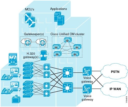
The single-site model for Cisco Unified Communications consists of a call processing agent cluster located at a single site, or campus, with no telephony services provided over an IP WAN. An enterprise would typically deploy the single-site model over a LAN or metropolitan area network (MAN), which carries the voice traffic within the site. In this model, calls beyond the LAN or MAN use the public switched telephone network (PSTN).
The single-site model has the following design characteristics:
•
•
•
•
•
•
•
•
•
•
•
•
Figure 2-1 illustrates the model for a Cisco Unified Communications network within a single campus or site.
Figure 2-1 Single-Site Deployment
Benefits of the Single-Site Model
A single infrastructure for a converged network solution provides significant cost benefits and enables Cisco Unified Communications to take advantage of the many IP-based applications in the enterprise. Single-site deployment also allows each site to be completely self-contained. There is no dependency for service in the event of an IP WAN failure or insufficient bandwidth, and there is no loss of call processing service or functionality.
In summary, the main benefits of the single-site model are:
•
•
•
•
Best Practices for the Single-Site Model
Follow these guidelines and best practices when implementing the single-site model:
•
•
•
•
•
•
Multisite WAN with Centralized Call Processing
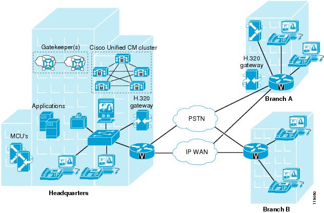
The model for a multisite WAN deployment with centralized call processing consists of a single call processing agent cluster that provides services for many remote sites and uses the IP WAN to transport Cisco Unified Communications traffic between the sites. The IP WAN also carries call control signaling between the central site and the remote sites. Figure 2-2 illustrates a typical centralized call processing deployment, with a Unified CM cluster as the call processing agent at the central site and an IP WAN with QoS enabled to connect all the sites. The remote sites rely on the centralized Unified CM cluster to handle their call processing. Applications such as voicemail, presence servers, interactive voice response (IVR) systems, and so forth, are typically centralized as well to reduce the overall costs of administration and maintenance.
Note
Figure 2-2 Multisite Deployment with Centralized Call Processing
The multisite model with centralized call processing has the following design characteristics:
•
•
•
•
•
•
•
•
•
•
•
•
•
•
•
•
•
•
Connectivity options for the IP WAN include:
•
•
•
•
•
•
Routers that reside at the WAN edges require quality of service (QoS) mechanisms, such as priority queuing and traffic shaping, to protect the voice traffic from the data traffic across the WAN, where bandwidth is typically scarce. In addition, a call admission control scheme is needed to avoid oversubscribing the WAN links with voice traffic and deteriorating the quality of established calls. For centralized call processing deployments, the locations construct within Unified CM provides call admission control. (Refer to the section on Unified CM Static Locations, page 9-13, for more information on locations.)
A variety of Cisco gateways can provide the remote sites with PSTN access. When the IP WAN is down, or if all the available bandwidth on the IP WAN has been consumed, users at the remote sites can dial the PSTN access code and place their calls through the PSTN. The Cisco Unified Survivable Remote Site Telephony (SRST) feature, available for both SCCP and SIP phones, provides call processing at the branch offices for Cisco Unified IP Phones if they lose their connection to the remote primary, secondary, or tertiary Unified CM or if the WAN connection is down. Cisco Unified SRST functionality is available on Cisco IOS gateways running the SRST feature or on Cisco Unified CME Release 4.0 and higher running in SRST mode. Unified CME running in SRST mode provides more features for the phones than SRST on a Cisco IOS gateway.
Best Practices for the Centralized Call Processing Model
Follow these guidelines and best practices when implementing the multisite WAN model with centralized call processing:
•
•
•
–
–
–
–
–
–
If a distributed call processing model is deemed more suitable for the customer's business needs, the choices include installing a Unified CM cluster at each site or running Unified CME at the remote sites.
•
–
–
–
SRST or Unified CME in SRST mode, SIP SRST, and MGCP Gateway Fallback can reside with each other on the same Cisco IOS gateway.
Remote Site Survivability
When deploying Cisco Unified Communications across a WAN with the centralized call processing model, you should take additional steps to ensure that data and voice services at the remote sites are highly available. Table 2-2 summarizes the different strategies for providing high availability at the remote sites. The choice of one of these strategies may depend on several factors, such as specific business or application requirements, the priorities associated with highly available data and voice services, and cost considerations.
The first two solutions listed in Table 2-2 provide high availability at the network infrastructure layer by adding redundancy to the IP WAN access points, thus maintaining IP connectivity between the remote IP phones and the centralized Unified CM at all times. These solutions apply to both data and voice services, and are entirely transparent to the call processing layer. The options range from adding a redundant IP WAN link at the branch router to adding a second branch router platform with a redundant IP WAN link.
The third and forth solutions in Table 2-2 use an ISDN backup link to provide survivability during WAN failures. The two deployment options for ISDN backup are:
•
With this option, ISDN is used for data survivability only, while SRST or Unified CME is used for voice survivability. Note that you should configure an access control list on the branch router to prevent Skinny Client Control Protocol (SCCP) or Session Initiation Protocol (SIP) traffic from entering the ISDN interface, so that signaling from the IP phones does not reach the Unified CM at the central site.
•
With this option, ISDN is used for both data and voice survivability. In this case, SRST or Unified CME is not used because the IP phones maintain IP connectivity to the Unified CM cluster at all times. However, Cisco recommends that you use ISDN to transport data and voice traffic only if all of the following conditions are true:
–
–
–
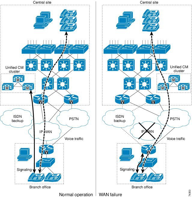
The fifth solution listed in Table 2-2, Survivable Remote Site Telephony (SRST) or Unified CME in SRST mode, provides high availability for voice services only, by providing a subset of the call processing capabilities within the remote office router and enhancing the IP phones with the ability to "re-home" to the call processing functions in the local router if a WAN failure is detected. Figure 2-3 illustrates a typical call scenario with SRST or Unified CME in SRST mode.
Figure 2-3 Survivable Remote Site Telephony (SRST) or Unified CME in SRST Mode
Under normal operations shown in the left part of Figure 2-3, the branch office connects to the central site via an IP WAN, which carries data traffic, voice traffic, and call signaling. The IP phones at the branch office exchange call signaling information with the Unified CM cluster at the central site and place their calls across the IP WAN. The branch router or gateway forwards both types of traffic (call signaling and voice) transparently and has no knowledge of the IP phones.
If the WAN link to the branch office fails, or if some other event causes loss of connectivity to the Unified CM cluster, the branch IP phones re-register with the branch router in SRST mode. The branch router, SRST, or Unified CME running in SRST mode, queries the IP phones for their configuration and uses this information to build its own configuration automatically. The branch IP phones can then make and receive calls either internally or through the PSTN. The phone displays the message "Unified CM fallback mode," and some advanced Unified CM features are unavailable and are grayed out on the phone display.
When WAN connectivity to the central site is reestablished, the branch IP phones automatically re-register with the Unified CM cluster and resume normal operation. The branch SRST router deletes its information about the IP phones and reverts to its standard routing or gateway configuration. Unified CME running in SRST mode at the branch can choose to save the learned phone and line configuration to the running configuration on the Unified CME router by using the auto-provision option. If auto-provision none is configured, none of the auto-provisioned phone or line configuration information is written to the running configuration of the Unified CME router. Hence, no configuration change is required on Unified CME if the IP phone is replaced and the MAC address changes.
Note
Unified CME in SRST Mode
When Unified CME is used in SRST mode, it provides more call processing features for the IP phones than are available with the SRST feature on a router. In addition to the SRST features such as call preservation, auto-provisioning, and failover, Unified CME in SRST mode also provides most of the Unified CME telephony features for the SCCP phones, including:
•
•
•
•
•
•
•
•
•
Unified CME in SRST mode provides call processing support for SCCP phones in case of a WAN failure. However, Unified CME in SRST mode does not provide fallback support for SIP phones or MGCP phones or endpoints. To enable SIP and MGCP phones to fall back if they lose their connection to the SIP proxy server or Unified CM, or if the WAN connection fails, you can additionally configure both the SIP SRST feature and the MGCP Gateway Fallback feature on the same Unified CME server running as the SRST fallback server.
Best Practices for Unified CME in SRST Mode
•
•
•
•
•
For more information on using Unified CME in SRST mode, refer to the Cisco Unified Communications Manager Express System Administrator Guide, available at
For more information on SIP SRST, refer to the Cisco Unified SIP SRST System Administrator Guide, available at
For more information on MGCP Gateway fallback, refer to the information on MGCP gateway fallback in the Cisco CallManager and Cisco IOS Interoperability Guide, available at
http://www.cisco.com/en/US/docs/ios/12_3/vvf_c/interop/ccm_c.html
Best Practices for SRST Router
Use a Cisco Unified SRST router, rather than Unified CM in SRST mode, for the following deployment scenarios:
•
•
•
•
•
•
Voice Over the PSTN as a Variant of Centralized Call Processing
The centralized call processing deployment model can be adapted so that inter-site voice media is sent over the PSTN instead of the WAN. With this configuration, the signaling (call control) of all telephony endpoints is still controlled by the central Unified CM cluster, therefore this Voice over the PSTN (VoPSTN) model variation still requires a QoS-enabled WAN with appropriate bandwidth configured for the signaling traffic.
You can implement VoPSTN in one of the following ways:
•
•
VoPSTN can be an attractive option in deployments where IP WAN bandwidth is either scarce or expensive with respect to PSTN charges, or where IP WAN bandwidth upgrades are planned for a later date but the Cisco Unified Communications system is already being deployed.
Note
In particular, regardless of the implementation choice, the system designer should address the following issues, among others:
•
–
–
•
•
•
•
•
•
•
•
–
–
The gateway port utilization resulting from these call forwarding flows should be taken into account when sizing the trunks connecting the branch to the PSTN.
•
•
–
–
–
•
•
•
In addition to these general considerations, the following sections present recommendations and issues specific to each of the following implementation methods:
VoPSTN Using AAR
This method consists of configuring the Unified CM dial plan as in a traditional centralized call processing deployment, with the automated alternate routing (AAR) feature also properly configured. AAR provides transparent re-routing over the PSTN of inter-site calls when the locations mechanism for call admission control determines that there is not enough available WAN bandwidth to accept an additional call.
To use the PSTN as the primary (and only) voice path, you can configure the call admission control bandwidth of each location (branch site) to be 1 kbps, thus preventing all calls from traversing the WAN. With this configuration, all inter-site calls trigger the AAR functionality, which automatically re-routes the calls over the PSTN.
The AAR implementation method for VoPSTN offers the following benefits:
•
•
In addition to the general considerations listed for VoPSTN, the following design guidelines apply to the AAR implementation method:
•
•
•
•
•
•
•
•
–
–
Note
VoPSTN Using Dial Plan
This method relies on a specific dial plan configuration within Unified CM and the PSTN gateways to route all inter-site calls over the PSTN. The dial plan must place IP phone DN's at each site into a different partition, and their calling search space must provide access only to the site's internal partition and a set of route patterns that point to the local PSTN gateway.
Abbreviated inter-site dialing can still be provided via a set of translations at each branch site, one for each of the other branch sites. These translations are best accomplished with H.323 gateways and translation rules within Cisco IOS.
The dial plan method for implementing VoPSTN offers the following benefits:
•
•
In addition to the general considerations listed for VoPSTN, the following design guidelines apply to the dial plan implementation method:
•
•
•
Multisite WAN with Distributed Call Processing
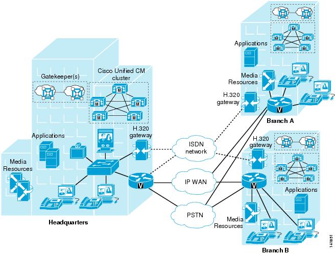
The model for a multisite WAN deployment with distributed call processing consists of multiple independent sites, each with its own call processing agent cluster connected to an IP WAN that carries voice traffic between the distributed sites. Figure 2-4 illustrates a typical distributed call processing deployment.
Figure 2-4 Multisite Deployment with Distributed Call Processing
Each site in the distributed call processing model can be one of the following:
•
–
–
–
•
•
The multisite model with distributed call processing has the following design characteristics:
•
•
•
•
•
•
•
•
•
•
•
•
•
An IP WAN interconnects all the distributed call processing sites. Typically, the PSTN serves as a backup connection between the sites in case the IP WAN connection fails or does not have any more available bandwidth. A site connected only through the PSTN is a standalone site and is not covered by the distributed call processing model. (See Single Site.)
Connectivity options for the IP WAN include:
•
•
•
•
•
•
Benefits of the Distributed Call Processing Model
The multisite WAN model with distributed call processing provides the following benefits:
•
•
•
•
•
Best Practices for the Distributed Call Processing Model
A multisite WAN deployment with distributed call processing has many of the same requirements as a single site or a multisite WAN deployment with centralized call processing. Follow the best practices from these other models in addition to the ones listed here for the distributed call processing model. (See Single Site, and Multisite WAN with Centralized Call Processing.)
Gatekeeper or Session Initiation Protocol (SIP) proxy servers are among the key elements in the multisite WAN model with distributed call processing. They each provide dial plan resolution, with the gatekeeper also providing call admission control. A gatekeeper is an H.323 device that provides call admission control and E.164 dial plan resolution.
The following best practices apply to the use of a gatekeeper:
•
•
•
•
•
For more information on the various functions performed by gatekeepers, refer to the following sections:
•
•
•
SIP devices provide resolution of E.164 numbers as well as SIP uniform resource identifiers (URIs) to enable endpoints to place calls to each other. Unified CM supports the use of E.164 numbers only.
The following best practices apply to the use of SIP proxies:
•
•
•
Call Processing Agents for the Distributed Call Processing Model
Your choice of call processing agent will vary, based on many factors. The main factors, for the purpose of design, are the size of the site and the functionality required.
For a distributed call processing deployment, each site has its own call processing agent. The design of each site varies with the call processing agent, the functionality required, and the fault tolerance required. For example, in a site with 500 phones, a Unified CM cluster containing two servers can provide one-to-one redundancy, with the backup server being used as a publisher and Trivial File Transfer Protocol (TFTP) server.
The requirement for IP-based applications also greatly affects the choice of call processing agent because only Unified CM provides the required support for many Cisco IP applications.
Table 2-3 lists recommended call processing agents.
Clustering Over the IP WAN
You may deploy a single Unified CM cluster across multiple sites that are connected by an IP WAN with QoS features enabled. This section provides a brief overview of clustering over the WAN. For further information, refer to the chapter on Call Processing, page 8-1.
Clustering over the WAN can support two types of deployments:
•
Local failover requires that you place the Unified CM subscriber and backup servers at the same site, with no WAN between them. This deployment model is ideal for two to four sites with Unified CM.
•
Remote failover allows you to deploy primary and backup call processing servers split across the WAN. Using this deployment model, you may have up to eight sites with Unified CM subscribers being backed up by Unified CM subscribers at another site.
Note
You can also use a combination of the two deployment models to satisfy specific site requirements. For example, two main sites may each have primary and backup subscribers, with another two sites containing only a primary server each and utilizing either shared backups or dedicated backups at the two main sites.
Some of the key advantages of clustering over the WAN are:
•
•
•
•
•
These features make this solution ideal as a disaster recovery plan for business continuance sites or as a single solution for up to eight small or medium sites.
WAN Considerations
For clustering over the WAN to be successful, you must carefully plan, design, and implement various characteristics of the WAN itself. The Intra-Cluster Communication Signaling (ICCS) between Unified CM servers consists of many traffic types. The ICCS traffic types are classified as either priority or best-effort. Priority ICCS traffic is marked with IP Precedence 3 (DSCP 24 or PHB CS3). Best-effort ICCS traffic is marked with IP Precedence 0 (DSCP 0 or PHB BE). The various types of ICCS traffic are described in Intra-Cluster Communications, which also provides further guidelines for provisioning. The following design guidelines apply to the indicated WAN characteristics:
•
The maximum one-way delay between any two Unified CM 6.0 servers should not exceed 20 msec, or 40 msec round-trip time (RTT). Beginning with Cisco Unified CM Release 6.1, the maximum one-way delay between two Unified CM servers can be up to 40 msec, or 80 msec round-trip time. Measuring the delay is covered in Delay Testing.
•
Jitter is the varying delay that packets incur through the network due to processing, queue, buffer, congestion, or path variation delay. Jitter for the IP Precedence 3 ICCS traffic must be minimized using Quality of Service (QoS) features.
•
The network should be engineered to provide sufficient prioritized bandwidth for all ICCS traffic, especially the priority ICCS traffic. Standard QoS mechanisms must be implemented to avoid congestion and packet loss. If packets are lost due to line errors or other "real world" conditions, the ICCS packet will be retransmitted because it uses the TCP protocol for reliable transmission. The retransmission might result in a call being delayed during setup, disconnect (teardown), or other supplementary services during the call. Some packet loss conditions could result in a lost call, but this scenario should be no more likely than errors occurring on a T1 or E1, which affect calls via a trunk to the PSTN/ISDN.
•
Provision the correct amount of bandwidth between each server for the expected call volume, type of devices, and number of devices. This bandwidth is in addition to any other bandwidth for other applications sharing the network, including voice and video traffic between the sites. The bandwidth provisioned must have QoS enabled to provide the prioritization and scheduling for the different classes of traffic. The general rule of thumb for bandwidth is to over-provision and under-subscribe.
•
The network infrastructure relies on QoS engineering to provide consistent and predictable end-to-end levels of service for traffic. Neither QoS nor bandwidth alone is the solution; rather, QoS-enabled bandwidth must be engineered into the network infrastructure.
Intra-Cluster Communications
In general, intra-cluster communications means all traffic between servers. There is also a real-time protocol called Intra-Cluster Communication Signaling (ICCS), which provides the communications with the Cisco CallManager Service process that is at the heart of the call processing in each server or node within the cluster.
The intra-cluster traffic between the servers consists of the following:
•
•
•
•
Note
Unified CM Publisher
The publisher server replicates a partial read-only copy of the master database to all other servers in the cluster. Most of the database modifications are done on the publisher. If changes such as administration updates are made in the publisher's master database during a period when another server in the cluster is unreachable, the publisher will replicate the updated database when communications are re-established. Database modifications for user-facing call processing features are made on the subscriber servers to which the IP phones are registered. These features include:
•
•
•
•
•
•
•
•
•
•
Each subscriber replicates these changes to every other server in the cluster. Any other configuration changes cannot be made on the database during the period when the publisher is unreachable or offline. Most normal operations of the cluster, including the following, will not be affected during the period of publisher failure:
•
•
•
Other services or applications might also be affected, and their ability to function without the publisher should be verified when deployed.
Call Detail Records (CDR) and Call Management Records (CMR)
Call detail records and call management records, when enabled, are collected by each subscriber and uploaded to the publisher periodically. During a period that the publisher is unreachable, the CDRs and CMRs are stored on the subscriber's local hard disk. When connectivity is re-established to the publisher, all outstanding CDRs are uploaded to the publisher, which stores the records in the CDR Analysis and Reporting (CAR) database.
Delay Testing
The maximum round-trip time (RTT) between any two servers must not exceed 40 msec for Unified CM 6.0, or 80 msec for Unified CM 6.1 and later releases. This time limit must include all delays in the transmission path between the two servers. Verifying the round trip delay using the ping utility on the Unified CM server will not provide an accurate result. The ping is sent as a best-effort tagged packet and is not transported using the same QoS-enabled path as the ICCS traffic. Therefore, Cisco recommends that you verify the delay by using the closest network device to the Unified CM servers, ideally the access switch to which the server is attached. Cisco IOS provides a extended ping capable to set the Layer 3 type of service (ToS) bits to make sure the ping packet is sent on the same QoS-enabled path that the ICCS traffic will traverse. The time recorded by the extended ping is the round-trip time (RTT), or the time it takes to traverse the communications path and return.
The following example shows a Cisco IOS extended ping with the ToS bit (IP Precedence) set to 3:
Access_SW#pingProtocol [ip]:Target IP address: 10.10.10.10Repeat count [5]:Datagram size [100]:Timeout in seconds [2]:Extended commands [n]: ySource address or interface:Type of service [0]: 3Set DF bit in IP header? [no]:Validate reply data? [no]:Data pattern [0xABCD]:Loose, Strict, Record, Timestamp, Verbose[none]:Sweep range of sizes [n]:Type escape sequence to abort.Sending 5, 100-byte ICMP Echos to 10.10.10.10, timeout is 2 seconds:!!!!!Success rate is 100 percent (5/5), round-trip min/avg/max = 1/2/4 msError Rate
The expected error rate should be zero. Any errors, dropped packets, or other impairments to the IP network can have an impact to the call processing performance of the cluster. This may be noticeable by delay in dial tone, slow key or display response on the IP phone, or delay from off-hook to connection of the voice path. Although Unified CM will tolerate random errors, they should be avoided to avoid impairing the performance of the cluster.
Troubleshooting
If the Unified CM subscribers in a cluster are experiencing impairment of the ICCS communication due to higher than expected delay, errors, or dropped packets, some of the following symptoms might occur:
•
•
•
•
•
In summary, perform the following tasks to troubleshoot ICCS communication problems:
•
•
•
•
Local Failover Deployment Model
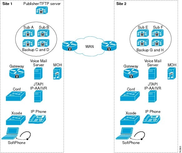
The local failover deployment model provides the most resilience for clustering over the WAN. Each of the sites in this model contains at least one primary Unified CM subscriber and one backup subscriber. This configuration can support up to four sites. The maximum number of phones and other devices will be dependant on the quantity and type of servers deployed. The maximum total number of IP phones for all sites is 30,000. (See Figure 2-5.)
Figure 2-5 Example of Local Failover Model
Observe the following guidelines when implementing the local failover model:
•
•
•
•
•
•
Note
•
•
Total Bandwidth (Mbps) = (Total BHCA/10,000) * (1 + 0.006 * Delay), where Delay = RTT delay in msec
This call control traffic is classified as priority traffic. Priority ICCS traffic is marked with IP Precedence 3 (DSCP 24 or PHB CS3).
•
Example 2-1 Bandwidth Calculation for Two Sites
Consider two sites, Site 1 and Site 2, with Unified CM clustered over the WAN across these two sites that are 80 msec round-trip time apart. Site 1 has one publisher, one combined TFTP and music on hold (MoH) server, and two Unified CM subscriber servers. Site 2 has one TFTP/MoH server and two Unified CM subscriber servers. Site 1 has 5000 phones, each having one DN; and Site 2 has 5000 phones, each having one DN. During the busy hour, 2500 phones in Site 1 call 2500 phones in Site 2, each at 3 BHCA. During that same busy hour, 2500 phones in Site 2 also call 2500 phones in Site 1, each at 3 BHCA. In this case:
Total BHCA during the busy hour = 2500*3 + 2500*3 = 15,000
Total bandwidth required between the sites = Total ICCS bandwidth + Total database bandwidth
Because total BHCA is 15,000 (greater than 10,000), we can use the formula to calculate: Total ICCS bandwidth = (15,000/10,000) * (1 + 0.006*80) = 2.22 Mbps
Total database bandwidth = (Number of servers remote to the publisher) * 1.544 = 3 * 1.544 = 4.632 Mbps
Total bandwidth required between the sites = 2.22 Mbps + 4.632 Mbps = 6.852 Mbps (Approximately 7 Mbps)
•
Overhead = (0.012 * Delay * Shared-line) + (0.65 * Shared-line), where:
Delay = RTT delay over the IP WAN, in msec
Shared-line = Average number of additional phones on which a directory number is shared across the WAN.
The following equation may be used as a guideline to calculate the bandwidth for more than 10,000 BHCA between shared directory numbers at a specific delay:
Total bandwidth (Mbps) = (Total BHCA/10,000) * (1 + 0.006 * Delay + 0.012 * Delay * Shared-line + 0.65 * Shared-line), where:
Delay = RTT delay in msec
Shared-line = Average number of additional phones on which a directory number is shared across the WAN.
Example 2-2 Bandwidth Calculation for Two Sites with Shared Directory Numbers
Consider two sites, Site 1 and Site 2, with Unified CM clustered over the WAN across these two sites that are 80 msec round-trip time apart. Site 1 has one publisher, one combined TFTP and music on hold (MoH) server, and two Unified CM subscriber servers. Site 2 has one TFTP/MoH server and two Unified CM subscriber servers. Site 1 has 5000 phones, each having one DN; and Site 2 has 5000 phones, each sharing a DN with the 5000 phones in Site 1. Thus, each DN is shared across the WAN with an average of one additional phone. During the busy hour, 2500 phones in Site 1 call 2500 phones in Site 2, each at 3 BHCA. This also causes the phones in Site 1 to ring. During that same busy hour, 2500 phones in Site 2 call 2500 phones in Site 1, each at 3 BHCA. This also causes the phones in Site 2 to ring. In this case:
Total BHCA during the busy hour = 2500 * 3 + 2500 * 3 = 15,000
Total bandwidth required between the sites = Total ICCS bandwidth + Total database bandwidth
Because total BHCA is 15,000 (greater than 10,000), we can use the formula to calculate: Total ICCS bandwidth = (15,000/10,000) * (1 + 0.006*80 + 0.012*80*1 + 0.65*1) = 4.635 Mbps
Total database bandwidth = (Number of servers remote to the publisher) * 1.544 = 3 * 1.544 = 4.632 Mbps
Total bandwidth required between the sites = 4.635 Mbps + 4.632 Mbps = 9.267 Mbps (Approximately 10 Mbps)
Note
•
Note
•
–
–
–
•
Unified CM Provisioning for Local Failover
Provisioning of the Unified CM cluster for the local failover model should follow the design guidelines for capacities outlined in the chapter on Call Processing, page 8-1. If voice or video calls are allowed across the WAN between the sites, then you must configure Unified CM locations in addition to the default location for the other sites, to provide call admission control between the sites. If the bandwidth is over-provisioned for the number of devices, it is still best practice to configure call admission control based on locations. If the locations-based call admission control rejects a call, automatic failover to the PSTN can be provided by the automated alternate routing (AAR) feature.
To improve redundancy and upgrade times, Cisco recommends that you enable the Cisco Trivial File Transfer Protocol (TFTP) service on two Unified CM servers. More than two TFTP servers can be deployed in a cluster, however this configuration can result in an extended period for rebuilding all the TFTP files on all TFTP servers.
You can run the TFTP service on either a publisher or a subscriber server, depending on the site and the available capacity of the server. The TFTP server option must be correctly set in the DHCP servers at each site. If DHCP is not in use or if the TFTP server is manually configured, you should configure the correct address for the site.
Other services, which may affect normal operation of Unified CM during WAN outages, should also be replicated at all sites to ensure uninterrupted service. These services include DHCP servers, DNS servers, corporate directories, and IP phone services. On each DHCP server, set the DNS server address correctly for each location.
IP phones may have shared line appearances between the sites. During a WAN outage, call control for each line appearance is segmented, but call control returns to a single Unified CM server once the WAN is restored. During the WAN restoration period, there is additional traffic between the two sites. If this situation occurs during a period of high call volume, the shared lines might not operate as expected during that period. This situation should not last more than a few minutes, but if it is a concern, you can provision additional prioritized bandwidth to minimize the effects.
Gateways for Local Failover
Normally, gateways should be provided at all sites for access to the PSTN. The device pools should be configured to register the gateways with the Unified CM servers at the same site. Partitions and calling search spaces should also be configured to select the local gateways at the site as the first choice for PSTN access and the other site gateways as a second choice for overflow. Take special care to ensure emergency service access at each site.
You can centralize access to the PSTN gateways if access is not required during a WAN failure and if sufficient additional bandwidth is configured for the number of calls across the WAN. For E911 requirements, additional gateways might be needed at each site.
Voicemail for Local Failover
Cisco Unity or other voicemail systems can be deployed at all sites and integrated into the Unified CM cluster. This configuration provides voicemail access even during a WAN failure and without using the PSTN. Using Voice Mail Profiles, you can allocate the correct voicemail system for the site to the IP phones in the same location. You can configure a maximum of four voicemail systems per cluster that use the SMDI protocol, that are attached directly to the COM port on a subscriber, and that use the Cisco Messaging Interface (CMI).
Music on Hold and Media Resources for Local Failover
Music on hold (MoH) servers and other media resources such as conference bridges should be provisioned at each site, with sufficient capacity for the type and number of users. Through the use of media resource groups (MRGs) and media resource group lists (MRGLs), media resources are provided by the on-site resource and are available during a WAN failure.
Remote Failover Deployment Model
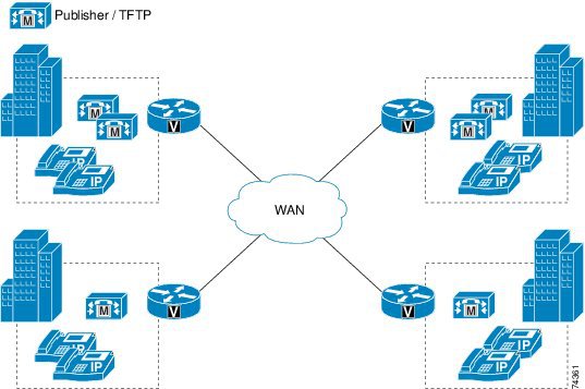
The remote failover deployment model provides flexibility for the placement of backup servers. Each of the sites contains at least one primary Unified CM subscriber and may or may not have a backup subscriber. This model allows for a deployment of up to eight sites, with IP phones and other devices normally registered to a local subscriber when using 1:1 redundancy and the 50/50 load balancing option described in the chapter on Call Processing, page 8-1. Backup subscribers are located across the WAN at one or more of the other sites. (See Figure 2-6.)
Figure 2-6 Remote Failover Model with Four Sites
When implementing the remote failover model, observe all guidelines for the local failover model (see Local Failover Deployment Model), with the following modifications:
•
•
•
Note
Design Considerations for Section 508 Conformance
Regardless of which deployment model you choose, you should consider designing your Cisco Unified Communications network to make the telephony features more accessible to users with disabilities, in conformance with Section 255 of the Telecommunications Act and U.S. Section 508.
Observe the following basic design guidelines when configuring your Cisco Unified Communications network to conform to Section 508:
•
•
•
•
•
•
•
–
Plug a TTY/TDD with an RJ-11 analog line option directly into a Cisco FXS port. Any FXS port will work, such as the one on the Cisco VG248, Catalyst 6000, Cisco ATA 188 module, or any other Cisco voice gateway with an FXS port. Cisco recommends this method of connection.
–
Place the IP phone handset into a coupling device on the TTY/TDD. Acoustic coupling is less reliable than an RJ-11 connection because the coupling device is generally more susceptible to transmission errors caused by ambient room noise and other factors.
•