-
Cisco CallManager Features and Services Guide, Release 4.1(2)
-
Index
-
Preface
-
Cisco CallManager Extension Mobility
-
Cisco IP Manager Assistant With Proxy Line Support
-
Cisco IP Manager Assistant With Shared Line Support
-
Cisco Call Back
-
Client Matter Codes and Forced Authorization Codes
-
Music On Hold
-
Cisco CallManager AutoAttendant
-
Barge and Privacy
-
Call Park
-
Immediate Divert
-
Malicious Call Identification
-
Multilevel Precedence and Preemption
-
Custom Phone Rings
-
Cisco WebDialer
-
Cisco CallManager Attendant Console
-
Call Display Restrictions
-
Quality Report Tool
-
External Call Transfer Restrictions
-
Troubleshooting Features and Services
-
 Feedback
Table Of Contents
Introducing Quality Report Tool
Cisco CTIManager Interface (QBEHelper)
Cisco CallManager Database Interface (DBL Library)
Cisco Extended Functions Service Dependency
Multiple Cisco Extended Functions Applications in a Cluster
Problem Classification Categories and Reason Codes
Installing and Activating QRT Functions
Configuration Checklist for QRT
Creating a Softkey Template with the QRT Softkey
Configuring the QRT Softkey Template in Device Pool
Adding the QRT Softkey Template in Phone Configuration
Configuring the Cisco CallManager Serviceability Features
Activating the Cisco Extended Functions Service for QRT
Configuring Alarms and Traces for QRT
Setting the Cisco Extended Functions Service Parameters for QRT
Providing Information to Users for the QRT Feature
Troubleshooting the QRT Feature
Where to Find More Information
Quality Report Tool
The Quality Report Tool (QRT), a voice-quality and general problem-reporting tool for Cisco IP Phones, acts as a Windows NT service that allows users to easily and accurately report audio and other general problems with their IP phone. QRT automatically loads with the Cisco CallManager installation, and the Cisco Extended Functions (CEF) service supports it. (For more information about the Cisco Extended Functions service, refer to Services in the Cisco CallManager System Guide.)
As system administrator, you can enable QRT functionality by creating, configuring, and assigning a softkey template to associate the QRT softkey on a user's IP phone. You can choose from two different user modes, depending upon the amount of user interaction that is desired with QRT.
Note
The system gives users with administrator privileges the authorization to configure QRT and view the reports.
This chapter provides the following information about configuring and using the QRT feature:
•
•
•
•
•
•
•
Introducing Quality Report Tool
When you install Cisco CallManager, the Cisco Extended Functions service installs and loads the QRT functionality on the Cisco CallManager server.
Then, as system administrator, you enable the QRT feature through the use of softkey templates and define how the feature will work in your system by configuring system parameters and setting up Cisco CallManager Serviceability tools. You can then create, customize, and view phone problem reports by using the QRT Viewer application.
You can configure QRT availability for up to four different call states and choose from two different user modes. The user modes determine the level of user interaction that is enabled with QRT and allow either detailed voice-quality reports or more general phone problem reports, and relevant statistics. (See the "Extended Menu Choices" section for more information.)
When users experience problems with their IP phones, they can invoke this feature by pressing the QRT softkey on their Cisco IP Phone during one of the following call states:
•
•
•
•
From a supported call state, and using the appropriate problem classification category, users can then choose the reason code that best describes the problem that they are experiencing with their IP phone. See the "Problem Classification Categories and Reason Codes" section for specific information about problem categories, reason codes, and supported call states.
The Quality Report Tool comprises several key components. The following sections provide information about these components and the architecture of the QRT feature:
Components of QRT
QRT, a multitiered, web-based application, includes the following key components:
•
•
•
•
•
•
•
•
•
•
•
•
•
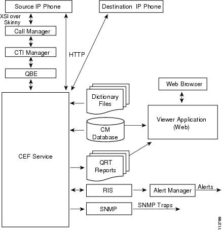
Overview of QRT Architecture
The QRT feature uses the Cisco Extended Functions service, which comprises the following interfaces:
•
•
The Cisco Extended Functions service interfaces with the phone by using the XML services interface (XSI) over skinny protocol (a protocol that is used between a Cisco IP Phone and Cisco CallManager) and the Quick Byte Encoding protocol (a protocol that is used between the Cisco CTIManager and TSP/JTAPI).
When a user presses the QRT softkey, QRT opens the device and presents up to four different screens that display problem categories and associated reason codes to obtain user feedback.
After the user chooses the option that best describes the problem, the system logs the feedback in the XML file; the system then issues alarms to notify the Cisco RIS Data Collector to generate alerts and SNMP traps. When QRT detects that user interaction is complete, it then closes the device.
Note
Figure 17-1 shows an illustration of the Cisco Extended Functions service architecture.
Figure 17-1 Using the Cisco Extended Functions Service Architecture
Cisco CTIManager Interface (QBEHelper)
The QBEHelper library provides the interface that allows the Cisco Extended Functions service to communicate with a configured Cisco CTIManager.
Cisco CallManager Database Interface (DBL Library)
The DBL library provides the interface that allows the Cisco Extended Functions service to perform queries on various devices that are configured and registered in the Cisco CallManager database.
Screen Helper and Dictionary
The screen helper of the Cisco Extended Functions service reads the XML dictionary files and creates Document Object Model (DOM) objects for all installed locales when the CEF service starts. The system uses these DOM objects for constructing XSI screens that the Cisco IP Phone needs.
Redundancy Manager
When multiple Cisco Extended Functions are active within a Cisco CallManager cluster, the redundancy manager uses an algorithm to determine which Cisco Extended Functions service is active and which is the backup CEF. The Redundancy Manager uses the lowest IP address of the server that is running the CEF service as the active service. The remaining CEF services serve as backup services.
DB Change Notifier
The DB Change Notifier handles all the database change notifications, such as service parameter changes, trace parameter changes, alarm configuration changes, and status changes of other CEF services in the cluster, and reports the changes to the Cisco Extended Functions service.
SDI Trace and Alarm
The Cisco Extended Functions service uses the SDI Trace and Alarm libraries. The libraries generate traces and alarms to the Event Viewer. The alarm library publishes information about the CEF service to Syslog, SNMP, and the Cisco RIS Data Collector service. For more information about traces and alarms, refer to the Cisco CallManager Serviceability Administration Guide.
System Requirements for QRT
To operate, the QRT feature requires the following software components:
•
•
•
Support for the QRT feature extends to any model IP phone that includes the following capabilities:
•
•
•
•
Note
Cisco IP Phone guide for your model IP phone:
http://www.cisco.com/univercd/cc/td/doc/product/voice/c_ipphon/index.htm.
Cisco Extended Functions Service Dependency
The Cisco Extended Functions service depends on the following services:
•
•
•
•
Note
Tip
Figure 17-2 shows a typical Cisco Extended Functions service configuration.
Figure 17-2 Cisco Extended Functions Service Dependency (Typical Configuration)
Multiple Cisco Extended Functions Applications in a Cluster
If multiple Cisco Extended Functions services are active within a Cisco CallManager cluster, Cisco Extended Functions uses an algorithm to determine which service should be active and to order the remaining as backups. The Cisco Extended Functions application with the lowest IP address becomes active. The service with the next lowest IP address becomes the backup to the active service. Any remaining services act as backups to each other, beginning with the service with the next lowest IP address. If you add any new services to the cluster, Cisco Extended Functions restarts the algorithm to determine which service will be active.
Note
To verify the directory status and Cisco Extended Functions service registration status to the Cisco CTIManager, use the Real-Time Monitoring Tool (RTMT) as described in the Cisco CallManager Serviceability Administration Guide.
How to Use QRT
After you properly install and configure QRT, supported Cisco IP Phones include the QRT softkey. (See the "System Requirements for QRT" section for the IP phone models that are supported with QRT.)
Note
The following sections describe the user interaction features with QRT:
•
For more user-related information, refer to the following URL for the appropriate Cisco IP Phone guide for your phone model:
http://www.cisco.com/univercd/cc/td/doc/product/voice/c_ipphon/index.htm.User Interface
The QRT user interface includes several components, as described below:
•
Only the Cisco CallManager administrator can access the following components:
•
•
•
•
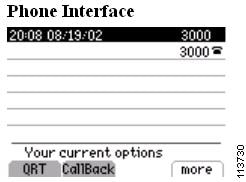
Figure 17-3 shows an example of the QRT softkey as it displays on a
Cisco IP Phone.Figure 17-3 QRT Phone Interface Display
Extended Menu Choices
Extended menu choices allow a user to interact with QRT and provide additional details regarding the phone problem that they are reporting. You can choose to enable extended menu choices or provide users with a more passive interface, depending upon the amount of information that you want users to submit.
From the Cisco CallManager Service Parameters Configuration window, configure the user interface mode for QRT from the following options:
•
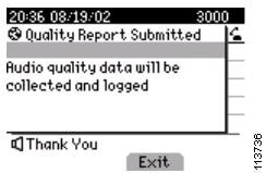
The system supports silent mode only when the IP phone is in the Connected, Connected Conference, or Connected Transfer call state.
Figure 17-4 shows an example of the QRT display as it appears in silent mode.
Figure 17-4 Submitting Voice Quality Feedback in Silent Mode
•
The system supports interview mode only when the IP phone is in the Connected or On Hook call state.
Figure 17-5 shows an example of the QRT display as it appears when the QRT softkey is pressed while the phone is on-hook and in interview mode.
Figure 17-5 QRT Phone Interface - On Hook, Interview Mode Display
Note
Note
Problem Classification Categories and Reason Codes
The following tables show the problem categories and corresponding reason codes that users can choose to report problems with their IP phones. Additional options become available after you configure extended menu choices. Users can choose only one reason code per category, per problem. Each problem category becomes available only when the IP phone is in the supported call state.
Table 17-1 shows the supported call states and the reason codes that are available for the "Problems with current call" category.
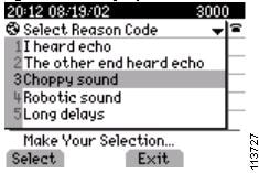
Figure 17-6 shows an example of the phone display as it appears after the QRT softkey is pressed on an IP phone in the connected state. This menu allows the user to provide additional details before submitting a problem with the current phone call.
Figure 17-6 Reporting Problem with the Current Call
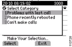
Table 17-2 shows the supported call state and the reason codes that are available for the "Problems with last call" category.
Figure 17-7 shows an example of the phone display as it appears after the user selects the "Problems with last call" category. This menu allows the user to provide additional details before submitting a problem report for the last phone call.
Figure 17-7 Reporting Problem with the Last Call
Table 17-3 shows the supported call state that is available for the "Phone recently rebooted" category. No associated reason codes exist for this category.
Table 17-3 Problem Category—Phone Recently Rebooted
Phone recently rebooted
•
None
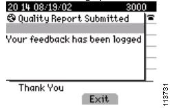
Figure 17-8 shows an example of the phone display after the user chooses the "Phone recently rebooted" category. The system logs user feedback.
Figure 17-8 Reporting Problem with Phone Recently Rebooted
Table 17-4 shows the supported call state and the reason codes that are available for the "I can't make calls" category.
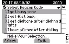
Figure 17-9 shows an example of the phone display as it appears after the user chooses the "I can't make calls" category.
Figure 17-9 Reporting Problem with I Can't Make Calls
Note
Interactions and Restrictions
The following interactions and restrictions apply when you use the QRT feature with Cisco CallManager:
•
•
•
•
•
Note
Installing and Activating QRT Functions
As a feature within the Cisco Extended Functions service, QRT automatically installs as part of the Cisco CallManager installation.
Perform the following steps after installation to enable QRT availability for users and to set up administrative reporting capabilities:
1.
2.
3.
4.
Note
Configuring the QRT Feature
For successful configuration of the QRT feature, review the steps in Table 17-5, QRT Configuration Checklist, perform the configuration requirements, activate the Cisco Extended Functions service, and set the service parameters.
The following sections provide configuration information for enabling QRT:
•
•
•
•
•
•
•
Configuration Checklist for QRT
Table 17-5 shows the steps for configuring the QRT feature in Cisco CallManager.
Table 17-5 QRT Configuration Checklist
Step 1
Create a copy of the Standard User softkey template and add the QRT softkey for the following call states:
•
•
•
•
Creating a Softkey Template with the QRT Softkey
Softkey Template Configuration, Cisco CallManager Administration Guide
Step 2
Add the new softkey template to the device pool.
Configuring the QRT Softkey Template in Device Pool
Device Pool Configuration, Cisco CallManager Administration Guide
Step 3
Add the new softkey template to the user phones by using the Phone Configuration window.
Note
Adding the QRT Softkey Template in Phone Configuration
Softkey Template Configuration, Cisco CallManager Administration Guide
Step 4
Using the Cisco CallManager Serviceability tool, Service Activation, activate Cisco Extended Functions service.
Activating the Cisco Extended Functions Service for QRT
Cisco CallManager Serviceability Administration Guide
Step 5
From Cisco CallManager Serviceability, configure alarms and traces for QRT.
Configuring Alarms and Traces for QRT
Cisco CallManager Serviceability Administration Guide
Step 6
Configure the Cisco Extended Functions service parameters for QRT.
Setting the Cisco Extended Functions Service Parameters for QRT
Step 7
Access the QRT Viewer to create, customize, and view IP phone problem reports.
Cisco CallManager Serviceability Administration Guide.
Creating a Softkey Template with the QRT Softkey
Perform the following procedure to create a new softkey template with the QRT softkey.
Procedure
Step 1
The Softkey Template Configuration window displays.
Step 2
Step 3
The Softkey Template Configuration window displays with new information.
Step 4
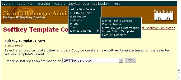
Figure 17-10 shows an example of the Cisco CallManager Administration Softkey Template window, where you copy a softkey template.
Figure 17-10 QRT Softkey Template Copy
Step 5
The Softkey Template Configuration redisplays with new information.
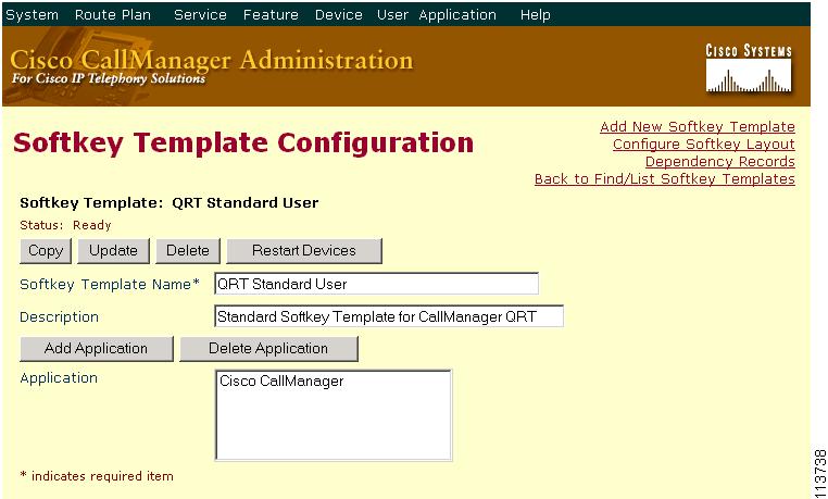
Figure 17-11 shows an example of the Cisco CallManager Administration Softkey Template Configuration window.
Figure 17-11 QRT Softkey Template Configuration
Step 6
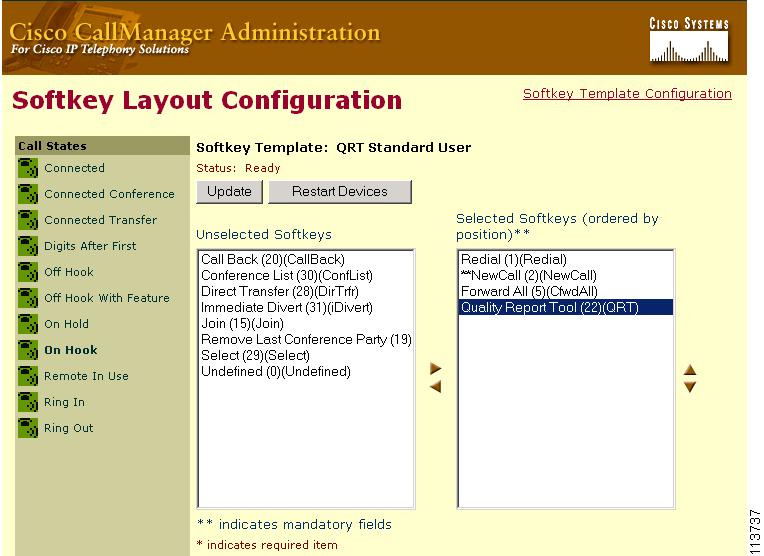
The Softkey Layout Configuration window displays. You must add the QRT softkey to the Connected, Connected Conference, Connected Transfer, and On Hook call states.
Step 7
The Softkey Layout Configuration window redisplays with the Unselected Softkeys and Selected Softkeys lists.
Step 8
Figure 17-12 shows an example of the Cisco CallManager Administration Softkey Layout Configuration window.
Figure 17-12 QRT Softkey Layout Configuration
Step 9
Step 10
Note
Configuring the QRT Softkey Template in Device Pool
Perform the following procedure to add the QRT softkey template to the device pool.
Procedure
Step 1
The Device Pool Configuration window displays.
Step 2
You can add the template to the default device pool if you want all users to have access to the QRT softkey, or you can create a customized device pool for QRT feature users.
Step 3
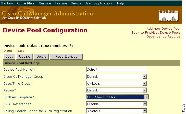
Figure 17-13 shows an example of the Cisco CallManager Administration Device Pool Configuration window.
Figure 17-13 Device Pool Configuration
Note
Step 4
Adding the QRT Softkey Template in Phone Configuration
Perform the following procedure to add the QRT softkey template to each user phone.
Procedure
Step 1
The Find and List Phones window displays.
Step 2
Step 3
If you alternatively configured the softkey template in the device pool, from the Device Pool field, choose the device pool that contains the new softkey template.
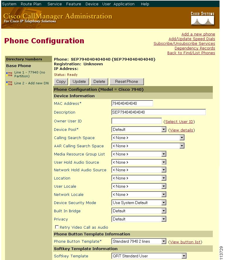
Figure 17-14 shows an example of the Cisco CallManager Administration Phone Configuration window.
Figure 17-14 Phone Configuration
Step 4
Configuring the Cisco CallManager Serviceability Features
The Cisco Extended Functions service uses the following Cisco CallManager Serviceability features:
•
•
•
•
This section describes how to activate and configure the Cisco CallManager Serviceability features for use with QRT, and contains the following information:
•
•
For additional information about Cisco CallManager Serviceability, refer to the Cisco CallManager Serviceability Administration Guide.
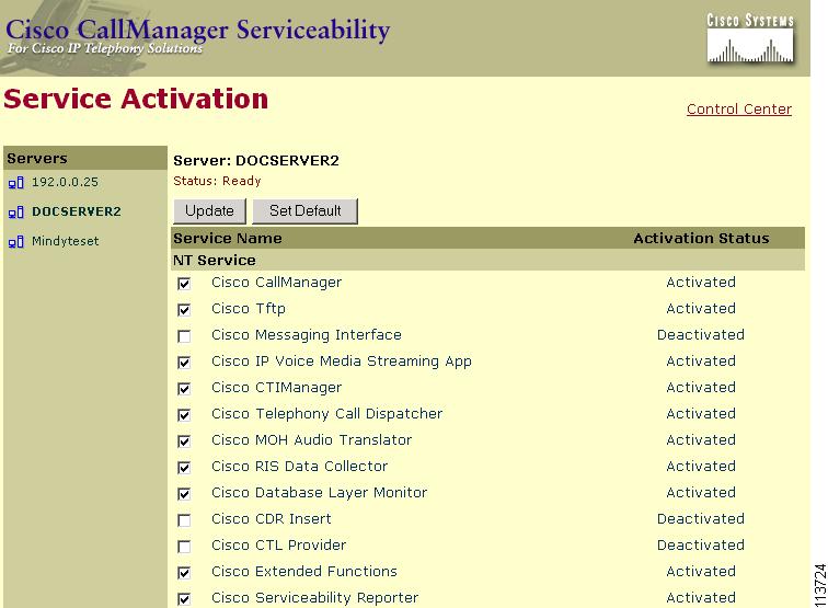
Activating the Cisco Extended Functions Service for QRT
Follow this procedure to activate the Cisco Extended Functions service for use with the QRT feature.
Procedure
Step 1
A list of Cisco CallManager servers displays.
Step 2
Step 3
Step 4
Figure 17-15 shows an example of the Cisco CallManager Serviceability Service Activation window, where you activate the Cisco Extended Functions service.
Figure 17-15 CEF Service Activation
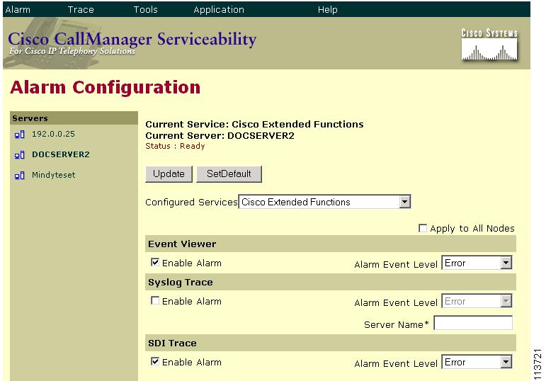
Configuring Alarms and Traces for QRT
Follow this procedure to configure alarms and SDI traces through Cisco CallManager Serviceability.
Procedure
Step 1
A list of Cisco CallManager servers displays.
Step 2
Step 3
Step 4
Figure 17-16 shows an example of the Cisco CallManager Serviceability Alarm Configuration window. (See Figure 17-18 for an example of the logged alarm entry in the Event Viewer.)
Figure 17-16 Alarm Configuration for QRT
Step 5
Step 6
A list of Cisco CallManager servers displays.
Step 7
Step 8
Step 9
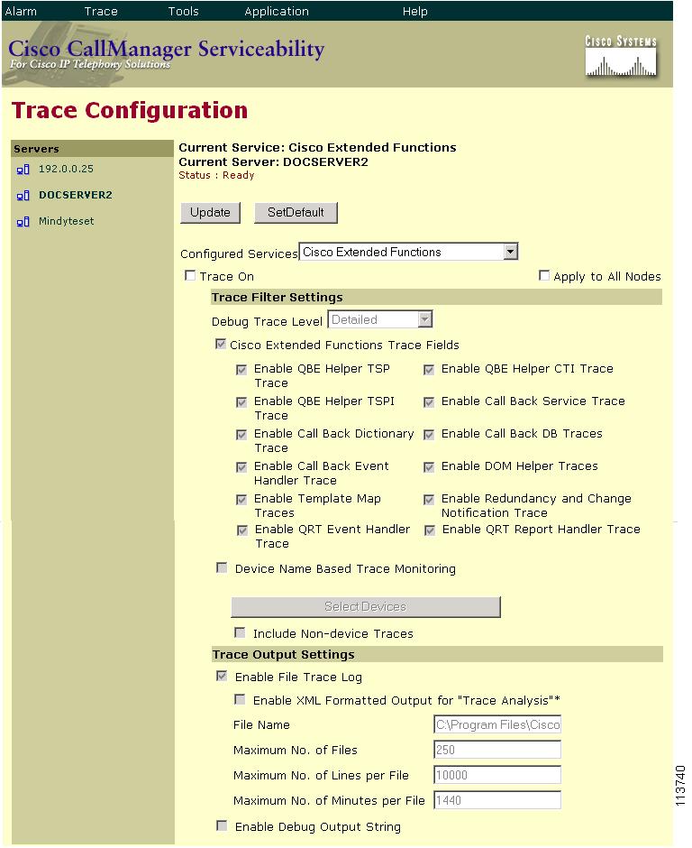
Figure 17-17 shows an example of the Cisco CallManager Serviceability Trace Configuration window, where you configure trace information for the Cisco Extended Functions service and QRT.
Figure 17-17 Trace Configuration for QRT
Step 10
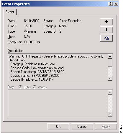
Figure 17-18 shows an example of the Event Properties window of a QRT alarm entry that is logged in the Windows 2000 Event Viewer. This entry shows the following information:
•
•
•
•
•
•
Figure 17-18 Event Viewer - QRT Alarm Entry Event Properties Window
For additional information about configuring alarms and traces, refer to the Cisco CallManager Serviceability Administration Guide.
Setting the Cisco Extended Functions Service Parameters for QRT
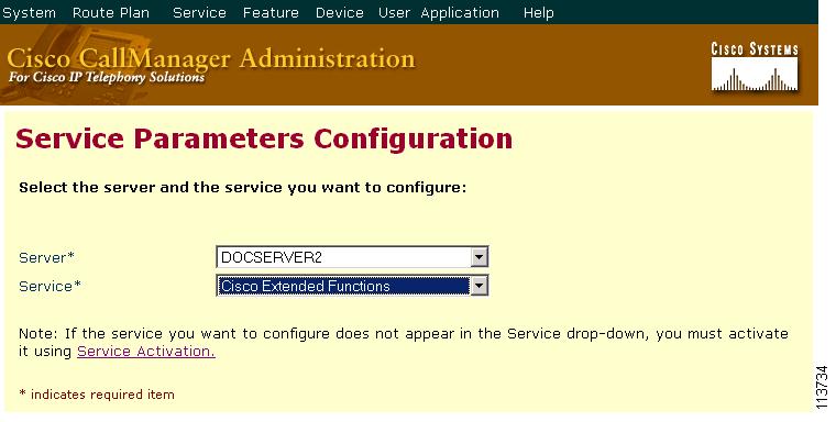
Set the Cisco Extended Functions service parameters by using Cisco CallManager Administration to access the service parameters (Service > Service Parameters). Choose the server where the QRT application resides and then choose the Cisco Extended Functions service.
Figure 17-19 shows an example of the server and service selections in the Cisco CallManager Administration Service Parameters Configuration window.
Figure 17-19 Service Parameters Server Selection
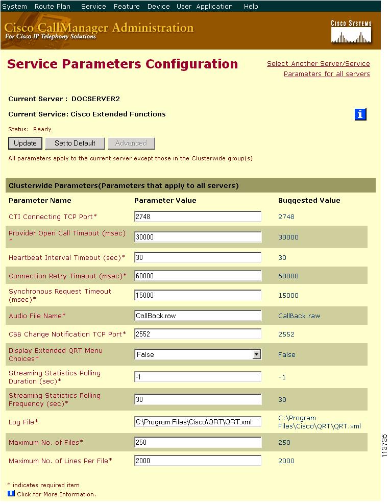
Cisco recommends that you use the default service parameters settings unless the Cisco Technical Assistance Center (TAC) instructs otherwise.
Cisco Extended Functions includes the following parameters for QRT:
•
Recommended default value specifies false (silent mode).
•
Recommended default value specifies -1 (poll until the call ends).
•
Recommended default value specifies 30.
•
Recommended default value specifies
C:\Program Files\Cisco\QRT\QRT.xml.•
Recommended default value specifies 250.
•
Recommended default value specifies 2000.
Figure 17-20 shows an example of the Cisco CallManager Administration Service Parameters Configuration window, where you specify the Cisco Extended Functions service parameters for QRT.
Figure 17-20 Service Parameters Configuration for QRT
Using the QRT Viewer
You can use the QRT Viewer to view the IP phone problem reports that the Quality Report Tool generates. The QRT Viewer allows you to filter, format, and view the tool-generated phone problem reports, so they provide you with the specific information that you need.
Figure 17-21 shows an example of the Cisco CallManager Serviceability Tools window where you access the QRT Viewer.
Figure 17-21 QRT Viewer
Note
QRT Reports
QRT collects information from various sources, such as the source IP phone, the destination IP phone, the Cisco RIS Data Collector, Cisco CallManager, and the user. (The system does not collect information from gateways or other devices.)
The following list provides information about the QRT report fields, segmented by information source:
Information Collected from the Source Device
•
•
•
•
•
•
•
•
•
•
•
Note
Information Collected from the Destination Device
The system collects the following information if the destination device is a supported Cisco IP Phone within same Cisco CallManager cluster. If the destination device is not an IP phone, the information includes only IP address, device name, and device type.
•
•
•
•
•
•
•
•
Note
Information Collected from RIS Data Collector
•
•
•
•
•
•
•
•
•
•
•
•
Information Collected from Cisco CallManager/CTIManager
•
•
•
•
•
•
•
•
Information Collected from the Cisco CallManager Database
•
•
•
Information Collected from the User
•
•
•
Note
Table 17-6 shows the available fields for each supported category.
Providing Information to Users for the QRT Feature
The Cisco IP Phone guides provide procedures for how to use the QRT feature on the Cisco IP Phone. For more information, refer to the following URL for the appropriate Cisco IP Phone Guide for your phone model:
http://www.cisco.com/univercd/cc/td/doc/product/voice/c_ipphon/index.htm.Troubleshooting the QRT Feature
Cisco CallManager Serviceability provides web-based tools to assist in troubleshooting Cisco CallManager problems. Use the Cisco CallManager Serviceability Trace Configuration, Alarm Configuration, and Real-Time Monitoring Tool to help troubleshoot problems with QRT. Refer to the Cisco CallManager Serviceability Administration Guide for more information.
The Trace and Alarm tools work together. You can configure trace and alarm settings for Cisco CallManager services and direct alarms to the Windows 2000 Event Viewer, CiscoWorks2000 Syslog, system diagnostic interface (SDI), or signal distribution layer (SDL) trace log files, or to all destinations.
You can base traces for Cisco CallManager services on debug levels, specific trace fields, and Cisco CallManager devices such as phones or gateways. You can also perform a trace on the alarms that are sent to the SDI or SDL trace log files.
Use the Trace Configuration tool to specify the parameters that you want to trace for troubleshooting Cisco CallManager problems. The Trace Configuration window provides two types of settings: trace filter and trace output. The trace tool provides three main functions:
•
•
•
Use Trace to view the SDI or SDL log files in XML format or use a text editor to view the SDI or SDL log files in text format. (Trace supports text format as well.)
Use the Windows 2000 Event Viewer program to view alarm information that is sent to the Event Log. You can view alarm information that is sent to the SDI or SDL trace log file in text or XML format.
Note
For more information about Cisco CallManager Serviceability tools, refer to the Cisco CallManager Serviceability Administration Guide.
For information about Event Viewer and Microsoft text editors, refer to the Microsoft Windows 2000 documentation.
For information about troubleshooting Cisco CallManager, refer to the Troubleshooting Guide for Cisco CallManager.
Where to Find More Information
Related Topics
•
•
•
•
•
•
Additional Cisco Documentation
•
•
•
•
•
•
•
•