Installation Guide for Cisco Unified Videoconferencing 5100 MCU Release 7.0.1
Bias-Free Language
The documentation set for this product strives to use bias-free language. For the purposes of this documentation set, bias-free is defined as language that does not imply discrimination based on age, disability, gender, racial identity, ethnic identity, sexual orientation, socioeconomic status, and intersectionality. Exceptions may be present in the documentation due to language that is hardcoded in the user interfaces of the product software, language used based on RFP documentation, or language that is used by a referenced third-party product. Learn more about how Cisco is using Inclusive Language.
- Updated:
- December 2, 2009
Chapter: Installing the Cisco Unified Videoconferencing 5100 MCU
Installing the Cisco Unified Videoconferencing 5100 MCU
•![]() Cisco Unified Videoconferencing 5100 Chassis Main Features
Cisco Unified Videoconferencing 5100 Chassis Main Features
•![]() Cisco Unified Videoconferencing 5100 Front and Back Panel Display
Cisco Unified Videoconferencing 5100 Front and Back Panel Display
•![]() How to Perform Initial Cisco Unified Videoconferencing 5100 MCU Configuration
How to Perform Initial Cisco Unified Videoconferencing 5100 MCU Configuration
Cisco Unified Videoconferencing 5100 Chassis Main Features
The Cisco Unified Videoconferencing 5100 chassis is a 1U chassis that contains one Cisco Unified Videoconferencing 5100 MCU.
Cisco Unified Videoconferencing 5100 Front and Back Panel Display
Figure 2-1 Chassis Front Panel
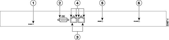
Figure 2-2 Chassis Rear Panel

How to Perform Initial Cisco Unified Videoconferencing 5100 MCU Configuration
•![]() Setting Ethernet Speed and Duplex Parameters
Setting Ethernet Speed and Duplex Parameters
•![]() Initial Configuration and Boot Phases
Initial Configuration and Boot Phases
•![]() Changing the Global User Name and Password
Changing the Global User Name and Password
Setting Ethernet Speed and Duplex Parameters
Use the serial port to set the Ethernet speed and duplex parameters that you want the MCU to use.
Procedure
Step 1 ![]() Access the MCU through the serial port and start the terminal emulator session.
Access the MCU through the serial port and start the terminal emulator session.

Note ![]() If the MCU is already running, you need to reboot or restart the device.
If the MCU is already running, you need to reboot or restart the device.
Step 2 ![]() When the message "Press any key to start configuration" appears on the screen, press any key within 10 seconds.
When the message "Press any key to start configuration" appears on the screen, press any key within 10 seconds.
The network configuration Main menu appears.
Step 3 ![]() Enter A at the prompt to display the Advanced Configuration menu, and press Enter.
Enter A at the prompt to display the Advanced Configuration menu, and press Enter.
The Advanced Configuration menu appears.
Step 4 ![]() Enter 3 at the prompt to select "Change LAN port Settings", and press Enter.
Enter 3 at the prompt to select "Change LAN port Settings", and press Enter.
Step 5 ![]() Enter the appropriate number or letter at the prompt for one of these options:
Enter the appropriate number or letter at the prompt for one of these options:
•![]() 1 - 100Mbps Half Duplex
1 - 100Mbps Half Duplex
•![]() 2 - 100Mbps Full Duplex
2 - 100Mbps Full Duplex
•![]() 3 - Auto Negotiation
3 - Auto Negotiation
•![]() Other - Quit
Other - Quit
Note ![]() We recommend that you select "3 - Auto Negotiation".
We recommend that you select "3 - Auto Negotiation".
Step 6 ![]() Press Enter.
Press Enter.
The network configuration Main menu appears.
Step 7 ![]() Do one of the following:
Do one of the following:
•![]() Enter the letter for the set of parameters that you want to configure.
Enter the letter for the set of parameters that you want to configure.
•![]() Enter Q to save your changes and allow the device to complete the boot process.
Enter Q to save your changes and allow the device to complete the boot process.
Setting the IP Address
You use the serial port on the MCU front panel to assign a new IP address to your MCU. You must assign the IP address before you connect the MCU to the network.
Before You Begin
Gather these items to assign an IP address to the MCU:
•![]() Dedicated IP address for the MCU
Dedicated IP address for the MCU
•![]() Dedicated subnet mask for the MCU
Dedicated subnet mask for the MCU
•![]() IP address of the default router the MCU uses to communicate over the network
IP address of the default router the MCU uses to communicate over the network
•![]() PC with available serial port and terminal emulator software installed
PC with available serial port and terminal emulator software installed
•![]() Serial cable
Serial cable
Procedure
Step 1 ![]() Connect the serial cable from the PC terminal to the serial port on the front panel of theMCU.
Connect the serial cable from the PC terminal to the serial port on the front panel of theMCU.
Step 2 ![]() Connect the power cable.
Connect the power cable.
Step 3 ![]() Start the terminal emulation application on the PC.
Start the terminal emulation application on the PC.
Step 4 ![]() Set the communication settings in the terminal emulation application on the PC as follows:
Set the communication settings in the terminal emulation application on the PC as follows:
•![]() Baud rate: 9600
Baud rate: 9600
•![]() Data bits: 8
Data bits: 8
•![]() Parity: None
Parity: None
•![]() Stop bits: 1
Stop bits: 1
•![]() Flow control: None
Flow control: None
Step 5 ![]() Turn on the power to the MCU.
Turn on the power to the MCU.
A log of the auto-boot events scrolls across the computer monitor.
Step 6 ![]() When the message "Please press Enter to activate this console" appears, press Enter—within a minute. Afterwards, you are prompted with the amount of time that should elapse till the configuration menu starts. (about a minute).
When the message "Please press Enter to activate this console" appears, press Enter—within a minute. Afterwards, you are prompted with the amount of time that should elapse till the configuration menu starts. (about a minute).
The network configuration Main menu appears:
Main menu
N: Configure default network port values
P: Change the configuration software password
S: Configure network security level
T: Configure TFTP servers list
A: Advanced configuration menu
Q: Quit
Step 7 ![]() Enter N at the prompt to configure default network port values and press Enter.
Enter N at the prompt to configure default network port values and press Enter.
Step 8 ![]() Enter 2 to change the network configuration.
Enter 2 to change the network configuration.
Step 9 ![]() Enter the IP address you want to assign to the MCU at the Enter IP address for default interface prompt and press Enter.
Enter the IP address you want to assign to the MCU at the Enter IP address for default interface prompt and press Enter.
Note ![]() Do not use leading zeros in the IP address.
Do not use leading zeros in the IP address.
Step 10 ![]() Enter the IP address of the router associated with the segment in which the unit will be installed at the Enter Default Router IP Address prompt and press Enter.
Enter the IP address of the router associated with the segment in which the unit will be installed at the Enter Default Router IP Address prompt and press Enter.
Note ![]() Do not use leading zeros in the IP address.
Do not use leading zeros in the IP address.
Step 11 ![]() Enter the subnet mask without leading zeros at the Enter IP Mask for default device prompt and then press Enter.
Enter the subnet mask without leading zeros at the Enter IP Mask for default device prompt and then press Enter.
To use the default mask of 255.255.0.0, press Enter.
Step 12 ![]() Press Enter in the next prompts.
Press Enter in the next prompts.
Step 13 ![]() Press Y to save the new configuration.
Press Y to save the new configuration.
Step 14 ![]() Press Q to quit the configuration menu.
Press Q to quit the configuration menu.
Step 15 ![]() Allow the unit to complete the reboot process. A new emulator session begins.
Allow the unit to complete the reboot process. A new emulator session begins.
Step 16 ![]() Close the terminal emulator session.
Close the terminal emulator session.
Initial Configuration and Boot Phases
Initial monitoring and administration of the MCU are performed from a remote PC through a serial connection using a terminal emulation application, such as HyperTerminal. This allows you to access the boot configuration menu of the MCU. At power-up, the MCU goes through a boot phase in which the embedded operating system initializes and displays basic information. The first time you install the MCU, you assign an IP address to the MCU using a terminal cable connection to access the boot configuration menu.
Note ![]() You can perform serial port configuration of the MCU only at startup, if you choose to enter the configuration menu—within a minute—when indicated.
You can perform serial port configuration of the MCU only at startup, if you choose to enter the configuration menu—within a minute—when indicated.
Once the boot phase is complete, the only way you can access the configuration menu is by restarting the MCU.
You use the serial port on the MCU front panel to assign a new IP address to your MCU. You must assign the IP address before you can connect the MCU to the network.
Changing the Global User Name and Password
You can change the global user name and password that the MCU uses. You use this user name and password to access the configuration web page for the MCU. The user name and password are required for these tasks:
•![]() Starting a Telnet session to monitor the MCU
Starting a Telnet session to monitor the MCU
•![]() Upgrading the MCU software
Upgrading the MCU software
•![]() Uploading Interactive Voice Response (IVR) messages to MCU configuration memory
Uploading Interactive Voice Response (IVR) messages to MCU configuration memory
The default global user name is admin. The default password is password.
Procedure
Step 1 ![]() Start a terminal emulator session as described in the Setting the IP Address.
Start a terminal emulator session as described in the Setting the IP Address.
Step 2 ![]() Enter P at the prompt.
Enter P at the prompt.
Step 3 ![]() Enter the name that you want to use as the global user name at the Enter User name prompt, and press Enter.
Enter the name that you want to use as the global user name at the Enter User name prompt, and press Enter.
Step 4 ![]() Enter the password that you want to use at the Password prompt, and press Enter.
Enter the password that you want to use at the Password prompt, and press Enter.
The network configuration Main menu appears.
Step 5 ![]() Do one of the following:
Do one of the following:
•![]() Enter the letter for the set of parameters that you want to configure.
Enter the letter for the set of parameters that you want to configure.
•![]() Enter Q to save your changes and allow the device to complete the boot process.
Enter Q to save your changes and allow the device to complete the boot process.
Accessing the MCU Interface
Procedure
Step 1 ![]() Launch your browser and enter the IP address or the name of the MCU followed.
Launch your browser and enter the IP address or the name of the MCU followed.
Step 2 ![]() Enter the Administrator user name and password in the appropriate fields and select Go.
Enter the Administrator user name and password in the appropriate fields and select Go.
The default global user name is admin. The default password is password.
Note ![]() If you try to sign in as an Administrator and another Administrator is currently signed in, the MCU signs you in as a Read only user. The words "Read Only" appear at the top of the window and a pop-up displays the IP address of the Administrator already signed in. Read only users cannot edit MCU settings.
If you try to sign in as an Administrator and another Administrator is currently signed in, the MCU signs you in as a Read only user. The words "Read Only" appear at the top of the window and a pop-up displays the IP address of the Administrator already signed in. Read only users cannot edit MCU settings.
 Feedback