-
Cisco CDA Visual Quality Experience Application User Guide, Release 3.1
-
Preface
-
Chapter 1: Introduction to Cisco CDA Visual Quality Experience Application
-
Chapter 2: Getting Started with the VQE Startup Configuration Utility
-
Chapter 3: Using the VQE Channel Provisioning Tool
-
Chapter 4: Using the VQE-S Application Monitoring Tool
-
Chapter 5: Troubleshooting VQE Software Components
-
Chapter 6: Configuring VQE Server and VQE Tools
-
Appendix A: VQE, System, and Network Parameters
-
Appendix B: Using Net-SNMP
-
Appendix C: VQE System Messages
-
Appendix D: Manual Initial VQE System Configuration
-
Appendix E: Configuring DHCP and DNS Servers for VCDS
-
Appendix F: Changing the Boot Sequence to Start from the CD/DVD Drive
-
 Feedback
Table Of Contents
Introduction to Cisco CDA
Visual Quality Experience ApplicationLookaside Mode and the Cisco CDE110
VQE-S and VQE-C Support for All NAT Mapping Types
VQE-C Forward Error Correction
VQE-C IPTV Packet Loss Monitoring
VQE-C Software Development Kit and Documentation
VQE Deployment Options and Requirements
VQE Reference Architecture Model
Cisco End-to-End IPTV Solution Model
VQE Channel Provisioning Tool and Channel Information
VQE-S Application Monitoring Tool
VQE-S RTCP Exporter for Video-Quality Monitoring
Introduction to Cisco CDA
Visual Quality Experience Application
This chapter provides information on Cisco CDA Visual Quality Experience Application (VQE), Release 3.1, and contains the following major topics:
•
VQE Deployment Options and Requirements
•
•
•
VQE Overview
This VQE overview has the following sections:
•
•
Introduction to VQE
Cisco CDA Visual Quality Experience Application (VQE) offers service providers a set of technologies and products associated with the delivery of IPTV video services. VQE is designed to improve the quality of IPTV services and subscribers' viewing experiences. VQE is part of a Cisco end-to-end solution that builds video awareness into the network infrastructure. For Cisco VQE, Release 3.1, VQE technology is intended for wireline operators who offer managed broadcast (multicast) IPTV services using xDSL.
IPTV subscribers expect high video quality. Because many subscribers are migrating from existing analog or digital cable services, their quality expectation has already been set. To attract subscribers, IPTV providers must meet or exceed the video experience of existing services. VQE technology and products provide that capability.
Video is less tolerant of network factors such as jitter, delay, and especially packet loss because a single IP packet carries up to seven MPEG transport frames. Therefore, IP networks require additional functionality to deliver the video quality expected by subscribers. The accepted industry benchmark for quality is to deliver a maximum of one video "artifact" or perceived distortion during the viewing of a one-hour movie. This level of quality translates into a network-layer requirement of less than 7.8E-7 video packets loss. Most xDSL networks are not optimized to deliver such low levels of packet loss.
A second issue that affects IPTV video quality is channel change time (CCT). Consumers have become used to the current CCT—which is less than two seconds—offered by digital cable and digital satellite services. A number of factors can contribute to longer IPTV channel change times, including Internet Group Management Protocol (IGMP) delays, MPEG decoding delays, and I-frame acquisition time. Non-optimized IPTV channel change times can take several seconds. Channel change times as long as five seconds have been observed.
VQE addresses the issue of video quality from both a network infrastructure and a video technology perspective. VQE provides the linkage to optimize video delivery over next-generation carrier networks. Based on industry standards, including Real-Time Transport Protocol (RTP) and RTP Control Protocol (RTCP), Cisco VQE, Release 3.1, provides these mechanisms to help in delivering entertainment-grade services to subscribers:
•
•
•
•
The two error-repair options, Unicast Retransmission and FEC, can be used separately or together for Hybrid Error Repair. Each repair mechanism has its own advantages and limitations. Whether Unicast Retransmission or FEC or both are used, the subscriber does not detect the error repair and no video artifact results.
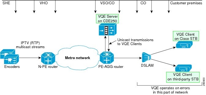
Figure 1-1 shows the location of the major network and VQE components in the service-provider network and in the subscriber's customer premises equipment (CPE).
Figure 1-1 VQE Major Components
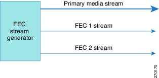
If FEC is used for error repair, an SMPTE 2022 compatible FEC stream generator, such as the Cisco Digital Content Manager (DCM), is required. The FEC stream generator (shown in Figure 1-3) is often located in the headend and transmits application-layer FEC packets. Real-Time Transport Protocol (RTP) encapsulation is a prerequisite for FEC.
The FEC stream generator, which is connected to the real-time encoders, subscribes to video channels from the headend and encodes FEC for each channel. It is responsible for originating FEC packets associated with individual channels and with primary multicast streams. For each FEC-enabled channel, a primary media stream and two encoded FEC streams are sent over multicast addresses (Figure 1-2).
Figure 1-2 FEC Stream Generator
VQE Major Software Components
The two major VQE software components that implement Unicast Retransmission, FEC, Rapid Channel Change, and IPTV Packet Loss Monitoring are:
•
–
–
•
–
–
With both Unicast Retransmission and FEC, the missing packets are resequenced by the set-top box without interruption.
VQE Client is available with certain Cisco set-top boxes running Scientific-Atlanta IPTV Layer (SAIL) 1.x and 2.x. Please contact your Cisco sales representative for further information. VQE Client can also be integrated into set-top boxes from third-party vendors. The VQE Client code and Software Development Kit (SDK) is available to third-party vendors through an open-source program.
VQE Hybrid Error Repair
VQE Hybrid Error Repair occurs when Unicast Retransmission and FEC are used together. The devices used for Hybrid Error Repair are shown in Figure 1-3, which for simplicity omits some of the network elements. Hybrid Error Repair allows the service provider to customize VQE error repair to match the error characteristics of a given access network.
Figure 1-3 Hybrid Error Repair
In an IPTV system, video data is very sensitive to packet losses due to the interdependence of encoded data. One packet loss could cause quality degradation of several successive frames in a group of pictures (GOP). Selective retransmission and FEC are two methods to protect channels from packet losses.
With selective retransmission (Unicast Retransmission), NACK packets are sent to VQE Server to request retransmission of the lost packets whenever the receiver (VQE Client) detects dropped packets. Selective retransmission is very efficient in terms of bandwidth utilization in a unicast scenario, but may flood the network with control packets when errors are highly correlated in nature.
The application-layer FEC method of error repair is usually used for controlling errors in a one-way communication system. The FEC stream generator (for example, the Cisco DCM) sends FEC information along with the primary media stream. VQE Client uses the FEC data to detect and correct the lost packets. No feedback to VQE Server is needed. FEC is optimized for non-bursty (short burst, correlated errors. Unicast Retransmission is better for bursty, uncorrelated errors.
In addition to providing a flexible solution for error repair, VQE Hybrid Error Repair is also able to correct more lost-packet errors than when FEC is used alone. If VQE Client tries but is unable to retrieve lost packets using FEC, it can request that VQE Server selectively retransmit the dropped packets.
The VQE Hybrid Error Repair solution provides the flexibility to customize an error-repair scheme that best suits the network error characteristics and available access-link bandwidth.
VQE Rapid Channel Change
Channel change time is defined as the time from when a subscriber initiates a channel change to the time the video for the new channel is displayed. The Rapid Channel Change (RCC) functionality built into VQE Server and VQE Client reduces channel change time from several seconds to approximately one second.
There are several factors that contribute to channel change time:
•
•
–
–
–
–
–
•
Not all of the above factors need to be addressed by RCC functionality. For example, many Digital Subscriber Line Access Multiplexers (DSLAMs) can provide fast leave for IGMP, which addresses the multicast leave latency factor.
The goal of RCC is to reduce or eliminate the main sources of channel change delay. With RCC, the resulting channel-change delay should be similar to or better than the delay observed in a typical digital broadcast.
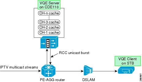
For RCC, VQE Server caches multicast IPTV packets corresponding to each channel (Figure 1-4). Each cache holds a few GOPs of video data as well as PAT, PMT, ECM, PCR, and sequence information.
When the subscriber requests a channel change, VQE Client on the set-top box requests the IPTV packets for the new channel from its target VQE Server, using a specific RTCP message. After it has sent the RTCP message, the VQE Client issues an IGMP join for the new channel at an optimum point in time.
Figure 1-4 VQE Server Caches Multicast IPTV Packets for Rapid Channel Change
Upon receipt of the request, the VQE Server locates the appropriate channel cache, identifies the location of the IPTV packet carrying the beginning of a recent I-frame, and transmits a short unicast burst of packets starting with the I-frame to the requesting VQE Client.
Prior to sending the unicast burst, the VQE Server originates an RTCP message to the requesting VQE Client "priming" it with video parameters such as PAT, PMT, and ECM.
Because the incoming burst from the VQE Server contains an I-frame, the set-top box decoder can immediately start processing the MPEG information. This greatly reduces the time a subscriber waits before the image is rendered on the TV screen.
After a short period of time, multicast packets for the new channel start to arrive at the set-top box. The VQE Client monitors RTP sequence numbers from both unicast and multicast streams. It is likely that VQE Client will see a few packets with duplicate RTP sequence numbers before the unicast stream ends. During this period, the VQE Client will only forward one copy of the RTP packet to the MPEG demultiplexing stage.
The VQE Client is responsible for managing the seamless transition between unicast and multicast IPTV packets. The RCC unicast burst continues for up to the full duration of the IGMP join or until it is explicitly stopped by a message sent from the VQE Client to the VQE Server.
RTP and RTCP
VQE relies on Real-Time Transport Protocol (RTP) and RTP Control Protocol (RTCP). RTP is used to carry video packets over multicast streams from the video headend to the VQE Clients on the set-top boxes. It is also used to transport specific video packets between the VQE Server and a VQE Client. RTCP is a signaling protocol used between VQE devices. RTP is the transport baseline for application-layer FEC, Unicast Retransmission, and Rapid Channel Change.
RTP encapsulation is typically the responsibility of real-time encoders and specialized video products, such as a Cisco DCM. These devices often reside in the video headend office (VHO) or super headend (SHE). RTP sequence numbers are assigned to IPTV packets and are unique within a given multicast group or channel.
A growing number of real-time encoders support native RTP and SMPTE 2022 FEC. For those that support UDP only or RTP encapsulation, the Cisco DCM product is recommended. For FEC support, the DCM requires the GbE I/O Board with a FEC daughter card, and DCM software version 5 or higher.
VQE Web Browser-based Tools
VQE also provides two web browser-based tools: VQE Channel Provisioning Tool (VCPT) and VQE-S Application Monitoring Tool (AMT).
•
•
VQE Server and VQE Channel Provisioning Tool are bundled software and hardware solutions. VQE Server and VQE Channel Provisioning Tool run on separate Cisco Content Delivery Engine 110 (CDE110) appliances. A typical network might consist of multiple CDE110s hosting VQE Server and one or two CDE110s hosting VQE Channel Provisioning Tool and VQE Client Channel Configuration Delivery Server.
Lookaside Mode and the Cisco CDE110
The VQE-S software functions in lookaside mode where the VQE Server is not directly in the video data path. Lookaside mode has these advantages:
•
•
•
The Cisco Content Delivery Engine 110 is a standalone, carrier-hardened appliance running the Linux operating system. The Cisco CDE110 is NEBS-compliant and suitable for central office lights-out locations. The Cisco CDE110 comes with the required software pre-installed: VQE Server or VQE Channel Provisioning Tool, Linux, Apache web server, and other software.
VQE Benefits
Cisco VQE, Release 3.1, provides the following benefits to the service provider:
•
•
•
•
•
•
•
•
•
•
•
Cisco VQE also provides the subscriber with an enhanced video experience with higher and consistent visual and audio quality. Subscribers with noisier transmission lines or longer loop lengths can take advantage of the service provider's video offerings, bundles, and unique content.
VQE Server
The VQE Server (VQE-S) software is hosted on a Cisco CDE110 appliance running a standard Linux operating system. The Cisco CDE110 comes with the required software pre-installed: VQE-S, VQE-S Application Monitoring Tool, Linux, Apache web server, and other software.
VQE-S is responsible for the following functions:
•
•
•
•
•
•
•
Like a regular IP host, VQE-S joins multicast groups using Internet Group Management Protocol (IGMP). VQE-S maintains a dedicated buffer for each channel. VQE-S receives the multicast stream for each channel from upstream, caching a few seconds of the most recently received program content from each. VQE-S can use the same cache of video to service both Unicast Retransmission requests and Rapid Channel Change requests.
For Unicast Retransmission, when a VQE Client requests retransmission of missing packets, VQE-S locates them in its cache and, if found, delivers them to the set-top box through an associated RTP retransmission stream. A single VQE Server can process up to 10,000 inbound repair requests per second. A repair request may support up to 17 packet retransmissions in a single transaction.
A number of factors affect how many errors a single VQE Server can repair for a single VQE Client. These factors include the distribution of errors, the bandwidth of the channel, and the size of the jitter buffer in the set-top box. The VQE-S software includes global and per-client policers to provide sensible rate limits for the traffic associated with Unicast Retransmission.
For Rapid Channel Change, VQE Server uses much the same infrastructure as Unicast Retransmission with some major additions. VQE-S can use the same cache of video data for both Unicast Retransmission and Rapid Channel Change. Instead of requesting repair of a specific packet, the VQE Client sends VQE-S an RTCP messages requesting a unicast burst of IPTV packets for a new channel.
In addition, VQE-S uses its MPEG Parser component to choose the start point of the RCC burst for the new channel. To properly form the RCC burst, the MPEG Parser examines the video data for several pieces of crucial information, caches the information, and provides it to other VQE-S components upon receipt of an RCC request. Before play-out can begin, VQE Client must receive this information (for example, PAT, PMT, and PCR) to properly display the video. This additional data is sent out of band of the RCC burst and is used to prime the MPEG decoder on the client side.
VQE Server supports setting Differentiated Services Code Point (DSCP) values on IPTV-related packets so that specific levels of service can be assigned to different types packets. The service provider can configure DSCP values with the VQE Configuration Tool for RTCP and RTP traffic types.
The number of channels supported by single VQE Server is determined by the ingest capacity of the CDE110 server. Currently, the CDE110 provides 1 Gbps of ingest bandwidth. In practical terms, the number of channels currently supported by a single VQE Server is, for example, approximately 500 channels at 2 Mbs each, or 250 channels at 4 Mbs each.
VQE-S High Availability
VQE-S provides a number of high-availability mechanisms for resiliency and redundancy:
•
•
•
•
For Multicast Load Balancing, when a multicast stream used for caching on the VQE-S host starts or stops, VQE-S determines the best Cisco CDE110 Ethernet interface on which to join or leave the multicast group. The VQE-S software distributes the joins across available Ethernet interfaces to avoid oversubscription. VQE-S also monitors the status of these interfaces, moving the streams to other interfaces in case of interface failure.
VQE-S uses Linux system and network services for system initialization, network access, interface status monitoring, and multicast stream reception.
VQE-S and VQE-C Support for All NAT Mapping Types
VQE supports all Network Address Translation (NAT) mapping types, including address and port-dependent mapping (symmetric NAT). Symmetric NAT is the most restrictive form of NAT behavior.
Deployments where a CPE device is behind a NAT device require a NAT transversal mechanism, such as a Simple Traversal of UDP (User Data Protocol) through NATs (STUN) Server. The STUN Server is included with the VQE-S software, and a STUN Client is included with VQE-C. When VQE-C tunes to a new channel, it sends STUN binding requests to the STUN Server on the VQE-S host. VQE-C sends the requests to the channel's feedback target IP address and RTP/RTCP retransmission ports as configured on the VQE Server. VQE-C uses the STUN Server responses to determine whether it is behind a NAT device and what type of NAT device it is.
VQE-C is optimized to handle a variety of NAT configurations. For example, if VQE-C determines from the initial STUN responses that it is not behind a NAT device, it turns off NAT mode so that VQE-C does not send further STUN messages.
The STUN Server that is included with VQE-S can be turned on or off using a configurable option in the VQE-S configuration file. Unless it is certain that no set-top boxes being serviced by VQE-S are behind a NAT device, Cisco recommends that you enable the STUN Server. For information on enabling the STUN Server, see the "VQE STUN Server Is Enabled By Default" section on page D-14.
VQE Client
The VQE Client (VQE-C) software runs on customer premises equipment (CPE), such as a set-top box. VQE Client supports Unicast Retransmission, FEC, Rapid Channel Change, and video-quality statistics by providing the following:
•
•
•
•
•
For Unicast Retransmission, if an error in video transmission occurs, the VQE-C software detects the packet loss and requests a retransmission while holding the video sequence in queue. VQE Server automatically repairs the error by transmitting the missing packet, which is resequenced by the set-top box without interruption. The entire error-repair cycle is imperceptible to the viewer.
For Rapid Channel Change, when a subscriber selects a new channel, VQE-C sends to the VQE Server a special RTCP packet requesting a unicast burst of the IPTV packets for the new channel. As soon as the unicast IPTV packets arrive, the VQE-C software is responsible for sending the packets to the decoder. When the multicast IPTV packets for the new channel begin to arrive, VQE-C manages the seamless transition between unicast packets from VQE Server and multicast packets from the headend encoder.
VQE Clients can get channel configuration information from a VQE Client Channel Configuration Delivery Server or from a centralized network management/configuration server that supports the DESCRIBE request of the RTSP protocol. For information on the interactions between a VQE Client and a VQE Client Channel Configuration Delivery Server, see the "VQE Channel Provisioning Tool and Channel Information" section.
VQE Client supports setting Differentiated Services Code Point (DSCP) values on IPTV-related packets it sends so that specific levels of service can be assigned to packets. DSCP values can be configured with the rtcp_dscp_value parameter in the VQE-C system configuration file. The setting of rtcp_dscp_value applies to both the RTCP messages and the STUN messages.
VQE Client is available in two deployment models:
•
•
For information on VQE-C deployment models, see the "VQE Deployment Options and Requirements" section.
VQE-C Forward Error Correction
VQE Client supports both one-dimension FEC (one FEC stream) and two-dimension FEC streams (two FEC streams). The Cisco DCM or other SMPTE 2022 compliant FEC stream generator sends one primary media stream and one or two FEC streams over different UDP ports to VQE-C. The VQE-C receives and processes these FEC streams to provide packet-level error repair.
Before receiving the FEC packets, the VQE-C must learn some basic information about the FEC session, such as the IP address and port numbers of FEC streams. This information is obtained through the channel configuration file that is sent to the VQE-C from the channel provisioning server, such as VQE Client Channel Configuration Delivery Server. The FEC streams are configured on a per-channel basis.
When a VQE Client detects packet loss on a channel that is configured for FEC and Unicast Retransmission, the following occurs:
•
•
The use of one-dimension (1-D) or two-dimension (2-D) FEC is configured when the channel is defined. 1-D FEC uses one FEC stream, and 2-D FEC uses two FEC streams. While 2-D FEC can correct more packet losses than 1-D FEC, 2-D FEC sometimes requires more intensive processing of both FEC streams to maximize the number of packets recovered. FEC bandwidth overheads may be too high in some deployments for full FEC-based error repair deployment. FEC can be turned on or off on a per-channel basis through the VQE-C channel configuration file.
VQE-C supports a number of extensions to the SMPTE 2022 standard. VQE-C autodetects L (column) and D (row) values, and allows any combination of L and D sizes where L*D <= 256. This is an extension of the SMPTE 2022 limit of L*D <= 100. VQE-C also allows any payload value to identify FEC packets where the standard says the value must be equal to 96.
VQE-C supports SMPTE 2022 Annex A and Annex B stream orderings. For detailed information on 1-D and 2-D FEC, see the SMPTE standard Forward Error Correction for Real-Time Video/Audio Transport Over IP Networks (SMPTE 2022-1-2007). The standard is available for purchase at this URL:
http://www.smpte.org/standards
VQE-C IPTV Packet Loss Monitoring
When used with VQE-S RTCP Exporter, the VQE-C software also provides the instrumentation for IPTV Packet Loss Monitoring and valuable "last hop" analysis. VQE Clients generate RTP packet-level statistics for packet loss, jitter, delay, and other quality measurements. VQE Clients provide statistics on both Unicast Retransmission and FEC. For the RTCP reports, VQE Clients transmit RTCP compound packets to their target VQE-S. Each compound packet contains an RTCP receiver report as well as other information.
For more information on IPTV Packet Loss Monitoring, see the "VQE-S RTCP Exporter for Video-Quality Monitoring" section.
VQE-C Software Development Kit and Documentation
VQE-C consists of a software development kit (SDK), which can be used for VQE-C integration into set-top boxes from third-party vendors. The VQE-C code and SDK is available to third-party vendors through an open-source program. The VQE-C code resembles a standard Linux software component. The VQE-C source code is currently supported for the Linux operating system. For information on support for other operating systems, contact your Cisco account representative.
The VQE-C library provides a set of high-level APIs designed to support easy integration into an existing set-top box (STB) software base. The programmatic interface provides a "socket replacement" interface, which is used to get packets from a repaired VQE Server-enhanced video stream. VQE-C also provides APIs for updating its channel configuration data and acquiring statistics on error repairs.
The integrator configures the VQE-C through system configuration file parameters. The parameters allow customizing of many elements of the VQE-C system (for example, number concurrent streams and client policing). The configuration of a VQE Client must be coordinated with the configuration of VQE Server. Certain features are operational only when they are enabled on both VQE-C and VQE-S.
The VQE-C command-line interface (CLI), based on the open source library libcli (http://sourceforge.net/projects/libcli), is designed primarily for testing and debugging the VQE-C software on the set-top box. The scope of the CLI is limited to the VQE-C software only. The CLI is accessible by telnet.
The VQE-C SDK and documentation can be downloaded from Cisco.com. Table 1-1 lists the VQE-C documentation that is provided.
VQE Deployment Options and Requirements
The two basic deployment options for VQE are as follows:
•
•
With both deployment options, VQE Server is deployed on a Cisco CDE110 appliance running Linux.
VQE Reference Architecture Model
The VQE reference architecture model is designed for existing IPTV deployments or new IPTV deployments that do not use Cisco set-top boxes. Cisco offers VQE-C as open-source software. VQE-C is implemented so that service providers and CPE device vendors can integrate the VQE-C software with third-party set-top boxes. Appropriate development-level documentation is available along with the VQE-C code.
With this model, the service provider uses the VQE Channel Provisioning Tool to define channels and servers and to create channel lineups for different subscriber regions. The VQE Channel Provisioning Tool sends the channel information to the VQE Servers and to the VQE Client Channel Configuration Delivery Servers from which each VQE Client gets its channel information. The channel information is in the Session Description Protocol (SDP) format required by VQE-S and VQE Client Channel Configuration Delivery Server.
Cisco End-to-End IPTV Solution Model
The Cisco end-to-end IPTV solution model is designed for new or "greenfield" IPTV opportunities. VQE technology is included as an integral part of the Cisco end-to-end video solution.
In this model, VQE-C is integrated with selected Cisco set-top boxes. The main difference between the Cisco end-to-end IPTV solution and the VQE reference architecture models lies with the integration responsibility of VQE-C.
•
•
For the Cisco end-to-end IPTV solution, contact your Cisco representative for details of the set-top box models and software versions supported.
VQE Deployment Requirements
To deploy VQE, the following prerequisites must be met:
•
•
•
•
•
•
•
VQE Channel Provisioning Tool and Channel Information
The VQE Channel Provisioning Tool (VCPT) is responsible for the creation, maintenance, and distribution of the channel information containing channel-lineup data. VCPT includes a browser-based GUI that allows the service provider to provision the following:
•
•
•
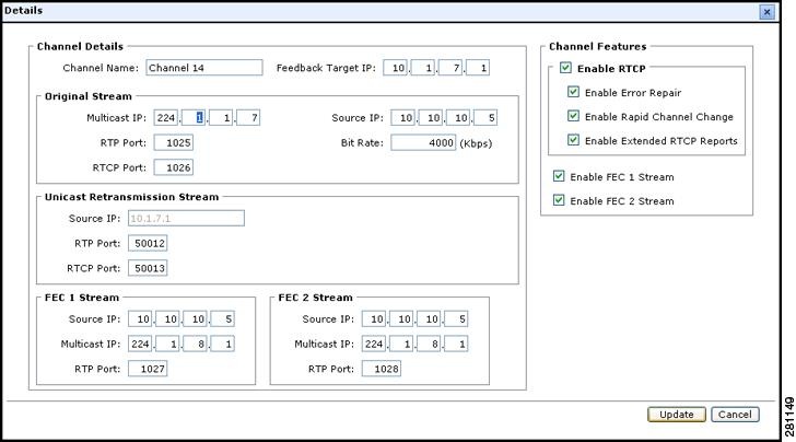
Figure 1-5 shows the details that the service provider defines for each channel using VCPT. The channel details include information that is used for VQE error repair—both Unicast Retransmission and FEC—and for Rapid Channel Change.
Figure 1-5 VCPT Channel Definition
The VCPT GUI has a clone capability to simplify and expedite channel information. When the service provider uses VCPT to define the set of VQE Servers that receive the channel information, the VQE Servers can be grouped based on channel lineups. Using separate VCPT configuration files makes it possible to manage multiple deployments. For example, one VCPT configuration file might be for the channel lineup in one metro region, and another VCPT configuration file might be for the channel lineup in another metro region.
The VCPT channel-provisioning process creates a persistent local database, which is stored on the Cisco CDE110 appliance. When the Cisco CDE110 or VCPT is restarted, channel data and server grouping information is read from the local database.
When the user completes channel, server, and channel-lineup configuration and initiates the VCPT send operation, VCPT sends the channel information in Session Description Protocol (SDP) format to the set of VQE Servers and to the VQE Client Channel Configuration Delivery Server.
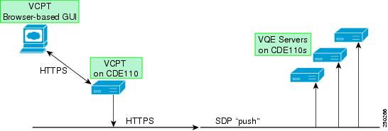
VCPT sends or "pushes" the channel information to all VQE Servers that are defined in the current VCPT configuration file. The channel information is sent to the VQE Servers over secure HTTPS. VCPT contains a secure HTTPS client, and each VQE Server has an embedded web server running. Each VQE Server stores it own local copy of the channel information. Figure 1-6 shows the interactions between VCPT and the VQE Servers. For information on the VQE Servers, see the "VQE Server" section.
Figure 1-6 VCPT: Sending Channel Information to VQE Servers
VQE Client Channel Configuration Delivery Server (VCDS) is a software component installed on the Cisco CDE110 that hosts VCPT. When the user initiates the VCPT send operation, VCPT "pushes" the channel information to the VQE Client Channel Configuration Delivery Servers. VCPT sends the channel information in SDP format through HTTPS similar to the way it is sent to the VQE Servers.
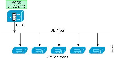
Each VQE Client running in a CPE device, such as a set-top box, uses a Real Time Streaming Protocol (RTSP) "pull" operation to receive the channel information. The VQE Client learns the name of the VQE Client Channel Configuration Delivery Server through a Domain Name System (DNS) server. After the VQE Client learns the VQE Client Channel Configuration Delivery Server name, it sends out an RTSP DESCRIBE request, asking for information on channels. The VQE Client Channel Configuration Delivery Server sends the channel configuration data for the entire channel set in SDP format. Figure 1-7 shows the interaction between a VQE Client Channel Configuration Delivery Server (VCDS) and the VQE Clients on the subscriber set-top boxes.
Figure 1-7 VQE-C on Set-Top Box: Receiving Channel Information from VCDS
For information on the interactions between the VQE Client Channel Configuration Delivery Server (VCDS) and the other components in the channel delivery infrastructure, see Appendix E, "Configuring DHCP and DNS Servers for VCDS."
VQE-S Application Monitoring Tool
The VQE-S Application Monitoring Tool (VQE-S AMT or AMT) is a browser-based GUI that allows the service-provider operator to do the following:
•
•
•
•
•
–
–
•
The next paragraphs provide a few examples of VQE-S AMT functionality.
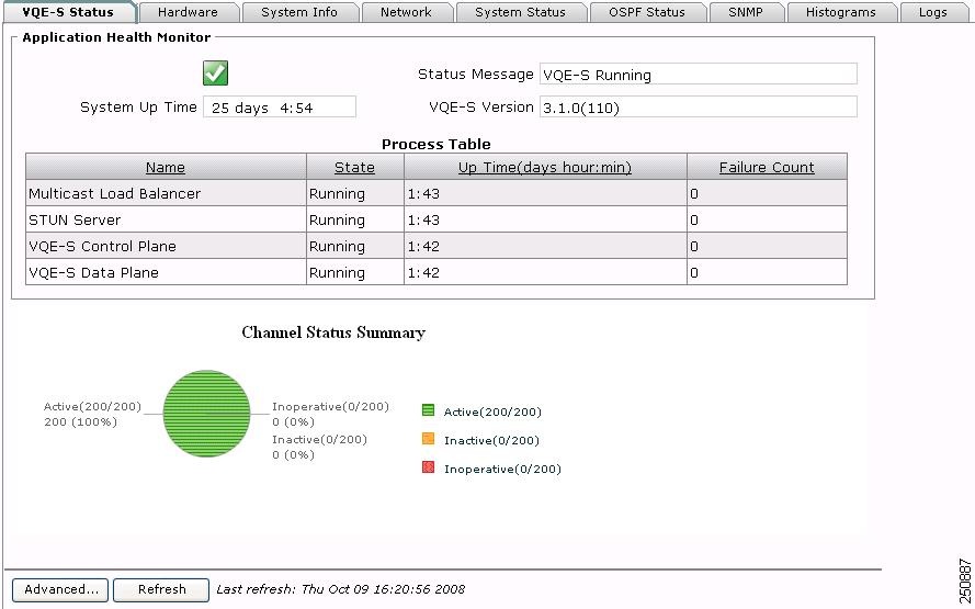
When you log in to VQE-S AMT, the initial window (Figure 1-8) shows the health of VQE-S processes and other status information.
Figure 1-8 Monitoring VQE-S Processes
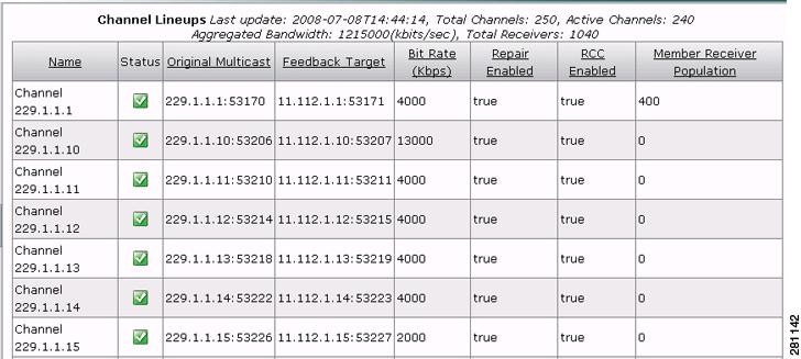
With VQE-S AMT, you can view the channel lineup that was sent from the VQE Channel Provisioning Tool. Figure 1-9 shows a partial example of the channel lineup with usage statistics that VQE-S AMT displays.
Figure 1-9 Viewing Channel Lineups with Usage Statistics
In Figure 1-9, the channel-lineup summary data indicates when the lineup was last updated (for example, with VCPT) and provides totals for all channels and active channels as well as aggregated bandwidth and total receivers:
 Last update: 2008-07-08T14:44:14, Total Channels: 250, Active Channels: 240
Aggregated Bandwidth: 1215000 (kbits/sec), Total Receivers: 1040
In the channel-lineup summary data, the rightmost column, Member Receiver Population, is the number of VQE Clients that are currently receiving this multicast stream.
VQE-S AMT uses the Unicast Retransmission and Rapid Channel Change counters kept by the VQE Server to display a variety of data. For Unicast Retransmissions, the counters include NACK messages received from VQE Clients, RTP packets requested and sent, and error repair rates. For Rapid Channel Change, the counters are for RCCs requested, accepted, and refused.
For Cisco VQE AMT provides limited configuration capabilities. The items that can be configured with AMT include parameters for the following:
•
•
The VQE Server channel lineup is stored locally on the Cisco CDE110 appliance. If VQE-S is restarted, the channel lineup is read from the local repository. The VQE-S counters for statistics that AMT displays are reset to zero when VQE-S is restarted.
VQE-S AMT is a web application that uses the application server and web server that are pre-installed on the Cisco CDE110 where VQE-S runs. VQE-S AMT has an XML-RPC client that communicates with multiple internal applications, such as VQE-S processes, to send and receive application management data.
VQE-S RTCP Exporter for Video-Quality Monitoring
VQE-S provides a variety of data for monitoring IPTV packet delivery and for fault isolation. VQE-S receives RTCP reports from VQE Clients on the CPE devices and from reports generated by the VQE-S itself. In those reports, VQE Clients provide statistics for RTP packet loss, jitter, delay, and other quality measurements. VQE Clients also provide statistics on Unicast Retransmission.
For the RTCP reports, each VQE Client periodically transmits RTCP compound packets to its target VQE-S. Each compound packet contains an RTCP receiver report as well as other information. Each VQE Client sends additional RTCP reports every time a Unicast Retransmission request is made.
The service provider can use VQE-S RTCP Exporter to export the RTCP compound packets to a video-quality monitoring (VQM) application. The VQM application can collect the exported data in a database for use in video-quality analysis. The video-quality monitoring application is outside the scope of the VQE solution. The VQE documentation set includes detailed information on the data collected and the formats used in the RTCP reports.
VQE-S RTCP Exporter is responsible for sending the RTCP compound packets to an external device, which typically hosts the video-quality monitoring application. The compound packets are sent over a TCP socket to a configurable location. The monitoring application is identified by IP address or Internet domain name and a TCP port number.
The data in the RTCP compound packets are very useful for determining the quality of video service and for isolating faults. The data help the service provider to measure, baseline, and pinpoint problem areas of the video infrastructure, including transmission lines and home networks. The granularity of the data is per set-top box. The data could be stored in a database and searched for answers to questions of interest, such as whether packet loss and jitter events have occurred in the network and, if so, where and when the events have occurred.
Starting with VQE, Release 3.0, RTCP Extended Reports and the Extended Report (XR) packet type are supported. Three XR report block types are supported:
•
•
•
Extended Reports provide information that supplements the statistics contained in the report blocks used by the RTCP sender and receiver reports. For example, the Loss RLE report block type provides much more detailed reporting on individual packets and loss events than is provided in standard RTCP reports. VQE Channel Provisioning Tool allows the service provider to specify whether or not RTCP Extended Reports will be used for each channel.
The following documents, which are available from the Internet FAQ Archives, provide more information on RTCP reports:
•
•
The new Post-Repair Loss RLE report block type contains information on individual packet receipt and loss events, after packet recovery techniques (Unicast Retransmission or FEC or both) have been applied. For more information, see the document Post-Repair Loss RLE Report Block Type for RTCP XR at:
http://tools.ietf.org/html/draft-begen-avt-post-repair-rtcp-xr-01
Content Delivery Engine 110
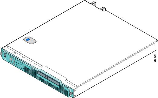
Each VQE Server runs on one Cisco Content Delivery Engine 110 (CDE110). If VQE Channel Provisioning Tool and VQE Client Channel Configuration Deliver Server are used, another Cisco CDE110 hosts these two facilities. The Cisco CDE110 (Figure 1-10) comes with the Red Hat Enterprise Linux 5.1 operating system and either the VQE-S or VCPT and VQE Client Channel Configuration Deliver Server software pre-installed.
Figure 1-10 Content Delivery Engine 110
The Cisco CDE110 appliance is a NEBS-3 and ETSI-compliant carrier-grade rack server. It is powered by two 64-bit Dual-Core Intel Xeon processor LV 5148 processors. For maximized bandwidth, it contains 4 GB of dual-channel Fully Buffered DIMM (FB-DIMM) memory at 667 MHz. For storage, the Cisco CDE110 has one 36-GB simple-swap, serial attached SCSI (SAS) hard disk drive. The optical drive is a CD/DVD RW combination drive.
The Cisco CDE110 has four integrated 10/100/1000 Mb Ethernet ports and a serial port for the system console. The Ethernet ports can be load-balanced for incoming multicast IPTV streams and for outgoing Unicast Retransmission and Rapid Channel Change streams to the VQE Clients.
The Cisco CDE110 has a 1-RU form factor and is available with redundant AC or DC hot-swappable power supplies. The Cisco CDE110's Telco Alarm Management features provide visual, audible (optional), and SNMP event indications of faults, consistent with the rigid requirements of the telecom central office environment.
For complete information on the Cisco CDE110, see the Cisco Content Delivery Engine 110 Hardware Installation Guide.