- What's in This Guide
- Configuring Cisco Unified Communications Manager for the Cisco TelePresence System
- Configuring Cisco TelePresence Features
- Loading Cisco Options Package (COP) Files on the Cisco TelePresence System
- Verifying and Troubleshooting the Cisco TelePresence System Configuration
- Configuring and Managing the Cisco Unified IP Phone
- Satellite Licenses for the Cisco TelePresence System
- Glossary
- Index
Cisco Unified Communications Manager Configuration Guide for the Cisco TelePresence System
Bias-Free Language
The documentation set for this product strives to use bias-free language. For the purposes of this documentation set, bias-free is defined as language that does not imply discrimination based on age, disability, gender, racial identity, ethnic identity, sexual orientation, socioeconomic status, and intersectionality. Exceptions may be present in the documentation due to language that is hardcoded in the user interfaces of the product software, language used based on RFP documentation, or language that is used by a referenced third-party product. Learn more about how Cisco is using Inclusive Language.
- Updated:
- April 15, 2014
Chapter: Configuring Cisco Unified Communications Manager for the Cisco TelePresence System
- Contents
- Adding a CiscoTelePresence Image to the Cisco Unified Communications Manager Server
- Configuring Phone Security Profile Information
- Using the Unified CM GUI to Add a CiscoTelePresence Device
- Device Information Area
- Protocol-Specific Information Area
- Certification Authority Proxy Function (CAPF) Information Area
- MLPP Information Area
- Product Specific Configuration Layout Area
- User Preferences Area
- Dial Plan Area
- Directory Number Area
- Global Location Area
- SSH Information Area
- External CTS Log Destination Area
- SNMP Configuration Parameters Area
- SNMP Trap Receiver Parameters Area
- Saving Your Settings
- Directory Number Information
- Directory Number Settings
- AAR Settings
- Call Forward and Call Pickup Settings
- MLPP Alternate Party Settings
- Line Settings for All Devices
- LineX on DeviceX
- Multiple Call/Call Waiting Settings on DeviceSEPXXXXXXXXXXXX
- Forwarded Call Information Display on DeviceSEPXXXXXXXXXXXX
Contents
This chapter explains how to download the Cisco TelePresence Administration Software from the cisco.com web site and configure a new device using the Cisco Unified Communications Manager web interface, and includes the following sections:
Adding a Cisco TelePresence Image to the Cisco Unified Communications Manager Server
This section describes the steps you take to add a new Cisco TelePresence Device to Cisco Unified Communications Manager (Unified CM) and includes the following topics:
- Downloading the Cisco TelePresence Software
- Installing the Cisco TelePresence COP File to the Unified CM Server
Downloading the Cisco TelePresence Software

Note Complete these steps prior to using your Cisco TelePresence Touch 12 device.
If you have not yet installed the Cisco TelePresence software onto the Unified CM server, complete the following steps to add it:
Note If you already downloaded the software and added it to the Unified CM server, skip this section and continue to the “Adding a Cisco TelePresence Device to the Unified CM Server” section to add a new device to Unified CM.
Step 1 Navigate to www.cisco.com .
Step 2 Click on the Log In button, then enter your username and password.
Step 4 Enter the following search term into the text box:
cisco telepresence administration software
Step 5 Click the Cisco TelePresence Administration Software hyperlink that displays.
Alternatively, you can click the Downloads tab and enter the name of your system into the text box.
Step 6 Click the Download Software hyperlink.
Step 7 Navigate to your product using the navigation tool that displays.
Step 8 Select the software that you require for your installation.
Systems that use a Cisco TelePresence Touch device for call control only require the Cisco TelePresence System and Cisco TelePresence Touch file. Systems that use a Cisco Unified IP phone for call control require the Cisco TelePresence System and the Cisco TelePresence Midlet Phone Application .jad and .jar files.
Step 9 Choose the latest release and click either Add to Cart or Download.
a. If you choose Add to Cart, click on Download Cart.
b. If you choose Download, click Accept License Agreement.
Step 10 Click Download and then Accept License Agreement, and follow the prompts to download the file.
Note For systems that use a Cisco TelePresence Touch device, the software to run the Touch device is included with the COP file. For systems that use a Cisco Unified IP phone for call control, the latest MIDlets software version is included with the Unified CM device pack. For more information about the files for systems that use a Cisco TelePresence Touch device, see the “Understanding COP Files” section.
Step 11 Copy these files to a Secure File Transfer Protocol (SFTP) server that is accessible by Unified CM.
Step 12 Load the system image onto the Unified CM server by completing the following steps:
a. Open a supported web browser.
Note The Cisco Unified CM Administration program requires Internet Explorer version 6, 7, 8 or 9 or Firefox version 3.6, 5 or 9.
b. In the address bar of the web browser, enter the following URL:
is the IP address or DNS name of the Cisco Unified Communications Manager server.
c. Upload the Cisco TelePresence system image to the Unified CM server by completing the steps in theInstalling the Cisco TelePresence COP File to the Unified CM Server section that follows.
Installing the Cisco TelePresence COP File to the Unified CM Server
To install the Cisco TelePresence system files to the Unified CM server, complete the following steps.
Step 13 Log in to the Unified CM administrative GUI.
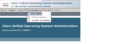
Step 14 From the Navigation drop-down list, on the top right of the GUI, select Cisco Unified OS Administration . Click Go to go to the Cisco Unified CM Administration home page.
The Cisco Unified Operation System Administration screen displays.
Note Log in with your username and password if prompted to do so.
Step 15 Navigate to Software Upgrades > Install/Upgrade .
Figure 1-1 Cisco Unified Operating System Administration Screen
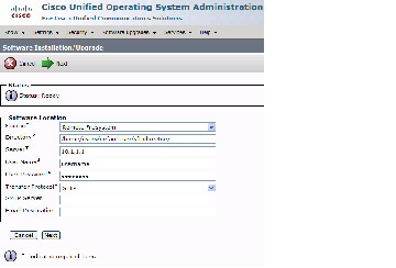
Step 16 In the Software Location area, specify the following information in the fields:
- In the Source drop-down list, select Remote Filesystem .
- In the Directory field, enter the location of the file on the SFTP server.
- In the Server field, enter the server name or IP address.
- In the User Name and User Password fields, enter the user name and password used to access the SFTP server.
- In the Transfer Protocol drop-down list, select SFTP .
Figure 1-2 Specifying SFTP Server and File Location
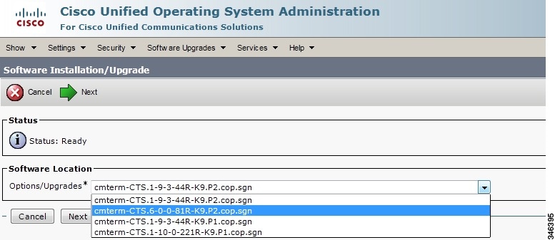
Unified CM accesses the SFTP server. The Software Location area lists the COP files that Unified CM finds in the directory that you specified.
Step 18 Choose the COP file that you want to install from the available file names in the Options/Upgrades drop-down list.
Figure 1-3 Specifying the COP File
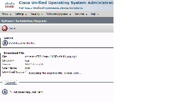
The Unified CM GUI shows the COP file being installed.
Figure 1-4 COP File Installation
Step 20 After installation completes, verify the file validity by completing the following steps:
a. Make a note of the information in the File Checksum Details area. This value is shown in Figure 1-5.
b. Log in to the SFTP server and enter the following command:
filename is the file name of the COP file on the SFTP server.
d. Make a note of the checksum value that displays as a result of the md5sum command.
e. Compare the MD5 Hash Value that displays in this area to the MD5 checksum value that you find in the COP file on the server and make sure that they match to ensure that the file is not corrupted.
f. If the values match, continue to the next step; if the values do not match, retry the file installation.
Figure 1-5 File Checksum Details Area
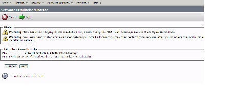
Step 21 Click Next to begin installation.
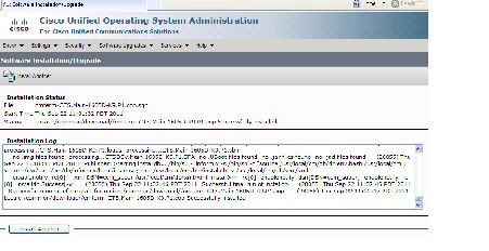
The installation log displays the installation progress.
After the .loads, codec and Touch 12 files are extracted, the interface displays a status of Complete in the Installation Status area.
Figure 1-6 Installation Status Area
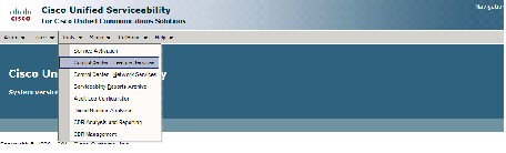
Step 22 From the Navigation drop-down list on the top right of the GUI, select Cisco Unified Serviceability and click Go .
The Cisco Unified Serviceability window displays.
Note Enter your user ID and password if prompted to do so.
Step 23 Restart the TFTP server by completing the following steps:
a. Navigate to Tools > Control Center - Feature Services .
Figure 1-7 Cisco Unified Serviceability Window
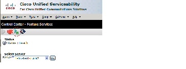
b. Choose the correct TFTP server from the drop-down list that displays and click Go .
c. In the CM Services area click the Cisco Tftp radio button.
d. Click the Restart button (either the Restart button on the bottom of the page or the button circled in red in Figure 1-8).
Figure 1-8 Restart Button in Features Services Page
Step 24 Add the Cisco TelePresence device to the Unified CM server by completing the steps in the “Adding a Cisco TelePresence Device to the Unified CM Server” section
Configuring Phone Security Profile Information
This section describes how to create and configure a phone security profile for a Cisco TelePresence device using Unified CM. This section contains the following tasks:
Adding a New Phone Security Profile for CTS
To add a new phone security profile for CTS:
Step 1 Log in to the Cisco Unified CM Administration interface.
Step 2 Choose System > Security Profile and click Phone Security Profile .
Step 3 Click the Add New button at the bottom of the window. The Phone Security Profile Configuration window appears.
Step 4 From the Phone Security Profile Type drop-down menu, choose the phone type .
Step 6 From the Select the phone security profile protocol drop-down menu, choose SIP .
Step 7 Click Next . The Phone Security Profile Configuration window appears containing your Product Type and Device Protocol selections.
Step 8 Proceed to Configuring the Phone Security Profile to complete the remaining tasks on the Phone Security Profile Configuration page.
Configuring the Phone Security Profile
In the Phone Security Profile Configuration window, verify your Product Type and Device Protocol settings:
SIP Phone Security Profile Information
If you chose SIP as the device protocol:
Step 1 From the Cisco Unified CM Administration interface, Choose System > Security Profile and click Phone Security Profile .
Step 2 Search for a Phone Security Profile using the search features or follow the steps in Adding a New Phone Security Profile for CTS.
Step 3 Enter configuration information on the Phone Security Profile Information page using the information in Table 1-1 as a guide.
Step 4 Click the Save button to save your settings.
Enter a name for the security profile. When you save the new profile, the name displays in the Device Security Profile drop-down list box in the Phone Configuration window for the phone type and protocol. |
||
Enter the number of minutes (in seconds) that the nonce value is valid. The default value equals 600 (10 minutes). When the time expires, Cisco Unified CM generates a new value. |
||
Choose Encrypted from the drop-down menu (recommended). Encrypted mode allows Cisco Unified CM to provide integrity, authentication, and encryption for the phone. A TLS connection that uses AES128/SHA opens for signaling, and SRTP carries the media for all phone calls on all SRTP-capable SIP hops. Note The Media is Encrypted icon (closed lock) is displayed on the screen only when the Device Security mode is set to encrypted and cluster security mode is set to 1 (mixed mode). To configure and verify cluster security mode, see the Verifying the Cisco Unified Communications Manager Security Mode section of the Cisco TelePresence Security Solutions Guide . |
||
When Device Security Mode is Non Secure, choose one of the following options from the drop-down list box (not all options may display):
When Device Security Mode is Authenticated or Encrypted, TLS specifies the Transport Type. TLS provides signaling integrity, device authentication, and signaling encryption (encrypted mode only) for SIP phones. Note If Device Security Mode cannot be configured in the profile, the transport type specifies UDP. |
||
When this box is checked, Cisco Unified CM encrypts phone downloads from the TFTP server. This option exists for Cisco phones only. |
||
When this box is checked, Cisco Unified CM omits digest credentials in phone downloads from the TFTP server. This option exists for Cisco Unified IP SIP Phone models 7905, 7912, 7940, and 7960 only. |
Phone Security Profile CAPF Information
To configure the Phone Security Profile CAPF Information fields:
Step 1 Enter Phone Security Profile CAPF Information using the information in Table 1-2 as a guide.
Step 2 Click the Save button to save your settings.
Parameters Used in Phone Field
To configure the Parameters Used in Phone Field:
Step 1 Enter the SIP Phone Port information using the information in Table 1-3 as a guide.
Step 2 Click the Save button to save your settings.
Adding a Cisco TelePresence Device to the Unified CM Server
Note Before you begin this procedure, note the MAC address of the Cisco TelePresence device. See the “Before You Begin” section for information about determining the MAC address.
This section includes the steps you take to add a new Cisco TelePresence device to the Unified CM server and includes the following steps:
- Using the Unified CM GUI to Add a Cisco TelePresence Device
- Device Information Area
- Protocol-Specific Information Area
- Certification Authority Proxy Function (CAPF) Information Area
- MLPP Information Area
- Product Specific Configuration Layout Area
- User Preferences Area
- Dial Plan Area
- Global Location Area
- SSH Information Area
- External CTS Log Destination Area
- SNMP Configuration Parameters Area
- SNMP Trap Receiver Parameters Area
- Saving Your Settings
Using the Unified CM GUI to Add a Cisco TelePresence Device
To add a new Cisco TelePresence device to the Unified CM server, complete the following steps.
Step 1 Log in to the Cisco Unified CM Administration interface.
Step 2 If required, choose the Cisco Unified CM Administration drop-down choice and click Go .
Step 3 From the Device drop-down menu, choose Phone. The Find and List Phones Page appears.
Step 4 Click the Add New button at the bottom of the window. The Add a New Phone window appears.
Step 5 In the Add a New Phone window, click the Phone Type drop-down list and choose Cisco TelePresence system that corresponds with your device.
You added this phone type when you downloaded and applied the Cisco TelePresence file in the “Installing the Cisco TelePresence COP File to the Unified CM Server” section,
Step 6 Click Next to display the Phone Configuration window.
Step 7 Fill out the fields in the Phone Configuration window. Refer to Table 1-4 through Table 1-14 for a description of these fields.
Step 8 When you have finished making your changes, click Save to save your settings.
Device Information Area
Table 1-4 provides you with a description of the fields in the Device Information Area.
Note Fields marked with an asterisk ( * ) in the administration interface are required entries.
Read-only. Indicates whether the system is Registered with Cisco Unified Communications Manager and lists the registered Unified CM address. |
|
IP address for the Cisco TelePresence System. After you add the device, you can click on the address to see information for that phone in a new window. |
|
MAC address for the Cisco TelePresence primary codec. For example, 000DD12345A1. |
|
Your device pools. Choose a device pool from the drop-down menu. Click View Details to open the Device Details window, which includes the following system setting information: |
|
Your configured devices. Leave field as < None> . Click View Details to open t he Common Device Configuration Detail wi ndow, which includes the following system setting information: |
|
|
Note Unless you have created extra button templates, you will see the default button template for your device. |
|
Softkey Template (systems that use a Cisco Unified IP Phone for call control only) |
Note This field is only for systems that use a Cisco Unified IP Phone for call control. |
|
Note Information in this field reflects Calling Search Spaces that have been created on this Unified CM. |
|
|
Note This field supports user locales listed in Table 2-4. |
|
|
Note This field supports network locales listed in Table 2-4. |
|
|
Click View Current Device Mobility Settings to open the Device Mobility Details window, which shows the current device mobility settings. |
|
Specify required version of Cisco TelePresence System if no device default is set. |
|
|
Note When you are finished making changes, click Save to save your settings. |
|
Protocol-Specific Information Area
Table 1-5 provides you with a description of the fields in the Protocol-Specific Information area.
Note Fields marked with an asterisk ( * ) in the administration interface are required entries for basic configuration.
Cisco TelePresence name of system - Standard SIP Non-Secure Profile (default) Note For more information about configuring Cisco Unified CM security features, refer to the Cisco Unified Communications Manager Security Guide, Release 7.1(2). |
|
|
Note Information in this field reflects Calling Search Spaces that have been created on this Unified CM. |
|
|
Note Information in this field reflects Calling Search Spaces that have been created on this Unified CM. |
|
|
Information in this field reflects SIP profiles that have been created on this Unified CM. |
|
|
Note When you are finished making changes, click Save to save your settings. |
|
Certification Authority Proxy Function (CAPF) Information Area
Table 1-6 describes the fields in the Certification Authority Proxy Function (CAPF) Information area.
Note This option will not be visible unless you have enabled CAPF on the Cisco Unified Communications Manager service parameter.
The Security Profile contains additional CAPF settings.
For more information about CAPF, refer to the Securing Cisco TelePresence Products document for your software release, available at the following URL:
http://www.cisco.com/en/US/partner/products/ps8332/
products_installation_and_configuration_guides_list.html
Note Fields marked with an asterisk ( * ) in the administration interface are required entries for basic configuration.
MLPP Information Area
In the MLPP Information area, leave the MLPP Domain field at the default of <None>.
Product Specific Configuration Layout Area
Table 1-7 contains descriptions of the Product Specific Configuration Layout information fields.
Note Fields marked with an asterisk ( * ) in the administration interface are required entries for basic configuration.
Note Not all choices are available for all devices; some choices are product-specific.
For more information about these fields, see the “Product Specific Configuration Layout” section.
Indicates the type of Cisco TelePresence system you have installed. |
|
When enabled, allows access to the Cisco TelePresence Web Administration interface. |
|
Conference room name as described in Microsoft Exchange or Domino. Used to schedule conference calls. This field accepts a text string with a maximum of 64 characters. Note If you have the Cisco TelePresence Manager application, the name of the conference room is required. The name must exactly match the resource mailbox (including domain name) as it is entered in the Microsoft Exchange or Domino database. It will be used to schedule conference calls. |
|
Maximum duration (in minutes) allowed for a Cisco TelePresence conference call.
Note This feature is coordinated with the Maximum Call Duration Timer in the Cisco Unified Communications Manager service parameters. If values other than 0 are entered for either of these fields, the smaller value takes precedence. |
|
Bandwidth used by the system. Higher bandwidth increases video quality, but may also cause packets to be dropped and video to be interrupted.
If your system uses a Cisco Unified IP Phone for call control, note the following caveats for the 720p (Lite) choice: – The audio addin conf softkey is not available. – You must have MIDlets installed on the Unified CM. For more information about 720p (Lite), see Quality Per Display - 720p (Lite). Note Limited bandwidth mode: 360p may be listed as an option in this field but is not yet available; it is supported in a future release. |
|
Sets the bandwidth allocation ratio between conference video and presentation video. Default value of this parameter is a weight of 8 for main video and a weight of 2 for presentation video for a total weight of 10.
See also the TX Software Features chapter of the Administration Guide for Cisco TelePresence TX Software Release 6.0 . |
|
Main Display Frames Per Second* (TX13x0 and TX9x00 systems only)* |
Selects the frame rate, or frames per second (fps), on the main display screen. Choice are: |
Indicates whether you have a presentation input device. Choices are: Note This parameter must correctly reflect how your system is configured. Any discrepancy will cause CTS to function improperly. |
|
Indicates if you have a presentation output device. Choices are: Note This parameter must correctly reflect how your system is configured. Any discrepancy will cause CTS to function improperly. |
|
Defines how the lights operate in a CTS conference room. Choices are: Note On the CTS 500, the lights are powered by the display. When the display turns off according to the display settings in Unified CM, the lights also turn off. However, if you have chosen the “On all the time” setting for the lights, the setting is not honored during power saving/non-business hours (when display settings are not active). To bypass power saving/non-business hours defaults, extend the business hours to all the time in the Display On Duration field. See also Notes About Auxiliary Control. |
|
Wideband Codec. Indicates whether Cisco Telepresence endpoints will advertise the G.722 audio codec to Unified CM. When enabled, preference is given to this audio codec.
See the Configuring Wideband Codec section of the Cisco Unified IP Phone 7931G Administration Guide for Cisco Unified Communications Manager 6.1(3) (SCCP) for more information about the G.722 codec. |
|
Configures the external syslog address. Allowed values: Syslog address format can be either: Host is either a hostname or IP address (up to 60 characters long). Port is a number between 0 and 65535. Default is 514. |
|
Configures the alternate Cisco Unified CM IP address that the CTS should query in the directory. This field can be either an IP address, domain name, or URL. Maximum length: 64. |
|
Configures the address (IP address or DNS name) of the Cisco TelePresence Recording Server (CTRS). Maximum length: 64. |
|
Selects the frames per second (fps) for the external presentation. |
|
Specifies the number that the system dials when the user presses the Live Desk button or softkey. For more information, refer to the Live Desk in Cisco Unified CM section of the Release Notes for Cisco TelePresence System Software Release 1.9 . |
User Preferences Area
Table 1-8 shows the fields in the User Preferences area.
Note Fields marked with an asterisk ( * ) in the administration interface are required entries for basic configuration.
Specifies the days of the week that the Cisco TelePresence system display remains off by default. Choices are Monday through Sunday. Default is Saturday |
|
Specifies the time of day that the Cisco TelePresence system display(s) will remain on after being turned on. Enter a value using a 24-hour format where 00:00 indicates 12:00 midnight and 23:59 indicates 11:59 pm. Note If you clear the default value so that the field is blank, the display(s) turn off after the completion of each call. |
|
Specifies the length of time the Cisco TelePresence system display(s) will remain on if a “Display On Time” value is defined. Enter a value using a 24-hour format, where 1:30 indicates one hour and thirty minutes. The maximum value is 24:00 (24 hours). Note If you clear the default value so that the field is blank, then the display turns off at 11:59 pm. |
|
Selects the idle screen (“home screen”) on the phone interface when CTS is idle. Choices are: |
|
Allows the CTS endpoint to override the Unified CM DN settings on a shared line.
– Internal calls are set to Auto Answer or No Auto Answer – External calls are set to No Auto Answer Note If your system uses a Cisco Unified IP phone for call control, you must configure the phone in Unified CM so that CTS Auto Answer is turned off. Otherwise, the phone might answer the call instead of the CTS system.
Note Auto Answer is set to No by default on the CTS 500 32.” |
|
Number of second-row conference room seats supported in a CTS 3210 or TX9200 meeting room. Default is 12 seats. |
|
Table Microphone Count (CTS 1100, CTS 1300 and TX1310 systems only)* |
Number of microphones that are available. Choose a number from the drop-down menu. Note See the “Setting Up the Microphones” section of the Cisco TelePresence System 1300 Assembly, First-Time Setup, and Field-Replaceable Unit Guide for more information. |
|
Note Camera loopback is always in self view or flipped mode. See the “Self View Control” section for information about using the Self View feature. |
|
Check this box to enable audio echo cancellation in the CTS. Default is True. Note This box is not available for CTS 500-32 and CTS 500-37 systems running Unified CM version 8.5 and higher (but is still available on all other CTS devices). To enable or disable AEC on the CTS 500-32 and CTS 500-37, use the set audio aec disable and set audio aec enable command-line interface (CLI) commands. |
|
Check this box to enable the a ring tone at the termination of a call. Default is True. |
|
Check this box to enable the single microphone mute feature. Default is disabled. |
|
Optional Hardware
Click the appropriate check boxes in the Optional Hardware area if the following optional hardware devices are installed:
- presentation codec: a CTS 500-37, CTS 1100 Series, CTS 1300-65, or CTS 3000 Series endpoint.
- A/V Expansion Box (audio/video extension unit)
- Auxiliary Control Unit
Note This parameter must correctly reflect how your system is configured. Any discrepancy will cause the CTS to function improperly. See the “Product Specific Configuration Layout Area” section to find the default values for your system.
Some check boxes will not appear for some device types. The CTS 1100 and the CTS 1300 use the Auxiliary Control Unit by default, for example, so these boxes are automatically checked.
See the Cisco TelePresence Hardware Options and Upgrade Guide for more information about installing and maintaining optional hardware.
Figure 1-9 and show additional features that you can manage from the Product Specific Configuration Layout window:
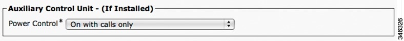
Auxiliary Control Unit
Required if installed. Only the following systems use the Auxiliary Control Unit: Cisco TelePresence Systems 1000, 1100, 1300-65, 3000, 3010, 3200
Choose the appropriate option from the drop-down list for Auxiliary Control Unit Power Control:
- On with calls only, as shown in Figure 1-9. See Notes About Auxiliary Control.
- On with display settings
- On all the time
Figure 1-9 Auxiliary Control Unit Settings
See the “Product Specific Configuration Layout Area” section to find the default values for your system. See also the Cisco TelePresence Hardware Options and Upgrade Guide for more information about hardware options.
Note The CTS 1100 and the CTS 1300-65 use the Auxiliary Control Unit by default.
Notes About Auxiliary Control
- Auxiliary Video Input—On some systems, auxiliary video input may be displayed on the primary 65-inch main screen even when the auxiliary presentation display is powered off or is disconnected from the presentation codec.
Ensure that the Auxiliary presentation display is powered on and connected at all times. Consult the manual for your display to make any configuration changes.
- Auxiliary Power Control: On With Calls Only—On some systems when Power Control is configured for “On with calls only” and there is an Auxiliary HDMI port connected (Active Display or Projector), the lights will remain on for 5 minutes after the call has been terminated. If no Auxiliary HDMI port is in use, the lights will go off immediately.
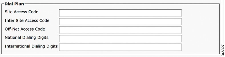
Dial Plan Area
Provide dial plan information for the Cisco TelePresence device using the descriptions in Table 1-9 . Click Save to save your settings.

Tip Only numeric values are allowed.
Figure 1-10 Dial Plan Settings
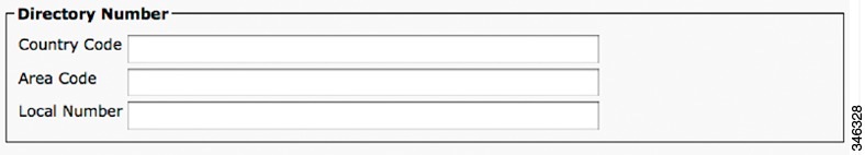
Directory Number Area
Provide directory number information for the Cisco TelePresence device using the descriptions in Table 1-10 . Click Save to save your settings.
Tip Only numeric values are accepted.
Figure 1-11 Directory Number Settings
Global Location Area
Provide global location information for the Cisco TelePresence device using the descriptions in Table 1-11 as a guide. Click Save to save your settings.
Figure 1-12 Global Location Settings
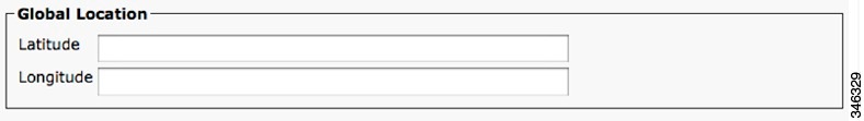
Indicates the site’s latitude. The format for this field is as follows: dd mm ss P |
||
Indicates the site’s longitude. The format for this field is as follows: ddd mm ss P |
SSH Information Area
Figure 1-13 shows the Secure Shell (SSH) Information window.
Figure 1-13 SSH Information Window
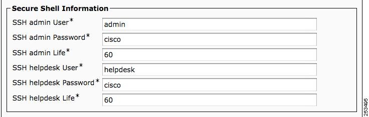
Using the information in Table 1-12 as a guide, provide a username and password for the SSH account that will be used to access the command line interface (CLI) and the Cisco TelePresence Web Administration interface.
Changing the SSH username and password also changes the username and password for the Cisco TelePresence administration interface.
Click Save to save your settings.
Username for the Secure Shell account. Used for SSH access and to access the Cisco TelePresence administration interface. Cisco Technical Assistance Center (TAC) uses secure shell for troubleshooting and debugging. Contact TAC for further assistance. Default user name is admin. The length of this username can be between 6 and 64 characters. This username supports CLI multi-level access (MLA). Do not use any of the following user names: apache , daemon , help , helpdesk , nobody , operator , or shutdown . Usernames and passwords can contain upper and lower case alphanumeric characters and the underscore and dash characters. User names cannot start with a - (dash) or _ (underscore). Note for SSH admin and SSH helpdesk user names: You cannot swap the SSH admin user name and the SSH Helpdesk user name without performing an interim user name change. For example, given an admin user name of minad and a helpdesk name of deskhelp , perform the following steps to change the admin name to deskhelp and the helpdesk name to minad : 1. Change the admin user name to a temporary password (for example, admintemp ) and change the helpdesk name to minad . 2. Click Save , then click Apply Config . 3. Wait until the “Calls Not Possible” pop-up screen disappears from the Touch Device. |
||
Password for the SSH account to be used for SSH access and to access the Cisco TelePresence Web Administration interface. Default password is cisco. |
||
Sets the password expiration duration to ensure that the system is protected when using Cisco TelePresence Command Line Interface (CLI). You must periodically update this password. See Figure 1-13 to see updated SSH fields that are used to update your password. Password expiration can be set to have a value between 0 and 365. A setting of 0 disables password aging. Default is 60 days. Unless the configured life has been disabled (by being set to 0), password age is set to have 2 days remaining in the following situations:
An on-screen warning message is sent to the CLI user when 14 days remain on the current password, and so on until the password expires. If the password is allowed to expire, the system ignores the CLI login attempt and the user cannot access the system unless a new password is created by entering information in the SSH Information Area window. Save your changes by clicking Restart. This enables the updated configuration to be read, applied to the CTS, and then Calling Service is restarted. Alternately you can click Reset, which causes the CTS to reboot. On startup, the CTS reads the Unified CM configuration and applies any changes. See the Cisco TelePresence System Command-Line Interface Reference Guide for more information. |
||
Username for the Helpdesk user secure shell account. Used for SSH access and to access the Cisco TelePresence administration interface. Cisco Technical Assistance Center (TAC) uses secure shell for troubleshooting and debugging. Contact TAC for further assistance. Default user name is helpdesk. The length of this username can be between 6 and 64 characters. The helpdesk user has limited access to the CLI and no set commands are allowed. Do not use any of the following user names: admin , apache , daemon , nobody , operator , or shutdown . User names and passwords can contain upper and lower case alphanumeric characters and the underscore and dash characters. User names cannot start with a - (dash) or _ (underscore). Note for SSH admin and SSH helpdesk user names: You cannot swap the SSH admin user name and the SSH Helpdesk user name without performing an interim user name change. For example, given an admin user name of minad and a helpdesk name of deskhelp , perform the following steps to change the admin name to deskhelp and the helpdesk name to minad : 1. Change the admin user name to a temporary password (for example, admintemp ) and change the helpdesk name to minad . 2. Click Save , then click Apply Config . 3. Wait until the “Calls Not Possible” pop-up screen disappears from the Touch Device. |
||
Password for the SSH account to be used for SSH access and to access the Cisco TelePresence Web Administration interface. Default password is cisco. |
||
External CTS Log Destination Area
This subsection comprises six fields. The first four configure the CTS to “push” the captured log file to a remote server:
The second two fields configure the CTS to automatically capture logs on a periodic basis:
Note These two sets of fields can be configured independently of each other.
Enter external CTS log address information into the fields using the information in Table 1-12 as a guide. Click Save to save your settings.
SNMP Configuration Parameters Area
Using the information in Table 1-14 as a guide, provide the required Simple Network Management Protocol (SNMP) configuration parameters for accessing the SNMP server that is associated with the Cisco TelePresence device. Figure 1-14 shows the SNMP Configuration Parameters screen.
Note Passwords in SNMP parameter fields can only be 32 characters in length.
Figure 1-14 SNMP Configuration Parameters
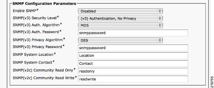
Note All SNMP fields are marked to reflect the applicable SNMP version.
SNMP Trap Receiver Parameters Area
Table 1-15 lists the preset SNMP trap receiver parameters that are associated with the Cisco TelePresence device.
Note Using the information in Table 1-15 as a guide, you can set up to five trap destinations.
Managing SNMP MIBs and SNMP Traps
See the Cisco TelePresence System Message Guide for information about managing SNMP MIBs and Traps.
Saving Your Settings
When you have finished making changes to the parameters in the Phone Configuration window, click Save then Apply Config. The Apply Configuration Information window appears showing the chosen device name.
Note You must save the configuration before continuing. When you click Apply Config, the device might go through a restart. When restart is initiated, connected calls will be preserved but calls in progress may be dropped.
Configuring the Directory Number for the Cisco TelePresence Device
Note You must restart your system after you have completed the configuration tasks in this section.
Use the information in the following sections to configure the directory number in the Directory Number Configuration window. When you have finished entering configuration information, click Save and follow the prompts to restart the system.
- Directory Number Information
- Directory Number Settings
- AAR Settings
- Call Forward and Call Pickup Settings
- MLPP Alternate Party Settings
- Line Settings for All Devices
- Line X on Device X
- Multiple Call/Call Waiting Settings on Device SEPXXXXXXXXXXXX
- Forwarded Call Information Display on Device SEPXXXXXXXXXXXX
Directory Number Information
To configure settings in the Directory Number Information box, complete the following steps:
Step 1 If you have not already done so, click Add a new DN in the Association Information box to open the Directory Number Configuration window.
Step 2 Enter the directory information using the information in Table 1-16 as a guide.
Step 3 Make sure that the check box at the bottom of the Directory Number Information section is marked as indicated:
Active: Checked
Step 4 Click Save to save your settings.
Directory Number Settings
The fields described in Table 1-17 are left unchanged in the Directory Number Settings box:
Set to “NoVoiceMail” if you do not have voicemail capability. |
||
|
Additional drop-down menu choices: Note Optionally, you can set Auto Answer Off and instead configure the Product Specific Configuration Layout Area “CTS Auto Answer” setting to have the CTS pick up the call. Note To assign a directory number for the shared-line Cisco Unified IP Phone, choose Auto Answer with Speakerphone. See the “Assigning a Directory Number for the Shared-Line Cisco Unified IP Phone” section. Note If you are using the IP Phone and the call is connected as audio only, verify that the following check-boxes are checked: |
AAR Settings
The fields described in Table 1-18 are left unchanged in the AAR Settings box:
Call Forward and Call Pickup Settings
The fields described in Table 1-19 are left unchanged in the Call Forward and Call Pickup Settings box:
MLPP Alternate Party Settings
The fields described in Table 1-20 are left unchanged in the multilevel precedence and preemption (MLPP) Alternate Party Settings box:
Line Settings for All Devices
The fields described in Table 1-21 are left unchanged in the Line Settings for All Devices Settings box:
Line X on Device X
Manage the TFTP profile for the Cisco TelePresence endpoint by configuring the meeting room name so that the room name appears on the Cisco WebEx Participant List, as shown in Figure 1-15.
Figure 1-15 Display (Internal Caller ID) Fields
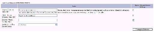
Line X on Device X Fields are described in Table 1-22 .
Leave the default setting. For Cisco WebEx, enter your room name so that the room name appears on the Cisco WebEx Participant List. Note Display text for a line appearance is intended for displaying text such as a name instead of a directory number for internal calls. If you specify a number, the person receiving a call may not see the proper identity of the caller. |
||
Leave the default setting. For Cisco WebEx, enter your room name so that the room name appears on the Cisco WebEx Participant List. |
||
Leave the default setting. Applies to this line when any line on the phone has a call in progress. |
||
Multiple Call/Call Waiting Settings on Device SEPXXXXXXXXXXXX
The Multiple Call/Call Waiting settings make it possible to place a meeting on hold, dial a phone number, and have up to four active calls on one device. This feature is useful for adding phone calls to a Cisco TelePresence meeting.
The default setting for the maximum number of additional phone calls allowed on the CTS Cisco Unified IP phone is 4.
Note Valid range for Maximum Number of calls is 1-46.
To configure multiple call waiting settings on a specific device:
Step 1 Enter configuration settings in the fields provided using the information in Table 1-23 as a guide.
Step 2 Click Save to save your settings.
Where to Go Next
If you have an IP Phone, proceed to Chapter5, “Configuring and Managing the Cisco Unified IP Phone”
 Feedback