Catalyst 6500 Series Switch Chassis Overview
This chapter describes the Catalyst 6500 series switches and contains these sections:
• Catalyst 6503 Switch
•Catalyst 6503-E Switch
•Catalyst 6504-E Switch
•Catalyst 6506 Switch
•Catalyst 6506-E Switch
•Catalyst 6509 Switch
•Catalyst 6509-E Switch
•Catalyst 6509-NEB Switch
•Catalyst 6509-NEB-A Switch
•Catalyst 6509-V-E Switch
•Catalyst 6513 Switch
•Catalyst 6513-E Switch
Note Throughout this publication, except where noted, the term supervisor engine is used to refer to Supervisor Engine 2, Supervisor Engine 32, and Supervisor Engine 720.
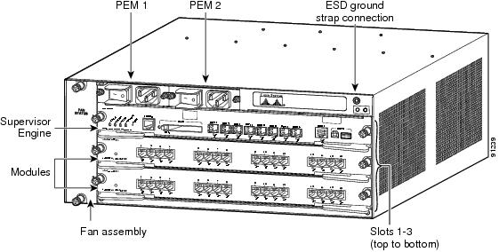
Catalyst 6503 Switch
The Catalyst 6503 switch is a 3-slot horizontal chassis. Figure 1-1 shows the front view of the chassis and Figure 1-2 shows the rear view of the chassis. Table 1-1 provides a description of the major switch features. Table 1-2 lists specifications of the Catalyst 6503 switch chassis.
Figure 1-1 Catalyst 6503 Switch Chassis—Front View
Figure 1-2 Catalyst 6503 Switch—Rear View
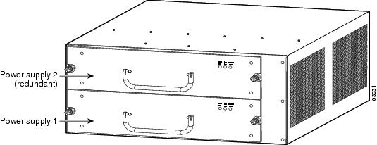
Table 1-1 Catalyst 6503 Switch Features
|
|
|
Chassis |
Three horizontal slots. Slots are numbered from 1 (top) to 3 (bottom). |
Power supplies |
•Supports one or two power supplies. The following power supplies are supported: –950 W AC-input power supply (PWR-950-AC) –950 W DC-input power supply (PWR-950-DC) –1400 W AC-input power supply (PWR-1400-AC) Note For information and specifications for each of the supported power supplies, refer to Appendix A, "Power Supply Specifications," in the Catalyst 6500 Series Switches Installation Guide. •Installed power supplies can be of different wattage ratings. Installed power supplies can be both AC-input, both DC-input, or one AC-input and one DC-input. Power supplies can be configured in either redundant or nonredundant mode. Note For Catalyst 6503 and Catalyst 6503-E chassis that are equipped with DC-input power supplies, the system (NEBS) ground serves as the primary safety ground and must be installed. The DC-input power supplies for these chassis do not have a separate ground. •All Catalyst 6500 series AC-input power supplies require single-phase source AC. Source AC can be out of phase between multiple power supplies or multiple AC-power plugs on the same power supply because all AC power supply inputs are isolated. •Single power supplies are installed in the lower power supply bay. The second power supply is installed in the upper power supply bay. |
Supervisor engines |
•Supports Supervisor Engine 2, Supervisor Engine 32, Supervisor Engine 32 PISA, and Supervisor Engine 720. –Supervisor engines are installed in slot 1 and slot 2. –Supervisor Engine 720 with 10-GB uplink ports (VS-S720-10G-3C and VS-S720-10G-3CXL) is not supported on the Catalyst 6503 chassis. –Supervisor Engine 32, Supervisor Engine 32 PISA, or Supervisor Engine 720 requires that the optional high-speed fan tray (FAN-MOD-3HS) be installed in the chassis. –Supervisor Engine 720 has built-in switching fabric. Switch Fabric Modules (WS-C6500-SFM and WS-X6500-SFM2) are not supported by Supervisor Engine 720 and cannot be installed in the same chassis. –Supervisor Engine 32 and Supervisor Engine 32 PISA do not support the Switch Fabric Modules ((WS-C6500-SFM and WS-X6500-SFM2). •The uplink ports are fully functional on the redundant supervisor engine while it is in standby mode. Note In systems with redundant supervisor engines, both supervisor engines must be the same model and have the same daughter card configurations. Each supervisor engine must have the resources to run the switch on its own, which means all supervisor engine resources are duplicated. Identical supervisor engine memory configurations are recommended, but are not required as long as the supervisor engine with the smaller memory configuration is sufficient to run the configured features of the switch. Additionally, each supervisor engine must have its own flash device and console port connections. |
Modules |
•Supports up to two Catalyst 6500 series modules. •Does not support the WS-C6500-SFM and WS-X6500-SFM2 Switch Fabric Modules. •Does not support the WS-X67xx modules. •Some Catalyst 6500 series modules: –Are not supported –Require that you install a Supervisor Engine 720 –Have chassis slot restrictions –Require a specific software release level Check your software release notes for specific information on module support. |
Table 1-2 Catalyst 6503 Switch Specifications
|
|
|
|
|
|
Temperature, operating |
Certified for operation: 32° to 104°F (0° to 40°C) Designed and tested for operation: 32° to 130°F (0° to 55°C) Note The Catalyst 6500 series switches are equipped with internal air temperature sensors that are triggered at 104°F (40°C) generating a minor alarm and at 131°F (55°C) generating a major alarm. |
Temperature, nonoperating and storage |
-4° to 149°F (-20° to 65°C) |
Thermal transition |
0.5°C per minute (hot to cold) 0.33°C per minute (cold to hot) |
Humidity (RH), ambient (noncondensing) operating |
10% to 85% |
Humidity (RH), ambient (noncondensing) nonoperating and storage |
5% to 95% |
Altitude, operating |
Certified for operation: 0 to 6500 feet (0 to 2000 m) Designed and tested for operation: -200 to 10,000 feet (-60 to 3000 m) |
|
|
|
Dimensions (H x W x D) |
•7 x 17.37 x 21.75 in. (17.78 x 44.12 x 55.25 cm). •Chassis requires 4 RU. •Chassis can be mounted in equipment racks that meet ANSI/EIA 310-D and ETS 300-119 standards. |
Weight |
•Chassis only: 27 lb (12.25 kg). •Chassis fully configured with 1 supervisor engine, 2 modules,
2 AC-input PEMs, and 2 AC-input power supplies: 85.4 lb (38.7 kg). |
|
|
•FAN-MOD-3 (standard fan tray)—170 CFM •FAN-MOD-3HS (optional high-speed fan tray)—270 CFM Note To maintain proper air circulation through the Catalyst switch chassis, we recommend that you maintain a minimum 6-inch (15 cm) separation between a wall and the chassis air intake or a wall and the chassis air exhaust. You should also allow a minimum separation of 12 inches (30.5 cm) between the hot air exhaust on one chassis and the air intake on another chassis. Failure to maintain adequate air space can cause the chassis to overheat and the system to fail. On Catalyst chassis in which the airflow is from front to back, the chassis may be placed side-by-side. |
Catalyst 6503-E Switch
The Catalyst 6503-E switch is an enhanced version of the Catalyst 6503. Figure 1-3 shows the front view of the chassis and Figure 1-4 shows the rear view of the chassis. Table 1-3 provides a description of the major switch features. Table 1-4 lists the specifications of the Catalyst 6503-E switch chassis.
Figure 1-3 Catalyst 6503-E Switch—Front View
Figure 1-4 Catalyst 6503-E Switch—Rear View
Table 1-3 Catalyst 6503-E Switch Features
|
|
|
Chassis |
Three horizontal slots. Slots are numbered from 1 (top) to 3 (bottom). |
Power supplies |
•Supports one or two power supplies. The following power supplies are supported: –PWR-950-AC (950 W AC-input power supply) –PWR-950-DC (950 W DC-input power supply) –PWR-1400-AC (1400 W AC-input power supply) Note For information and specifications for each of the supported power supplies, refer to Appendix A, "Power Supply Specifications," in the Catalyst 6500 Series Switches Installation Guide. •Installed power supplies can be of different wattage ratings. Installed power supplies can be both AC-input, both DC-input, or one AC-input and one DC-input. Power supplies can be configured in either redundant or nonredundant mode. •All Catalyst 6500 series AC-input power supplies require single-phase source AC. Source AC can be out of phase between multiple power supplies or multiple AC-power plugs on the same power supply because all AC power supply inputs are isolated. •Supervisor Engine 2T requires a 1400 W power supply to operate. •Single power supplies are installed in the lower power supply bay. The second power supply is installed in the upper power supply bay. |
Supervisor engines |
•Supports Supervisor Engine 2, Supervisor Engine 32, Supervisor Engine 32 PISA, Supervisor Engine 720, Supervisor Engine 720-10GE, and Supervisor Engine 2T. –Supervisor engines are installed in slot 1 and slot 2. –Supervisor Engine 720, Supervisor Engine 720-10GE, and Supervisor Engine 2T have built-in switching fabric and do not support Switch Fabric Modules (WS-C6500-SFM and WS-X6500-SFM2). –Supervisor Engine 32 and Supervisor Engine 32 PISA do not support the Switch Fabric Modules ((WS-C6500-SFM and WS-X6500-SFM2). •The uplink ports are fully functional on the redundant supervisor engine when it is in standby mode. Note In systems with redundant supervisor engines, both supervisor engines must be the same model and have the same daughter card configurations. Each supervisor engine must have the resources to run the switch on its own, which means all supervisor engine resources are duplicated. Identical supervisor engine memory configurations are recommended, but are not required as long as the supervisor engine with the smaller memory configuration is sufficient to run the configured features of the switch. Additionally, each supervisor engine must have its own flash device and console port connections. |
Modules |
•Chassis supports up to two Catalyst 6500 series modules. •Chassis does not support the WS-C6500-SFM and WS-X6500-SFM2 Switch Fabric Modules. •Some Catalyst 6500 series modules: –Are not supported –Require that you install a Supervisor Engine 720 or Supervisor Engine 2T –Have chassis slot restrictions –Require a specific software release level Check your software release notes for specific information on module support and restrictions. |
Table 1-4 Catalyst 6503-E Switch Specifications
|
|
|
|
|
|
Temperature, operating |
Certified for operation: 32° to 104°F (0° to 40°C) Designed and tested for operation: 32° to 130°F (0° to 55°C) Note The Catalyst 6500 series switches are equipped with internal air temperature sensors that are triggered at 104°F (40°C) generating a minor alarm and at 131°F (55°C) generating a major alarm. |
Temperature, nonoperating and storage |
-4° to 149°F (-20° to 65°C) |
Thermal transition |
0.5°C per minute (hot to cold) 0.33°C per minute (cold to hot) |
Humidity (RH), ambient (noncondensing) operating |
10% to 85% |
Humidity (RH), ambient (noncondensing) nonoperating and storage |
5% to 95% |
Altitude, operating |
Certified for operation: 0 to 6500 feet (0 to 2000 m) Designed and tested for operation: -200 to 10,000 feet (-60 to 3000 m) |
|
|
|
Dimensions (H x W x D) |
•7 x 17.37 x 21.75 in. (17.78 x 44.12 x 55.25 cm). •Chassis requires 4 RU. •Chassis can be mounted in equipment racks that meet ANSI/EIA 310-D and ETS 300-119 standards. |
Weight |
•Chassis only: 33 lb (15 kg). •Chassis fully configured with 1 supervisor engine, 2 modules,
2 AC-input PEMs, and 2 AC-input power supplies: 85.4 lb (38.7 kg). |
|
|
WS-C6503-E-FAN—282 CFM Note To maintain proper air circulation through the Catalyst switch chassis, we recommend that you maintain a minimum 15 cm (6-inch) separation between a wall and the chassis air intake or a wall and the chassis air exhaust. You should also allow a minimum separation of 12 inches (30.5 cm) between the hot air exhaust on one chassis and the air intake on another chassis. Failure to maintain adequate air space can cause the chassis to overheat and the system to fail. On Catalyst chassis in which the airflow is from front to back, the chassis may be placed side-by-side. |
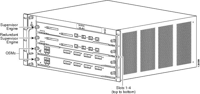
Catalyst 6504-E Switch
The Catalyst 6504-E switch is a 4-slot horizontal enhanced chassis. Figure 1-5 shows the front view of the chassis and Figure 1-6 shows the rear view of the chassis. Table 1-5 provides a description of major switch features. Table 1-6 lists the specifications of the Catalyst 6504-E switch chassis.
Figure 1-5 Catalyst 6504-E Switch—Front View
Figure 1-6 Catalyst 6504-E Switch—Rear View
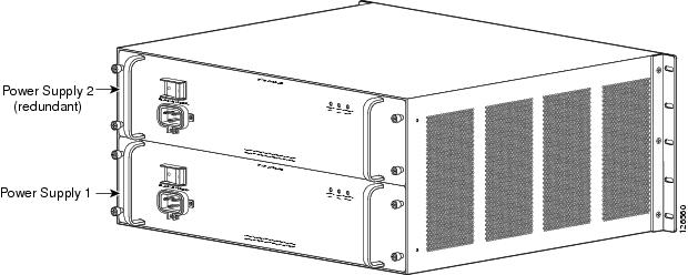
Table 1-5 Catalyst 6504-E Switch Features
|
|
|
Chassis |
Four horizontal slots. Slots are numbered from 1 (top) to 4 (bottom). |
Power supplies |
•Supports one or two power supplies. The following power supplies are supported: –PWR-2700-AC/4 (2700 W AC-input power supply) –PWR-2700-DC/4 (2700 W DC-input power supply) Note For information and specifications for each of the supported power supplies, refer to Appendix A, "Power Supply Specifications," in the Catalyst 6500 Series Switches Installation Guide. •Installed power supplies can be both AC-input, both DC-input, or one AC-input and one DC-input. Power supplies can be configured in either redundant or nonredundant mode. •All Catalyst 6500 series AC-input power supplies require single-phase source AC. Source AC can be out of phase between multiple power supplies or multiple AC-power plugs on the same power supply because all AC power supply inputs are isolated. •Single power supplies are installed in the lower power supply bay. The second power supply is installed in the upper power supply bay. |
Supervisor engines |
•Supports Supervisor Engine 2, Supervisor Engine 32, Supervisor Engine 32 PISA, Supervisor Engine 720, Supervisor Engine 720-10GE, and Supervisor Engine 2T. –Supervisor engines are installed in slot 1 and slot 2. –Supervisor Engine 720, Supervisor Engine 720-10GE, and Supervisor Engine 2T have built-in switching fabric. Switch Fabric Modules (WS-C6500-SFM and WS-X6500-SFM2) are not supported by those supervisor engines. –Supervisor Engine 32 and Supervisor Engine 32 PISA do not support the Switch Fabric Modules ((WS-C6500-SFM and WS-X6500-SFM2). •The uplink ports are fully functional on the redundant supervisor engine when it is in standby mode. Note In systems with redundant supervisor engines, both supervisor engines must be the same model and have the same daughter card configurations. Each supervisor engine must have the resources to run the switch on its own, which means all supervisor engine resources are duplicated. Identical supervisor engine memory configurations are recommended, but are not required as long as the supervisor engine with the smaller memory configuration is sufficient to run the configured features of the switch. Additionally, each supervisor engine must have its own flash device and console port connections. |
Modules |
•Chassis supports up to three Catalyst 6500 series modules. •Chassis does not support the WS-C6500-SFM and WS-X6500-SFM2 Switch Fabric Modules. •Some Catalyst 6500 series modules: –Are not supported –Require that you install a Supervisor Engine 720 or Supervisor Engine 2T –Have chassis slot restrictions –Require a specific software release level Check your software release notes for specific information on module support and restrictions. |
Table 1-6 Catalyst 6504-E Switch Specifications
|
|
|
|
|
|
Temperature, operating |
Certified for operation: 32° to 104°F (0° to 40°C) Designed and tested for operation: 32° to 130°F (0° to 55°C) Note The Catalyst 6500 series switches are equipped with internal air temperature sensors that are triggered at 104°F (40°C) generating a minor alarm and at 131°F (55°C) generating a major alarm. |
Temperature, nonoperating and storage |
-4° to 149°F (-20° to 65°C) |
Thermal transition |
0.5°C per minute (hot to cold) 0.33°C per minute (cold to hot) |
Humidity (RH), ambient (noncondensing) operating |
10% to 85% |
Humidity (RH), ambient (noncondensing) nonoperating and storage |
5% to 95% |
Altitude, operating |
Certified for operation: 0 to 6500 feet (0 to 2000 m) Designed and tested for operation: -200 to 10,000 feet (-60 to 3000 m) |
|
|
|
Dimensions (H x W x D) |
•8.7 x 17.5 x 21.6 in. (22.09 x 44.45 x 54.86 cm). •Chassis requires 5 RU. •Chassis can be mounted in equipment racks that meet ANSI/EIA 310-D and ETS 300-119 standards. |
Weight |
•Chassis only: 27 lb (12.25 kg). •Chassis fully configured with 2 supervisor engines, 2 modules, and 2 AC-input power supplies: 97 lb (43.99 kg). |
|
|
FAN-MOD-4HS—300 CFM Note To maintain proper air circulation through the Catalyst switch chassis, we recommend that you maintain a minimum 6-inch (15 cm) separation between a wall and the chassis air intake or a wall and the chassis air exhaust. You should also allow a minimum separation of 12 inches (30.5 cm) between the hot air exhaust on one chassis and the air intake on another chassis. Failure to maintain adequate air space can cause the chassis to overheat and the system to fail. On Catalyst chassis in which the airflow is from front to back, the chassis may be placed side-by-side. |
Catalyst 6506 Switch
The Catalyst 6506 switch is a 6-slot horizontal chassis. Figure 1-7 shows a front view of the chassis. Table 1-7 provides a description of the major switch features. Table 1-8 lists the specifications of the Catalyst 6506 switch chassis.
Figure 1-7 Catalyst 6506 Switch
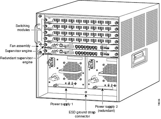
Table 1-7 Catalyst 6506 Switch Features
|
|
|
Chassis |
Six horizontal slots. Slots are numbered from 1 (top) to 6 (bottom). |
Power supplies |
•Supports one or two power supplies. The following power supplies are supported: –WS-CAC-1000W (1000 W AC-input power supply) –WS-CAC-1300W (1300 W AC-input power supply) –WS-CDC-1300W (1300 W DC-input power supply) –WS-CAC-2500W (2500 W AC-input power supply) –WS-CDC-2500W (2500 W DC-input power supply) –WS-CAC-3000W (3000 W AC-input power supply) –WS-CAC-4000W-US (4000 W AC-input power supply) –WS-CAC-4000W-INT (4000 W AC-input power supply) –PWR-4000-DC (4000 W DC-input power supply) –WS-CAC-6000W (6000 W AC-input power supply) –WS-CAC-8700W (8700 W AC-input power supply) Note The 6000 W and the 8700 W AC-input power supplies are limited to 4500 W maximum output when installed in the Catalyst 6506 chassis. Note For information and specifications for each of the supported power supplies, refer to Appendix A, "Power Supply Specifications," in the Catalyst 6500 Series Switches Installation Guide. •Installed power supplies can be of different wattage ratings. Installed power supplies can also be both AC-input, both DC-input, or one AC-input and one DC-input. Power supplies can be configured in either redundant or nonredundant mode. •All Catalyst 6500 series AC-input power supplies require single-phase source AC. Source AC can be out of phase between multiple power supplies or multiple AC-power plugs on the same power supply because all AC power supply inputs are isolated. •Single power supplies are installed in the left power supply bay. The second power supply is installed in the right power supply bay. •You must install a 2500 W or higher capacity power supply when using the Supervisor Engine 32 or the Supervisor Engine 720 and the high-speed fan tray. |
Supervisor engines |
•Supports Supervisor Engine 2, Supervisor Engine 32, Supervisor Engine 32 PISA, Supervisor Engine 720, and Supervisor Engine 720-10GE. –Supervisor Engine 2 is installed in slot 1 or slot 2. –Supervisor Engine 32, Supervisor Engine 32 PISA, Supervisor Engine 720, and Supervisor Engine 720-10GE are installed in slot 5 or slot 6. –Supervisor Engine 32, Supervisor Engine 32 PISA, Supervisor Engine 720, and Supervisor Engine 720-10GE all require the high-speed fan tray (WS-C6K-6SLOT-FAN2) be installed in the chassis. You must also install a 2500 W or higher capacity power supply in the chassis to power the high-speed fan tray. Note The 2500 W power supply, when supporting the high-speed fan tray, can be powered from either 120 VAC or 220 VAC. –Supervisor Engine 720 and Supervisor Engine 720-10GE have built-in switching fabric. Switch Fabric Modules (WS-C6500-SFM and WS-X6500-SFM2) are not supported by Supervisor Engine 720 and Supervisor Engine 720-10GE and cannot be installed in the same chassis. –Supervisor Engine 32 and Supervisor Engine 32 PISA do not support the Switch Fabric Modules (WS-C6500-SFM and WS-X6500-SFM2). •The uplink ports are fully functional on the redundant supervisor engine in standby mode. Note In systems with redundant supervisor engines, both supervisor engines must be the same model and have the same daughter card configurations. Each supervisor engine must have the resources to run the switch on its own, which means all supervisor engine resources are duplicated. Identical supervisor engine memory configurations are recommended, but are not required as long as the supervisor engine with the smaller memory configuration is sufficient to run the configured features of the switch. Additionally, each supervisor engine must have its own flash device and console port connections. |
Modules |
•Chassis supports up to five Catalyst 6500 series modules. •WS-C6500-SFM and WS-X6500-SFM2 Switch Fabric Modules must be installed in slot 5 or slot 6. •Some Catalyst 6500 series modules: –Are not supported –Require that you install a Supervisor Engine 720 –Have chassis slot restrictions –Require a specific software release level Check your software release notes for specific information on supported modules. |
Table 1-8 Catalyst 6506 Switch Specifications
|
|
|
|
|
|
Temperature, operating |
Certified for operation: 32° to 104°F (0° to 40°C) Designed and tested for operation: 32° to 130°F (0° to 55°C) Note The Catalyst 6500 series switches are equipped with internal air temperature sensors that are triggered at 104°F (40°C) generating a minor alarm and at 131°F (55°C) generating a major alarm. |
Temperature, nonoperating and storage |
-4° to 149°F (-20° to 65°C) |
Thermal transition |
0.5°C per minute (hot to cold) 0.33°C per minute (cold to hot) |
Humidity (RH), ambient (noncondensing) operating |
10% to 90% |
Humidity (RH), ambient (noncondensing) nonoperating and storage |
5% to 95% |
Altitude, operating |
Certified for operation: 0 to 6500 feet (0 to 2000 m) Designed and tested for operation: -200 to 10,000 feet (-60 to 3000 m) |
|
|
|
Dimensions (H x W x D) |
•20.1 x 17.2 x 18.1 in. (51.1 x 43.7 x 46.0 cm). •Chassis depth including cable guide is 21.64 in. (55.0 cm). •Chassis requires 12 RU. •Chassis can be mounted in equipment racks that meet ANSI/EIA 310-D and ETS 300-119 standards. |
Weight |
•Chassis only: 45 lb (20.4 kg). •Chassis fully configured with 1 supervisor engine, 5 switching modules, and 2 power supplies: 156.6 lb (71.0 kg). |
|
|
•WS-C6K-6SLOT-FAN (Standard fan tray)—227 CFM. •WS-C6K-6SLOT-FAN2 (Optional high-speed fan tray)—420 CFM. Note To maintain proper air circulation through the Catalyst switch chassis, we recommend that you maintain a minimum 6-inch (15 cm) separation between a wall and the chassis air intake or a wall and the chassis air exhaust. You should also allow a minimum separation of 12 inches (30.5 cm) between the hot air exhaust on one chassis and the air intake on another chassis. Failure to maintain adequate air space can cause the chassis to overheat and the system to fail. On Catalyst chassis in which the airflow is from front to back, the chassis may be placed side-by-side. |
Catalyst 6506-E Switch
The Catalyst 6506-E switch is an enhanced version of the Catalyst 6506 chassis. Figure 1-8 shows a front view of the chassis. Table 1-9 provides a description of the major switch features. Table 1-10 lists the specifications of the Catalyst 6506-E switch chassis.
Figure 1-8 Catalyst 6506-E Switch
Table 1-9 Catalyst 6506-E Switch Features
|
|
|
Chassis |
Six horizontal slots. Slots are numbered from 1 (top) to 6 (bottom). |
Power supplies |
•Supports one or two power supplies. The following power supplies are supported: –WS-CAC-2500W (2500 W AC-input power supply) –WS-CDC-2500W (2500 W DC-input power supply) –WS-CAC-3000W (3000 W AC-input power supply) –WS-CAC-4000W-US (4000 W AC-input power supply) –WS-CAC-4000W-INT (4000 W AC-input power supply) –PWR-4000-DC (4000 W DC-input power supply) –WS-CAC-6000W (6000 W AC-input power supply) –WS-CAC-8700W-E (8700 W AC-input power supply) Note For information and specifications for each of the supported power supplies, refer to Appendix A, "Power Supply Specifications," in the Catalyst 6500 Series Switches Installation Guide. •Installed power supplies can be of different wattage ratings. Installed power supplies can also be both AC-input, both DC-input, or one AC-input and one DC-input. Power supplies can be configured in either redundant or nonredundant mode. •All Catalyst 6500 series AC-input power supplies require single-phase source AC. Source AC can be out of phase between multiple power supplies or multiple AC-power plugs on the same power supply because all AC power supply inputs are isolated. •The Supervisor Engine 2T requires a 3000 W or greater power supply to operate. •Single power supplies are installed in the left power supply bay. The second power supply is installed in the right power supply bay. |
Supervisor engines |
•Supports Supervisor Engine 2, Supervisor Engine 32, Supervisor Engine 32 PISA, Supervisor Engine 720, Supervisor Engine 720-10GE, and Supervisor Engine 2T. –Supervisor Engine 2 is installed in slot 1 and slot 2. –Supervisor Engine 32, Supervisor Engine 32 PISA, Supervisor Engine 720, Supervisor Engine 720-10GE, and Supervisor Engine 2T are installed in slot 5 and slot 6. –Supervisor Engine 720, Supervisor Engine 720-10GE, and Supervisor Engine 2T have built-in switching fabric; Switch Fabric Modules (WS-C6500-SFM and WS-X6500-SFM2) are not supported. –Supervisor Engine 32 and Supervisor Engine 32 PISA do not support the Switch Fabric Modules ((WS-C6500-SFM and WS-X6500-SFM2). •The uplink ports are fully functional on the redundant supervisor engine in standby mode. Note In systems with redundant supervisor engines, both supervisor engines must be the same model and have the same daughter card configurations. Each supervisor engine must have the resources to run the switch on its own, which means all supervisor engine resources are duplicated. Identical supervisor engine memory configurations are recommended, but are not required as long as the supervisor engine with the smaller memory configuration is sufficient to run the configured features of the switch. Additionally, each supervisor engine must have its own flash device and console port connections. |
Modules |
•Chassis supports up to five Catalyst 6500 series modules. •WS-C6500-SFM and WS-X6500-SFM2 Switch Fabric Modules must be installed in slot 5 or slot 6. •Some Catalyst 6500 series modules: –Are not supported –Require that you install a Supervisor Engine 720 –Have chassis slot restrictions –Require a specific software release level Check your software release notes for specific information on module support and restrictions. |
Table 1-10 Catalyst 6506-E Switch Specifications
|
|
|
|
|
|
Temperature, operating |
Certified for operation: 32° to 104°F (0° to 40°C) Designed and tested for operation: 32° to 130°F (0° to 55°C) Note The Catalyst 6500 series switches are equipped with internal air temperature sensors that are triggered at 104°F (40°C) generating a minor alarm and at 131°F (55°C) generating a major alarm. |
Temperature, nonoperating and storage |
-4° to 149°F (-20° to 65°C) |
Thermal transition |
0.5°C per minute (hot to cold) 0.33°C per minute (cold to hot) |
Humidity (RH), ambient (noncondensing) operating |
10% to 90% |
Humidity (RH), ambient (noncondensing) nonoperating and storage |
5% to 95% |
Altitude, operating |
Certified for operation: 0 to 6500 feet (0 to 2000 m) Designed and tested for operation: -200 to 10,000 feet (-60 to 3000 m) |
|
|
|
Dimensions (H x W x D) |
•19.2 x 17.5 x 18.2 in. (48.8 x 44.5 x 46.0 cm). •Chassis depth including cable guide is 21.64 in. (55.0 cm). •Chassis requires 12 RU. •Chassis can be mounted in equipment racks that meet ANSI/EIA 310-D and ETS 300-119 standards. |
Weight |
Chassis only: 45 lb (20.41 kg). Chassis fully configured with 1 supervisor engine, 5 switching modules, and 2 power supplies: 159 lb (72.3 kg). |
|
|
WS-C6506-E-FAN—564 CFM. Note To maintain proper air circulation through the Catalyst switch chassis, we recommend that you maintain a minimum 6-inch (15 cm) separation between a wall and the chassis air intake or a wall and the chassis air exhaust. You should also allow a minimum separation of 12 inches (30.5 cm) between the hot air exhaust on one chassis and the air intake on another chassis. Failure to maintain adequate air space can cause the chassis to overheat and the system to fail. On Catalyst chassis in which the airflow is from front to back, the chassis may be placed side-by-side. |
Catalyst 6509 Switch
The Catalyst 6509 switch is a 9-slot horizontal chassis. Figure 1-9 shows a front view of the chassis. Table 1-11 provides a description of the major switch features. Table 1-12 lists the specifications of the Catalyst 6509 switch chassis.
Figure 1-9 Catalyst 6509 Switch
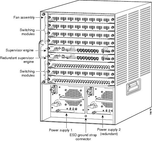
Table 1-11 Catalyst 6509 Switch Features
|
|
|
Chassis |
Nine horizontal slots. Slots are numbered from 1 (top) to 9 (bottom). |
Power supplies |
•Supports one or two power supplies. The following power supplies are supported: –WS-CAC-1000W (1000 W AC-input power supply) –WS-CAC-1300W (1300 W AC-input power supply) –WS-CDC-1300W (1300 W DC-input power supply) –WS-CAC-2500W (2500 W AC-input power supply) –WS-CDC-2500W (2500 W DC-input power supply) –WS-CAC-3000W (3000 W AC-input power supply) –WS-CAC-4000W-US (4000 W AC-input power supply) –WS-CAC-4000W-INT (4000 W AC-input power supply) –PWR-4000-DC (4000 W DC-input power supply) –WS-CAC-6000W (6000 W AC-input power supply) –WS-CAC-8700W-E (8700 W AC-input power supply) Note The 6000 W and the 8700 W AC-input power supplies are limited to 4500 W maximum output when installed in the Catalyst 6509 chassis. Note For information and specifications for each of the supported power supplies, refer to Appendix A, "Power Supply Specifications," in the Catalyst 6500 Series Switches Installation Guide. •Installed power supplies can be of different wattage ratings. Installed power supplies can also be both AC-input, both DC-input, or one AC-input and one DC-input. Power supplies can be configured in either redundant or nonredundant mode. •All Catalyst 6500 series AC-input power supplies require single-phase source AC. Source AC can be out of phase between multiple power supplies or multiple AC-power plugs on the same power supply because all AC power supply inputs are isolated. •Single power supplies are installed in the left power supply bay. The second (redundant) power supply is installed in the right power supply bay. •You must install a 2500 W or higher capacity power supply when using the Supervisor Engine 32 or the Supervisor Engine 720 and the high-speed fan tray. |
Supervisor engines |
•Supports Supervisor Engine 2, Supervisor Engine 32, Supervisor Engine 32 PISA, Supervisor Engine 720, and Supervisor Engine 720-10GE. –Supervisor Engine 2 is installed in slot 1 and slot 2. –Supervisor Engine 32, Supervisor Engine 32 PISA, Supervisor Engine 720, and Supervisor Engine 720-10GE are installed in slot 5 and slot 6. –Supervisor Engine 32, Supervisor Engine 32 PISA, Supervisor Engine 720, and Supervisor Engine 720-10GE require that the high-speed fan tray be installed in the chassis. You must also install a 2500 W or higher capacity power supply in the chassis to power the high-speed fan tray. Note The 2500 W power supply, when supporting the high-speed fan tray, can be powered from either 120 VAC or 220 VAC. –Supervisor Engine 720 and Supervisor Engine 720-10GE have built-in switching fabric. Switch Fabric Modules (WS-C6500-SFM and WS-X6500-SFM2) are not supported by Supervisor Engine 720 and Supervisor Engine 720-10GE and cannot be installed in the same chassis. –Supervisor Engine 32 and Supervisor Engine 32 PISA do not support the Switch Fabric Modules (WS-C6500-SFM and WS-X6500-SFM2). •The uplink ports are fully functional on all redundant supervisor engine models when they are in standby mode. Note In systems with redundant supervisor engines, both supervisor engines must be the same model and have the same daughter card configurations. Each supervisor engine must have the resources to run the switch on its own, which means all supervisor engine resources are duplicated. Identical supervisor engine memory configurations are recommended, but are not required as long as the supervisor engine with the smaller memory configuration is sufficient to run the configured features of the switch. Additionally, each supervisor engine must have its own flash device and console port connections. |
Modules |
•Chassis supports up to eight Catalyst 6500 series modules. •WS-C6500-SFM and WS-X6500-SFM2 Switch Fabric Modules must be installed in slot 5 or slot 6. •Some Catalyst 6500 series modules: –Are not supported –Require that you install a Supervisor Engine 720 –Have chassis slot restrictions –Require a specific software release level Check your software release notes for specific information on supported modules. |
Table 1-12 Catalyst 6509 Switch Specifications
|
|
|
|
|
|
Temperature, operating |
Certified for operation: 32° to 104°F (0° to 40°C) Designed and tested for operation: 32° to 130°F (0° to 55°C) Note The Catalyst 6500 series switches are equipped with internal air temperature sensors that are triggered at 104°F (40°C) generating a minor alarm and at 131°F (55°C) generating a major alarm. |
Temperature, ambient nonoperating and storage |
-20° to 65°C (-4° to 149°F) |
Thermal transition |
0.5°C per minute (hot to cold) 0.33°C per minute (cold to hot) |
Humidity (RH), ambient (noncondensing) operating |
10% to 90% |
Humidity (RH), ambient (noncondensing) nonoperating and storage |
5% to 95% |
Altitude, operating |
Certified for operation: 0 to 6500 feet (0 to 2000 m) Designed and tested for operation: -200 to 10,000 feet (-60 to 3000 m) |
Physical Characteristics |
|
Dimensions (H x W x D) |
•25.2 x 17.2 x 18.4 in. (64.0 x 43.7 x 46.7 cm). •Chassis depth including cable guide is 21.64 in. (55.0 cm). •Chassis requires 15 RU. •Chassis can be mounted in equipment racks that meet ANSI/EIA 310-D and ETS 300-119 standards. |
Weight |
Chassis only: 55 lb (24.9 kg). Chassis fully configured with 1 supervisor engine, 8 switching modules, and 2 power supplies: 194.5 lb (88.2 kg). |
|
|
•WS-C6K-9SLOT-FAN (Standard fan tray)—340 CFM •WS-C6K-9SLOT-FAN2 (Optional high-speed fan tray)—630 CFM Note To maintain proper air circulation through the Catalyst switch chassis, we recommend that you maintain a minimum 6-inch (15 cm) separation between a wall and the chassis air intake or a wall and the chassis air exhaust. You should also allow a minimum separation of 12 inches (30.5 cm) between the hot air exhaust on one chassis and the air intake on another chassis. Failure to maintain adequate air space can cause the chassis to overheat and the system to fail. On Catalyst chassis in which the airflow is from front to back, the chassis may be placed side-by-side. |
Catalyst 6509-E Switch
The Catalyst 6509-E switch is an enhanced version of the Catalyst 6509 chassis. Figure 1-10 shows a front view of the chassis. Table 1-13 provides a description of the major switch features. Table 1-14 lists the specifications of the Catalyst 6509-E switch chassis.
Figure 1-10 Catalyst 6509-E Switch

Table 1-13 Catalyst 6509-E Switch Features
|
|
|
Chassis |
Nine horizontal slots. Slots are numbered from (1) top to (9) bottom. |
Power supplies |
•Supports one or two power supplies. The following power supplies are supported: –WS-CAC-2500W (2500 W AC-input power supply) –WS-CDC-2500W (2500 W DC-input power supply) –WS-CAC-3000W (3000 W AC-input power supply) –WS-CAC-4000W-US (4000 W AC-input power supply) –WS-CAC-4000W-INT (4000 W AC-input power supply) –PWR-4000-DC (4000 W DC-input power supply) –WS-CAC-6000W (6000 W AC-input power supply) –WS-CAC-8700W-E (8700 W AC-input power supply) Note For information and specifications for each of the supported power supplies, refer to Appendix A, "Power Supply Specifications," in the Catalyst 6500 Series Switches Installation Guide. •Installed power supplies can be of different wattage ratings. Installed power supplies can also be both AC-input, both DC-input, or one AC-input and one DC-input. Power supplies can be configured in either redundant or nonredundant mode. •Supervisor Engine 2T requires a 3000 W or greater power supply to operate. •All Catalyst 6500 series AC-input power supplies require single-phase source AC. Source AC can be out of phase between multiple power supplies or multiple AC-power plugs on the same power supply because all AC power supply inputs are isolated. |
Supervisor engines |
•Supports Supervisor Engine 2, Supervisor Engine 32, Supervisor Engine 32 PISA, Supervisor Engine 720, Supervisor Engine 720-10GE, and Supervisor Engine 2T. –Supervisor Engine 2 is installed in slot 1 and slot 2. –Supervisor Engine 32, Supervisor Engine 32 PISA, Supervisor Engine 720, Supervisor Engine 720-10GE, and Supervisor Engine 2T are installed in slot 5 and slot 6. –Supervisor Engine 720, Supervisor Engine 720-10GE, and Supervisor Engine 2T have built-in switching fabric; Switch Fabric Modules (WS-C6500-SFM and WS-X6500-SFM2) are not supported. –Supervisor Engine 32 and Supervisor Engine 32 PISA do not support the Switch Fabric Modules (WS-C6500-SFM and WS-X6500-SFM2). •The uplink ports are fully functional on all redundant supervisor engine models when they are in standby mode. Note In systems with redundant supervisor engines, both supervisor engines must be the same model and have the same daughter card configurations. Each supervisor engine must have the resources to run the switch on its own, which means all supervisor engine resources are duplicated. Identical supervisor engine memory configurations are recommended, but are not required as long as the supervisor engine with the smaller memory configuration is sufficient to run the configured features of the switch. Additionally, each supervisor engine must have its own flash device and console port connections. |
Modules |
•Chassis supports up to eight Catalyst 6500 series modules. •WS-C6500-SFM and WS-X6500-SFM2 Switch Fabric Modules must be installed in slot 5 or slot 6. •Some Catalyst 6500 series modules: –Are not supported –Require that you install a Supervisor Engine 720 or Supervisor Engine 2T –Have chassis slot restrictions –Require a specific software release level Note Check your software release notes for specific information on module support and restrictions. |
Table 1-14 Catalyst 6509-E Switch Specifications
|
|
|
|
|
|
Temperature, operating |
Certified for operation: 32° to 104°F (0° to 40°C) Designed and tested for operation: 32° to 130°F (0° to 55°C) Note The Catalyst 6500 series switches are equipped with internal air temperature sensors that are triggered at 104°F (40°C) generating a minor alarm and at 131°F (55°C) generating a major alarm. |
Temperature, nonoperating and storage |
-4° to 149°F (-20° to 65°C) |
Thermal transition |
0.5°C per minute (hot to cold) 0.33°C per minute (cold to hot) |
Humidity (RH), ambient (noncondensing) operating |
10% to 90% |
Humidity (RH), ambient (noncondensing) nonoperating and storage |
5% to 95% |
Altitude, operating |
Certified for operation: 0 to 6500 feet (0 to 2000 m) Designed and tested for operation: -200 to 10,000 feet (-60 to 3000 m) |
|
|
|
Dimensions (H x W x D) |
•24.5 x 17.5 x 18.2 in. (62.2 x 44.5 x 46.0 cm). •Chassis depth including cable guide is 21.64 in. (55.0 cm). •Chassis requires 15 RU. •Chassis can be mounted in equipment racks that meet ANSI/EIA 310-D and ETS 300-119 standards. |
Weight |
Chassis only: 55 lb (24.9 kg). Chassis fully configured with 1 supervisor engine, 8 switching modules, and 2 power supplies: 135 lb (61.2 kg). |
|
|
WS-C6509-E-FAN—846 CFM Note To maintain proper air circulation through the Catalyst switch chassis, we recommend that you maintain a minimum 6-inch (15 cm) separation between a wall and the chassis air intake or a wall and the chassis air exhaust. You should also allow a minimum separation of 12 inches (30.5 cm) between the hot air exhaust on one chassis and the air intake on another chassis. Failure to maintain adequate air space can cause the chassis to overheat and the system to fail. On Catalyst chassis in which the airflow is from front to back, the chassis may be placed side-by-side. |
Catalyst 6509-NEB Switch
The Catalyst 6509-NEB switch is a 9-slot vertical chassis. Figure 1-11 shows a front view of the chassis. Table 1-15 provides a description of the major switch features. Table 1-16 lists the specifications of the Catalyst 6509-NEB switch chassis.
Figure 1-11 Catalyst 6509-NEB Switch
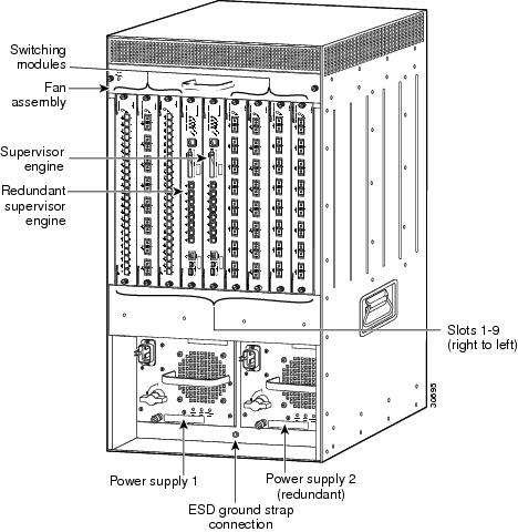
Table 1-15 Catalyst 6509-NEB Switch Features
|
|
|
Chassis |
Nine vertical slots. Slots are numbered from 1 (right) to 9 (left). |
Power supplies |
•Supports one or two power supplies. The following power supplies are supported: –WS-CAC-2500W (2500 W AC-input power supply) –WS-CDC-2500W (2500 W DC-input power supply) –WS-CAC-3000W (3000 W AC-input power supply) –WS-CAC-4000W-US (4000 W AC-input power supply) –WS-CAC-4000W-INT (4000 W AC-input power supply) –PWR-4000-DC (4000 W DC-input power supply) –WS-CAC-6000W (6000 W AC-input power supply) –WS-CAC-8700W-E (8700 W AC-input power supply) Note The 6000 W and the 8700 W AC-input power supplies are limited to 4500 W maximum output when installed in the Catalyst 6509-NEB chassis. Note For information and specifications for each of the supported power supplies, refer to Appendix A, "Power Supply Specifications," in the Catalyst 6500 Series Switches Installation Guide. •Installed power supplies can be of different wattage ratings. Installed power supplies can also be both AC-input, both DC-input, or one AC-input and one DC-input. Power supplies can be configured in either redundant or nonredundant mode. •All Catalyst 6500 series AC-input power supplies require single-phase source AC. Source AC can be out of phase between multiple power supplies or multiple AC-power plugs on the same power supply because all AC power supply inputs are isolated. •Single power supplies are installed in the left power supply bay. The second power supply is installed in the right power supply bay. |
Supervisor engines |
•Supports Supervisor Engine 2, Supervisor Engine 32, Supervisor Engine 32 PISA, Supervisor Engine 720, and Supervisor Engine 720-10GE. –Supervisor Engine 2 is installed in slot 1 or slot 2. –Supervisor Engine 32 is installed in slot 5 or slot 6. •Supervisor Engine 32, Supervisor Engine 32 PISA, Supervisor Engine 720, and Supervisor Engine 720-10GE are supported if the WS-6509-NEB-UPGRD kit is installed. –Supervisor Engine 32, Supervisor Engine 32 PISA, Supervisor Engine 720, and Supervisor Engine 720-10GE. are installed in slot 5 or slot 6. –Supervisor Engine 720 and Supervisor Engine 720-10GE have built-in switching fabric. Switch Fabric Modules (WS-C6500-SFM and WS-X6500-SFM2) are not supported by Supervisor Engine 720 and cannot be installed in the same chassis. –Supervisor Engine 32 and Supervisor Engine 32 PISA do not support the Switch Fabric Modules ((WS-C6500-SFM and WS-X6500-SFM2). •The uplink ports are fully functional on all redundant supervisor engine models when they are in standby mode. Note In systems with redundant supervisor engines, both supervisor engines must be the same model and have the same daughter card configurations. Each supervisor engine must have the resources to run the switch on its own, which means all supervisor engine resources are duplicated. Identical supervisor engine memory configurations are recommended, but are not required as long as the supervisor engine with the smaller memory configuration is sufficient to run the configured features of the switch. Additionally, each supervisor engine must have its own flash device and console port connections. |
Modules |
•Chassis supports up to eight Catalyst 6500 series modules. •WS-C6500-SFM and WS-X6500-SFM2 Switch Fabric Modules must be installed in slot 5 or slot 6. •Some Catalyst 6500 series modules: –Are not supported –Require that you install a Supervisor Engine 720 –Have chassis slot restrictions –Require a specific software release level Note Check your software release notes for specific information on module support and restrictions. |
Table 1-16 Catalyst 6509-NEB Switch Specifications
|
|
|
|
|
|
Temperature, operating |
Certified for operation: 32° to 104°F (0° to 40°C) Designed and tested for operation: 32° to 130°F (0° to 55°C) Note The Catalyst 6500 series switches are equipped with internal air temperature sensors that are triggered at 104°F (40°C) generating a minor alarm and at 131°F (55°C) generating a major alarm. |
Temperature, nonoperating and storage |
-4° to 149°F (-20° to 65°C) |
Thermal transition |
0.5°C per minute (hot to cold) 0.33°C per minute (cold to hot) |
Humidity (RH), ambient (noncondensing) operating |
10% to 90% |
Humidity (RH), ambient (noncondensing) nonoperating and storage |
5% to 95% |
Altitude, operating |
Certified for operation: 0 to 6500 feet (0 to 2000 m) Designed and tested for operation: -200 to 10,000 feet (-60 to 3000 m) |
|
|
|
Dimensions (H x W x D) |
•33.3 x 17.2 x 18.1 in. (84.6 x 43.7 x 46.0 cm). •Chassis requires 20 RU. •Chassis can be mounted in equipment racks that meet ANSI/EIA 310-D and ETS 300-119 standards. |
Weight |
Chassis only: 55 lb (24.9 kg).
Chassis fully configured with 1 supervisor engine, 8 switching modules, and 2 power supplies: 135 lb (61.2 kg). |
|
|
•WS-C6509-NEB-FAN (standard fan tray)—294 CFM •Optional high-speed fan tray1 —630 CFM Note To maintain proper air circulation through the Catalyst switch chassis, we recommend that you maintain a minimum 6-inch (15 cm) separation between a wall and the chassis air intake or a wall and the chassis air exhaust. You should also allow a minimum separation of 12 inches (30.5 cm) between the hot air exhaust on one chassis and the air intake on another chassis. Failure to maintain adequate air space can cause the chassis to overheat and the system to fail. On Catalyst chassis in which the airflow is from front to back, the chassis may be placed side-by-side. |
Catalyst 6509-NEB-A Switch
The Catalyst 6509-NEB-A switch is a 9-slot vertical chassis. Figure 1-12 shows a front view of the chassis. Table 1-17 provides a description of the major switch features. Table 1-18 lists the specifications of the Catalyst 6509-NEB-A switch chassis.
Figure 1-12 Catalyst 6509-NEB-A Switch Chassis
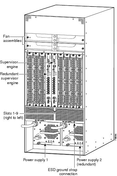
Table 1-17 Catalyst 6509-NEB-A Switch Features
|
|
|
Chassis |
Nine vertical slots. Slots are numbered from 1 (right) to 9 (left). |
Power supplies |
•Supports one or two power supplies. The following power supplies are supported: –WS-CAC-2500W (2500 W AC-input power supply) –WS-CDC-2500W (2500 W DC-input power supply) –WS-CAC-3000W (3000 W AC-input power supply) –WS-CAC-4000W-US (4000 W AC-input power supply) –WS-CAC-4000W-INT (4000 W AC-input power supply) –PWR-4000-DC (4000 W DC-input power supply) –WS-CAC-6000W (6000 W AC-input power supply) –WS-CAC-8700W-E (8700 W AC-input power supply) Note The 6000 W and the 8700 W AC-input power supplies are limited to 4500 W maximum output when installed in the Catalyst 6509-NEB-A chassis. Note For information and specifications for each of the supported power supplies, refer to Appendix A, "Power Supply Specifications," in the Catalyst 6500 Series Switches Installation Guide. •Installed power supplies can be of different ratings. Installed power supplies can also be both AC-input, both DC-input, or one AC-input and one DC-input. Power supplies can be configured in either redundant or nonredundant mode. •All Catalyst 6500 series AC-input power supplies require single-phase source AC. Source AC can be out of phase between multiple power supplies or multiple AC-power plugs on the same power supply because all AC power supply inputs are isolated. |
Supervisor engines |
•Supports Supervisor Engine 2, Supervisor Engine 32, Supervisor Engine 32 PISA, Supervisor Engine 720, and Supervisor Engine 720-10GE. –Supervisor Engine 2 is installed in slot 1 and slot 2. –Supervisor Engine 32, Supervisor Engine 32 PISA, Supervisor Engine 720, and Supervisor Engine 720-10GE are installed in slot 5 and slot 6. –Supervisor Engine 720 and Supervisor Engine 720-10GE have built-in switching fabric. Switch Fabric Modules (WS-C6500-SFM and WS-X6500-SFM2) are not supported by Supervisor Engine 720 and Supervisor Engine 720-10GE and cannot be installed in the same chassis. –Supervisor Engine 32 and Supervisor Engine 32 PISA do not support the Switch Fabric Modules ((WS-C6500-SFM and WS-X6500-SFM2). •The uplink ports are fully functional on all redundant supervisor engine models when they are in standby mode. Note In systems with redundant supervisor engines, both supervisor engines must be the same model and have the same daughter card configurations. Each supervisor engine must have the resources to run the switch on its own, which means all supervisor engine resources are duplicated. Identical supervisor engine memory configurations are recommended, but are not required as long as the supervisor engine with the smaller memory configuration is sufficient to run the configured features of the switch. Additionally, each supervisor engine must have its own flash device and console port connections. |
Modules |
•Chassis supports up to eight Catalyst 6500 series modules. •WS-C6500-SFM and WS-X6500-SFM2 Switch Fabric Modules must be installed in slot 5 or slot 6. •Some Catalyst 6500 series modules: –Are not supported –Require that you install a Supervisor Engine 720 –Have chassis slot restrictions –Require a specific software release level Note Check your software release notes for specific information on module support and restrictions. |
Table 1-18 Catalyst 6509-NEB-A Switch Specifications
|
|
|
|
|
|
Temperature, operating |
Certified for operation: 32° to 104°F (0° to 40°C) Designed and tested for operation: 32° to 130°F (0° to 55°C) Note The Catalyst 6500 series switches are equipped with internal air temperature sensors that are triggered at 104°F (40°C) generating a minor alarm and at 131°F (55°C) generating a major alarm. |
Temperature, nonoperating and storage |
-4° to 149°F (-20° to 65°C) |
Thermal transition |
0.5°C per minute (hot to cold) 0.33°C per minute (cold to hot) |
Humidity (RH), ambient (noncondensing) operating |
10% to 90% |
Humidity (RH), ambient (noncondensing) nonoperating and storage |
5% to 95% |
Altitude, operating |
Certified for operation: 0 to 6500 feet (0 to 2000 m) Designed and tested for operation: -200 to 10,000 feet (-60 to 3000 m) |
|
|
|
Dimensions (H x W x D) |
•36.7 x 17.2 x 20.3 in. (93.1 x 43.7 x 51.6 cm). •Chassis requires 21 RU. •Chassis can be mounted in equipment racks that meet ANSI/EIA 310-D and ETS 300-119 standards. |
Weight |
Chassis only: 121 lb (54.9 kg). Chassis fully configured with 1 supervisor engine, 8 modules, 2 AC-input power supplies: 270 lb (122.47 kg). |
|
|
FAN-MOD-09 (high-speed fan tray)—760 CFM Note To maintain proper air circulation through the Catalyst switch chassis, we recommend that you maintain a minimum 6-inch (15 cm) separation between a wall and the chassis air intake or a wall and the chassis air exhaust. You should also allow a minimum separation of 12 inches (30.5 cm) between the hot air exhaust on one chassis and the air intake on another chassis. Failure to maintain adequate air space can cause the chassis to overheat and the system to fail. On Catalyst chassis in which the airflow is from front to back, the chassis may be placed side-by-side. |
Catalyst 6509-V-E Switch
The Catalyst 6509-V-E switch is a 9-slot vertical enhanced chassis. Figure 1-13 shows a front view of the chassis. Table 1-19 provides a description of the major switch features. Table 1-20 lists the specifications of the Catalyst 6509-V-E switch chassis.
Figure 1-13 Catalyst 6509-V-E Switch Chassis
Table 1-19 Catalyst 6509-V-E Switch Features
|
|
|
Chassis |
Nine vertical slots. Slots are numbered from 1 (right) to 9 (left). |
` |
•Supports one or two power supplies. The following power supplies are supported: –WS-CAC-2500W (2500 W AC-input power supply) –WS-CDC-2500W (2500 W DC-input power supply) –WS-CAC-3000W (3000 W AC-input power supply) –WS-CAC-4000W-US (4000 W AC-input power supply) –WS-CAC-4000W-INT (4000 W AC-input power supply) –PWR-4000-DC (4000 W DC-input power supply) –WS-CAC-6000W (6000 W AC-input power supply) –WS-CAC-8700W-E (8700 W AC-input power supply) Note For information and specifications for each of the supported power supplies, refer to Appendix A, "Power Supply Specifications," in the Catalyst 6500 Series Switches Installation Guide. •Installed power supplies can be of different ratings. Installed power supplies can also be both AC-input, both DC-input, or one AC-input and one DC-input. Power supplies can be configured in either redundant or nonredundant mode. •Supervisor Engine 2T requires a 3000 W or greater power supply to operate. •All Catalyst 6500 series AC-input power supplies require single-phase source AC. Source AC can be out of phase between multiple power supplies or multiple AC-power plugs on the same power supply because all AC power supply inputs are isolated. |
Supervisor engines |
•Supports Supervisor Engine 32, Supervisor Engine 32 PISA, Supervisor Engine 720, Supervisor Engine 720-10GE, and Supervisor Engine 2T. –Supervisor Engine 32, Supervisor Engine 32 PISA, Supervisor Engine 720, Supervisor Engine 720-10GE, and Supervisor Engine 2T are installed in slot 5 and slot 6. –Supervisor Engine 720, Supervisor Engine 720-10GE, and Supervisor Engine 2T have built-in switching fabric; Switch Fabric Modules are not supported. –Supervisor Engine 32 and Supervisor Engine 32 PISA do not support the Switch Fabric Modules ((WS-C6500-SFM and WS-X6500-SFM2). •The uplink ports are fully functional on all redundant supervisor engine models when they are in standby mode. Note In systems with redundant supervisor engines, both supervisor engines must be the same model and have the same daughter card configurations. Each supervisor engine must have the resources to run the switch on its own, which means all supervisor engine resources are duplicated. Identical supervisor engine memory configurations are recommended, but are not required as long as the supervisor engine with the smaller memory configuration is sufficient to run the configured features of the switch. Additionally, each supervisor engine must have its own flash device and console port connections. |
Modules |
•Chassis supports up to eight Catalyst 6500 series modules. •Some Catalyst 6500 series modules: –Are not supported –Require that you install a Supervisor Engine 720 –Have chassis slot restrictions –Require a specific software release level Note Check your software release notes for specific information on module support and restrictions. |
Table 1-20 Catalyst 6509-V-E Switch Specifications
|
|
|
|
|
|
Temperature, operating |
Certified for operation: 32° to 104°F (0° to 40°C) Designed and tested for operation: 32° to 130°F (0° to 55°C) Note The Catalyst 6500 series switches are equipped with internal air temperature sensors that are triggered at 104°F (40°C) generating a minor alarm and at 131°F (55°C) generating a major alarm. |
Temperature, nonoperating and storage |
-4° to 149°F (-20° to 65°C) |
Thermal transition |
0.5°C per minute (hot to cold) 0.33°C per minute (cold to hot) |
Humidity (RH), ambient (noncondensing) operating |
10% to 90% |
Humidity (RH), ambient (noncondensing) nonoperating and storage |
5% to 95% |
Altitude, operating |
Certified for operation: 0 to 6500 feet (0 to 2000 m) Designed and tested for operation: -200 to 10,000 feet (-60 to 3000 m) |
|
|
|
Dimensions (H x W x D) |
•36.7 x 17.2 x 20.3 in. (93.1 x 43.7 x 51.6 cm). •Chassis requires 21 RU. •Chassis can be mounted in equipment racks that meet ANSI/EIA 310-D and ETS 300-119 standards. |
Weight |
Chassis only: 121 lb (54.9 kg). Chassis fully configured with 1 supervisor engine, 8 modules, 2 AC-input power supplies: 270 lb (122.47 kg). |
|
|
WS-C6509-V-E-FAN (High-speed fan tray—760 CFM). Note To maintain proper air circulation through the Catalyst switch chassis, we recommend that you maintain a minimum 6-inch (15 cm) separation between a wall and the chassis air intake or a wall and the chassis air exhaust. You should also allow a minimum separation of 12 inches (30.5 cm) between the hot air exhaust on one chassis and the air intake on another chassis. Failure to maintain adequate air space can cause the chassis to overheat and the system to fail. On Catalyst chassis in which the airflow is from front to back, the chassis may be placed side-by-side. |
Catalyst 6513 Switch
The Catalyst 6513 switch is a 13-slot horizontal chassis. Figure 1-14 shows a front view of the chassis. Table 1-21 provides a description of the major switch features. Table 1-22 lists the specifications of the Catalyst 6513 switch chassis.
Figure 1-14 Catalyst 6513 Switch
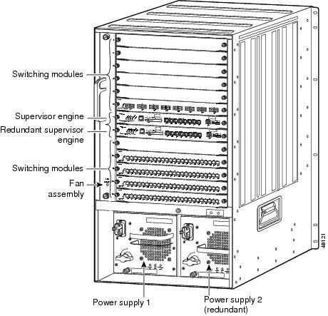
Table 1-21 Catalyst 6513 Switch Features
|
|
|
Chassis |
Thirteen horizontal slots. Slots are numbered from (1) top to (13) bottom. |
Power supplies |
•Supports one or two power supplies. The following power supplies are supported: –WS-CAC-2500W (2500 W AC-input power supply) –WS-CDC-2500W (2500 W DC-input power supply) –WS-CAC-3000W (3000 W AC-input power supply) –WS-CAC-4000W-US (4000 W AC-input power supply) –WS-CAC-4000W-INT (4000 W AC-input power supply) –PWR-4000-DC (4000 W DC-input power supply) –WS-CAC-6000W (6000 W AC-input power supply) –WS-CAC-8700W-E (8700 W AC-input power supply) Note For information and specifications for each of the supported power supplies, refer to Appendix A, "Power Supply Specifications," in the Catalyst 6500 Series Switches Installation Guide. •The 8700 W AC-input power supply is limited to 6000 W when it is installed in a Catalyst 6513 switch chassis. •Installed power supplies can be of different ratings. Installed power supplies can also be both AC-input, both DC-input, or one AC-input and one DC-input. Power supplies can be configured in either redundant or nonredundant mode. •All Catalyst 6500 series AC-input power supplies require single-phase source AC. Source AC can be out of phase between multiple power supplies or multiple AC-power plugs on the same power supply because all AC power supply inputs are isolated. •You must install a 2500 W or higher capacity power supply when using the Supervisor Engine 32 or the Supervisor Engine 720 and the high-speed fan tray. |
Supervisor engines |
•Supports Supervisor Engine 2, Supervisor Engine 32, Supervisor Engine 32 PISA, Supervisor Engine 720, and Supervisor Engine 720-10GE. –Supervisor Engine 2 is installed in slot 1 and slot 2. –Supervisor Engine 32, Supervisor Engine 32 PISA, Supervisor Engine 720, and Supervisor Engine 720-10GE are installed in slot 7 and slot 8. –Supervisor Engine 32, Supervisor Engine 32 PISA, Supervisor Engine 720, and Supervisor Engine 720-10GE require that you install the high-speed fan tray (WS-C6K-13SLT-FAN2) be installed in the chassis. You must also install a 2500 W or higher capacity power supply in the chassis to power the high-speed fan tray. –Supervisor Engine 720 and Supervisor Engine 720-10GE have built-in switching fabric. Switch Fabric Modules (WS-C6500-SFM and WS-X6500-SFM2) are not supported by Supervisor Engine 720 and Supervisor Engine 720-10GE and cannot be installed in the same chassis. –Supervisor Engine 32 and Supervisor Engine 32 PISA do not support the Switch Fabric Modules ((WS-C6500-SFM and WS-X6500-SFM2). •The uplink ports are fully functional on all redundant supervisor engine models when they are in standby mode. Note In systems with redundant supervisor engines, both supervisor engines must be the same model and have the same daughter card configurations. Each supervisor engine must have the resources to run the switch on its own, which means all supervisor engine resources are duplicated. Identical supervisor engine memory configurations are recommended, but are not required as long as the supervisor engine with the smaller memory configuration is sufficient to run the configured features of the switch. Additionally, each supervisor engine must have its own flash device and console port connections. |
Modules |
•Chassis supports up to 12 Catalyst 6500 series modules. •WS-C6500-SFM and WS-X6500-SFM2 Switch Fabric Modules must be installed in slot 7 or slot 8. •WS-X6748-SFP, WS-X6748-GE-TX, and WS-X6704-10GE modules are not supported in slots 2-8; they are supported in slots 9-13. –Slots 1-8 support a single fabric channel; slots 9-13 support dual fabric channels. •Some Catalyst 6500 series modules: –Are not supported –Require that you install a Supervisor Engine 720 –Have chassis slot restrictions –Require a specific software release level Note Check your software release notes for specific information on module support and restrictions. |
Table 1-22 Catalyst 6513 Switch Specifications
|
|
|
|
|
|
Temperature, operating |
Certified for operation: 32° to 104°F (0° to 40°C) Designed and tested for operation: 32° to 130°F (0° to 55°C) Note The Catalyst 6500 series switches are equipped with internal air temperature sensors that are triggered at 104°F (40°C) generating a minor alarm and at 131°F (55°C) generating a major alarm. |
Temperature, nonoperating and storage |
-4° to 149°F (-20° to 65°C) |
Thermal transition |
0.5°C per minute (hot to cold) 0.33°C per minute (cold to hot) |
Humidity (RH), ambient (noncondensing) operating |
10% to 90% |
Humidity (RH), ambient (noncondensing) nonoperating and storage |
5% to 95% |
Altitude, operating |
Certified for operation: 0 to 6500 feet (0 to 2000 m) Designed and tested for operation: -200 to 10,000 feet (-60 to 3000 m) |
|
|
|
Dimensions (H x W x D) |
•33.3 x 17.2 x 18.1 in. (84.6 x 43.7 x 46.0 cm). •Chassis requires 20 RU. •Chassis can be mounted in equipment racks that meet ANSI/EIA 310-D and ETS 300-119 standards. |
Weight |
Chassis fully configured with 2 supervisor engines, 11 switching modules, and 2 power supplies: 280 lb (127 kg). |
|
|
•WS-C6K-13SLOT-FAN (standard fan tray)—641 CFM •WS-C6K-13SLT-FAN2 (optional high-speed fan tray)—1090 CFM Note To maintain proper air circulation through the Catalyst switch chassis, we recommend that you maintain a minimum 6-inch (15 cm) separation between a wall and the chassis air intake or a wall and the chassis air exhaust. You should also allow a minimum separation of 12 inches (30.5 cm) between the hot air exhaust on one chassis and the air intake on another chassis. Failure to maintain adequate air space can cause the chassis to overheat and the system to fail. On Catalyst chassis in which the airflow is from front to back, the chassis may be placed side-by-side. |
Catalyst 6513-E Switch
The Catalyst 6513-E switch is an enhanced version of the Catalyst 6513 chassis. Figure 1-15 shows a front view of the chassis. Table 1-23 provides a description of the major switch features. Table 1-24 lists the specifications of the Catalyst 6513-E switch chassis.
Figure 1-15 Catalyst 6513-E Switch
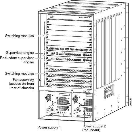
Table 1-23 Catalyst 6513-E Switch Features
|
|
|
Chassis |
Thirteen horizontal slots. Slots are numbered from (1) top to (13) bottom. |
Power supplies |
•Supports one or two power supplies. The following power supplies are supported: –WS-CDC-2500W (2500 W DC-input power supply) –WS-CAC-3000W (3000 W AC-input power supply) –WS-CAC-4000W-US (4000 W AC-input power supply) –WS-CAC-4000W-INT (4000 W AC-input power supply) –PWR-4000-DC (4000 W DC-input power supply) –WS-CAC-6000W (6000 W AC-input power supply) –PWR-6000-DC (6000 W DC-input power supply) –WS-CAC-8700W-E (8700 W AC-input power supply) Note For information and specifications for each of the supported power supplies, refer to Appendix A, "Power Supply Specifications," in the Catalyst 6500 Series Switches Installation Guide. •Installed power supplies can be of different ratings. Installed power supplies can also be both AC-input, both DC-input, or one AC-input and one DC-input. Power supplies can be configured in either redundant or nonredundant mode. •Supervisor Engine 2T requires a 3000 W or greater power supply to operate. •All Catalyst 6500 series AC-input power supplies require single-phase source AC. Source AC can be out of phase between multiple power supplies or multiple AC-power plugs on the same power supply because all AC power supply inputs are isolated. |
Supervisor engines |
•Supports Supervisor Engine 32, Supervisor Engine 720, Supervisor Engine 720-10GE, and Supervisor Engine 2T. –Supervisor Engine 32, Supervisor Engine 720, and Supervisor Engine 720-10GE are installed in slot 7 and slot 8. –Supervisor Engine 720, Supervisor Engine 720-10GE, and Supervisor Engine 2T have built-in switching fabric; Switch Fabric Modules (WS-C6500-SFM and WS-X6500-SFM2) are not supported. –Supervisor Engine 32 does not support the Switch Fabric Modules ((WS-C6500-SFM and WS-X6500-SFM2). •The uplink ports are fully functional on all redundant supervisor engine models when they are in standby mode. Note In systems with redundant supervisor engines, both supervisor engines must be the same model and have the same daughter card configurations. Each supervisor engine must have the resources to run the switch on its own, which means all supervisor engine resources are duplicated. Identical supervisor engine memory configurations are recommended, but are not required as long as the supervisor engine with the smaller memory configuration is sufficient to run the configured features of the switch. Additionally, each supervisor engine must have its own flash device and console port connections. |
Modules |
•Chassis supports up to 12 Catalyst 6500 series modules. •Some Catalyst 6500 series modules: –Are not supported –Require that you install a specific supervisor engine –Have chassis slot restrictions –Require a specific software release level Note Check your software release notes for specific information on module support and restrictions. |
Table 1-24 Catalyst 6513-E Switch Specifications
|
|
|
|
|
|
Temperature, operating |
Certified for operation: 32° to 104°F (0° to 40°C) Designed and tested for operation: 32° to 130°F (0° to 55°C) Note The Catalyst 6500 series switches are equipped with internal air temperature sensors that are triggered at 104°F (40°C) generating a minor alarm and at 131°F (55°C) generating a major alarm. |
Temperature, nonoperating and storage |
-4° to 149°F (-20° to 65°C) |
Thermal transition |
0.5°C per minute (hot to cold) 0.33°C per minute (cold to hot) |
Humidity (RH), ambient (noncondensing) operating |
10% to 90% |
Humidity (RH), ambient (noncondensing) nonoperating and storage |
5% to 95% |
Altitude, operating |
Certified for operation: 0 to 6500 feet (0 to 2000 m) Designed and tested for operation: -200 to 10,000 feet (-60 to 3000 m) |
|
|
|
Dimensions (H x W x D) |
•33.3 x 17.2 x 18.1 in. (84.6 x 43.7 x 46.0 cm). •Chassis requires 20 RU. •Chassis can be mounted in equipment racks that meet ANSI/EIA 310-D and ETS 300-119 standards. |
Weight |
Chassis fully configured with 2 supervisor engines, 11 switching modules, and 2 power supplies: 280 lb (127 kg). |
|
|
•WS-C6513-E-FAN—1755 CFM Note To maintain proper air circulation through the Catalyst switch chassis, we recommend that you maintain a minimum 6-inch (15 cm) separation between a wall and the chassis air intake or a wall and the chassis air exhaust. You should also allow a minimum separation of 12 inches (30.5 cm) between the hot air exhaust on one chassis and the air intake on another chassis. Failure to maintain adequate air space can cause the chassis to overheat and the system to fail. On Catalyst chassis in which the airflow is from front to back, the chassis may be placed side-by-side. |

 Feedback