OC-12 ATM Module Memory Installation Note
Available Languages
Table Of Contents
Catalyst 6500 Series Switch OC-12 ATM Module Memory Installation Note
Installing the OC-12 ATM Memory Kit
Installing the OC-12 ATM Module
Obtaining Documentation and Submitting a Service Request
Catalyst 6500 Series Switch OC-12 ATM Module Memory Installation Note
Product Number: WS-OC12-32M-KIT=
This publication describes how to install the Catalyst 6500 series OC-12 ATM module memory kit.
Contents
This publication consists of these sections:
•
Installing the OC-12 ATM Memory Kit
•

Note
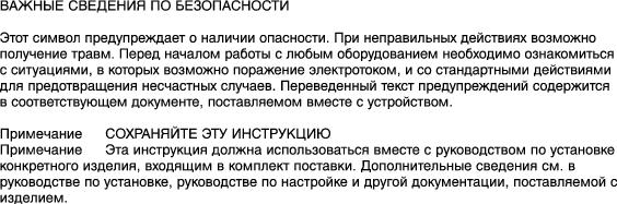
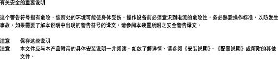
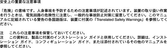
Safety Overview
Safety warnings appear throughout this publication in procedures that may harm you if performed incorrectly. A warning symbol precedes each warning statement.
Installing the OC-12 ATM Memory Kit
The section is divided into the following topics:
•
•

Warning
Required Tools
The following tools are required to perform the memory module installation procedure:
•
•
•
Removing the OC-12 ATM Module

Caution
Warning
To remove the OC-12 ATM module from the chassis, perform these steps:
Step 1
Step 2
Note
Step 3
Step 4
Horizontal slots
a.
b.
Vertical slots
a.
b.
Step 5
Figure 1 Opening the Ejector Levers (Horizontal Chassis Shown)
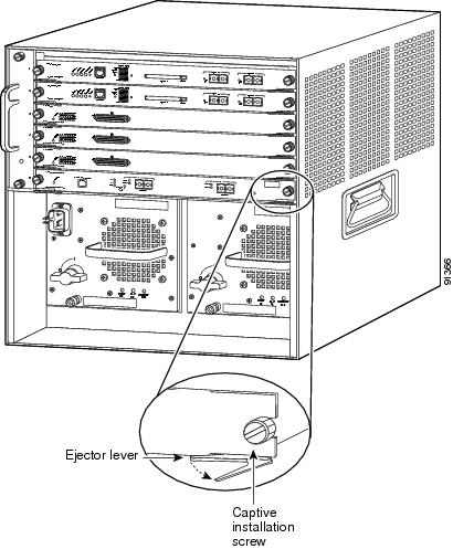
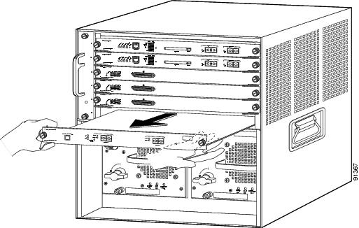
Figure 2 Removing the Module from the Chassis (Horizontal Chassis Shown)
Installing the DRAM DIMMs
The WS-OC12-32M-KIT= memory kit contains two 16-MB DRAM DIMMS that are installed in a DIMM socket located on the OC-12 ATM module. (See Figure 3.)
Caution
Note
Figure 3 OC-12 ATM Module DRAM DIMM Socket Location

To install the two DRAM DIMMs, perform the following steps:
Step 1
Step 2
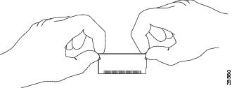
Figure 4 Handling a DIMM
Step 3
Caution
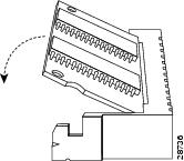
Figure 5 Installing the DIMM
Step 4
Step 5
Step 6
Installing the OC-12 ATM Module
Caution
To reinstall the OC-12 ATM module in the chassis, follow these steps:
Step 1
Note
Step 2
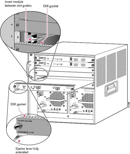
Figure 6 Positioning the Module in a Horizontal Slot Chassis
Step 3
Horizontal slots
a.
b.
c.
Note
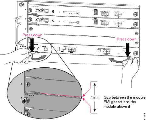
Figure 7 Clearing the EMI Gasket in a Horizontal Slot Chassis
d.
Note
e.
Note
f.
Vertical slots
a.
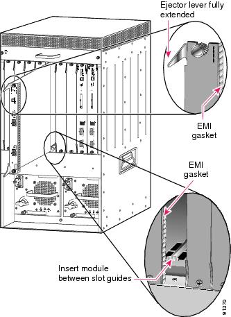
Figure 8 Positioning the Module in a Vertical Slot Chassis
b.
c.
Note
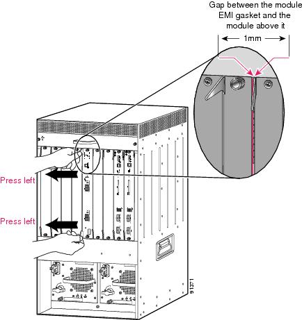
Figure 9 Clearing the EMI Gasket in a Vertical Slot Chassis
d.
e.
Note
f.
Translated Safety Warnings
This section repeats in multiple languages the basic warnings that appear in this publication.
Installation Warning
Lightning Activity Warning
Obtaining Documentation and Submitting a Service Request
For information on obtaining documentation, submitting a service request, and gathering additional information, see the monthly What's New in Cisco Product Documentation, which also lists all new and revised Cisco technical documentation, at:
http://www.cisco.com/en/US/docs/general/whatsnew/whatsnew.html
Subscribe to the What's New in Cisco Product Documentation as a Really Simple Syndication (RSS) feed and set content to be delivered directly to your desktop using a reader application. The RSS feeds are a free service and Cisco currently supports RSS Version 2.0.
This document is to be used in conjunction with the Catalyst 6500 Series Switch Module Installation Guide.
CCIP, CCSP, the Cisco Arrow logo, the Cisco Powered Network mark, the Cisco Systems Verified logo, Cisco Unity, Follow Me Browsing, FormShare, iQ Net Readiness Scorecard, Networking Academy, and ScriptShare are trademarks of Cisco Systems, Inc.; Changing the Way We Work, Live, Play, and Learn, The Fastest Way to Increase Your Internet Quotient, and iQuick Study are service marks of Cisco Systems, Inc.; and Aironet, ASIST, BPX, Catalyst, CCDA, CCDP, CCIE, CCNA, CCNP, Cisco, the Cisco Certified Internetwork Expert logo, Cisco IOS, the Cisco IOS logo, Cisco Press, Cisco Systems, Cisco Systems Capital, the Cisco Systems logo, Empowering the Internet Generation, Enterprise/Solver, EtherChannel, EtherSwitch, Fast Step, GigaStack, Internet Quotient, IOS, IP/TV, iQ Expertise, the iQ logo, LightStream, MGX, MICA, the Networkers logo, Network Registrar, Packet, PIX, Post-Routing, Pre-Routing, RateMUX, Registrar, SlideCast, SMARTnet, StrataView Plus, Stratm, SwitchProbe, TeleRouter, TransPath, and VCO are registered trademarks of Cisco Systems, Inc. and/or its affiliates in the U.S. and certain other countries.
All other trademarks mentioned in this document or Web site are the property of their respective owners. The use of the word partner does not imply a partnership relationship between Cisco and any other company. (0303R)
Copyright © 2003 Cisco Systems, Inc. All rights reserved.


 Feedback
Contact Cisco
- Open a Support Case

- (Requires a Cisco Service Contract)